ORDER NO.
PIONEER ELECTRONIC CORPORATION
4-1, Meguro 1-Chome, Meguro-ku, Tokyo 153-8654, Japan
PIONEER ELECTRONICS SERVICE, INC. P.O. Box 1760, Long Beach, CA 90801-1760, U.S.A.
PIONEER ELECTRONIC (EUROPE) N.V. Haven 1087, Keetberglaan 1, 9120 Melsele, Belgium
PIONEER ELECTRONICS ASIACENTRE PTE. LTD. 501 Orchard Road, #10-00 Wheelock Place, Singapore 238880
PIONEER ELECTRONIC CORPORATION 1998
c
RRV1986
MJ-L5
1. SAFETY INFORMATION ...................................... 2
2. EXPLODED VIEWS AND PARTS LIST ................ 3
3. SCHEMATIC DIAGRAM ..................................... 14
4. PCB CONNECTION DIAGRAM .......................... 32
5. PCB PARTS LIST ............................................... 44
6. ADJUSTMENT .................................................... 49
CONTENTS
7. GENERAL INFORMATION ................................ 59
7.1 IC ................................................................. 59
7.2 DIAGNOSIS ................................................. 75
7.3 DISASSEMBLY ........................................... 77
7.4 BLOCK DIAGRAM ....................................... 82
8. PANEL FACILITIES AND SPECIFICATIONS .... 84
T – IZY AUG. 1998 Printed in Japan
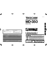
SP-L5
THIS MANUAL IS APPLICABLE TO THE FOLLOWING MODEL(S) AND TYPE(S).
SURROUND PROCESSOR
•
This products is a system component. It combined the following components.
MINIDISC RECORDER .................... MJ-L5
SURROUND PROCESSOR ............. SP-L5
•
This products is a system component.
For the system composition, refer to the service manual RRV1997 for XC-L5.
•
This product does not operate normally by itself. Please connect it to the STEREO CD RECEIVER XC-L5,
for adjustment and operation inspection. Otherwise damage may result.
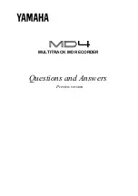
DELAY
TIME
SFC
MODE
MODE
SFC
ON/OFF
Ÿ
Ÿ
DOLBY SURROUND
P R O
• L O G I C
MINIDISC
ASES
7
0
6
¢
4
¡
•
+
–
•
1
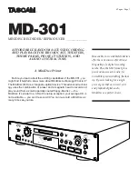
MINIDISC RECORDER
Type
Model
Power Requirement
Remarks
MJ-L5
SP-L5
MYXK
AC220-230V
NVXK
AC230V