ORDER NO.
PIONEER CORPORATION
4-1, Meguro 1-chome, Meguro-ku, Tokyo 153-8654, Japan
PIONEER ELECTRONICS (USA) INC.
P.O. Box 1760, Long Beach, CA 90801-1760, U.S.A.
PIONEER EUROPE NV
Haven 1087, Keetberglaan 1, 9120 Melsele, Belgium
PIONEER ELECTRONICS ASIACENTRE PTE. LTD.
253 Alexandra Road, #04-01, Singapore 159936
PIONEER CORPORATION 2006
DVZ-MG6067ZH/UC
CRT3654
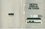
6 DVD TUNER
DVZ-MG6067
ZH
/UC
DVZ-MG6167
ZH
/CA
This service manual should be used together with the following manual(s):
VEHICLE
DESTINATION
PRODUCED
AFTER
OEM PARTS No.
ID No.
PIONEER MODEL No.
U.S.A., CANADA
August 2006
39101-STK-A110-M1
-
DVZ-MG6067ZH/UC
CANADA
August 2006
39101-STK-C110-M1
-
DVZ-MG6167ZH/CA
Model No.
Order No.
Mech.Module
Remarks
CX-3150
CRT3495
MG4
DVD Mech. Module:Circuit Descriptions, Mech. Over View, Disassembly, How
to Assemble
For details, refer to "Important Check Points for Good Servicing".
K-ZZA. MAY 2006 Printed in Japan
HONDA
Summary of Contents for DVZ-MG6067ZN/UC
Page 8: ...DVZ MG6067ZH UC 8 1 2 3 4 1 2 3 4 C D F A B E 2 2 DVD MECHANISM MODULE ...
Page 25: ...DVZ MG6067ZH UC 25 5 6 7 8 5 6 7 8 C D F A B E B a B b B b 4 5 A CN106 ...
Page 27: ...DVZ MG6067ZH UC 27 5 6 7 8 5 6 7 8 C D F A B E A a B b B a B a B b 4 5 CN1901 2 2 D ...
Page 29: ...DVZ MG6067ZH UC 29 5 6 7 8 5 6 7 8 C D F A B E C C KEYBOARD UNIT ...
Page 35: ...DVZ MG6067ZH UC 35 5 6 7 8 5 6 7 8 C D F A B E A a D b D a D b 1 2 D a 1 2 F PD6540A NM ...
Page 37: ...DVZ MG6067ZH UC 37 5 6 7 8 5 6 7 8 C D F A B E 2 2 D DVD CORE UNIT 2 2 2 2 D 0R0 B CN1601 ...
Page 42: ...DVZ MG6067ZH UC 42 1 2 3 4 1 2 3 4 C D F A B E A A TUNER CONTROL UNIT PCL2 TESTIN ...
Page 43: ...DVZ MG6067ZH UC 43 5 6 7 8 5 6 7 8 C D F A B E A SIDE B ...
Page 47: ...DVZ MG6067ZH UC 47 5 6 7 8 5 6 7 8 C D F A B E D SIDE A 60 70 80 90 100 110 120 ...
Page 48: ...DVZ MG6067ZH UC 48 1 2 3 4 1 2 3 4 C D F A B E D D 6 70 80 90 100 110 120 DVD CORE UNIT ...
Page 93: ...DVZ MG6067ZH UC 93 5 6 7 8 5 6 7 8 C D F A B E ...