ORDER NO.
PIONEER CORPORATION
4-1, Meguro 1-chome, Meguro-ku, Tokyo 153-8654, Japan
PIONEER ELECTRONICS (USA) INC.
P.O. Box 1760, Long Beach, CA 90801-1760, U.S.A.
PIONEER EUROPE NV
Haven 1087, Keetberglaan 1, 9120 Melsele, Belgium
PIONEER ELECTRONICS ASIACENTRE PTE. LTD.
253 Alexandra Road, #04-01, Singapore 159936
PIONEER CORPORATION 2004
DV-PT100-S
REC
DV-PT100-S
RRV3041
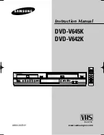
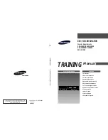
DVD PLAYER & VCR
DV-PT100-S
THIS MANUAL IS APPLICABLE TO THE FOLLOWING MODEL(S) AND TYPE(S).
Model
Type
Power Requirement
Region No.
Remarks
DV-PT100-S
KUXTL
AC120V
1
For details, refer to "
Important Check Points for Good Servicing
" .
T-ZZR OCT. 2004 printed in Japan