Note:
• This unit is for vehicles with a 12-volt battery and
negative grounding. Before installing it in a recre-
ational vehicle, truck, or bus, check the battery
voltage.
• To avoid shorts in the electrical system, be sure to
disconnect the
≠
battery cable before beginning
installation.
• Refer to the owner’s manual for details on con-
necting the power amp and other units, then make
connections correctly.
• Secure the wiring with cable clamps or adhesive
tape. To protect the wiring, wrap adhesive tape
around them where they lie against metal parts.
• Route and secure all wiring so it cannot touch any
moving parts, such as the gear shift, handbrake
and seat rails. Do not route wiring in places that
get hot, such as near the heater outlet. If the insula-
tion of the wiring melts or gets torn, there is a dan-
ger of the wiring short-circuiting to the vehicle
body.
• Don’t pass the yellow lead through a hole into the
engine compartment to connect to the battery. This
will damage the lead insulation and cause a very
dangerous short.
• Do not shorten any leads. If you do, the protection
circuit may fail to work when it should.
• Never feed power to other equipment by cutting
the insulation of the power supply lead of the unit
and tapping into the lead. The current capacity of
the lead will be exceeded, causing overheating.
• When replacing fuse, be sure to use only fuse of
the rating prescribed on the fuse holder.
• Since a unique BPTL circuit is employed, never
wire so the speaker leads are directly grounded or
the left and right
≠
speaker leads are common.
• If the RCA pin jack on the unit will not be used, do
not remove the caps attached to the end of the con-
nector.
• Speakers connected to this unit must be high-
power types with minimum rating of 50 W and
impedance of 4 to 8 ohms. Connecting speakers
with output and/or impedance values other than
those noted here may result in the speakers catch-
ing fire, emitting smoke, or becoming damaged.
• When this product’s source is switched ON, a con-
trol signal is output through the blue/white lead.
Connect to an external power amp’s system remote
control or the car’s Auto-antenna relay control ter-
minal (max. 300 mA 12 V DC). If the car features
a glass antenna, connect to the antenna booster
power supply terminal.
• When an external power amp is being used with
this system, be sure not to connect the blue/white
lead to the amp’s power terminal. Likewise, do not
connect the blue/white lead to the power terminal
of the auto-antenna. Such connection could cause
excessive current drain and malfunction.
• To avoid short-circuiting, cover the disconnected
lead with insulating tape. Especially, insulate the
unused speaker leads without fail. There is a possi-
bility of short-circuiting if the leads are not insulat-
ed.
• To prevent incorrect connection, the input side of
the IP-BUS connector is blue, and the output side
is black. Connect the connectors of the same colors
correctly.
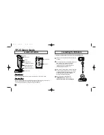
• If this unit is installed in a vehicle that does not
have an ACC (accessory) position on the ignition
switch, the red lead of the unit should be connected
to a terminal coupled with ignition switch ON/OFF
operations. If this is not done, the vehicle battery
may be drained when you are away from the vehi-
cle for several hours. (Fig. 1)
Fig. 1
• The black lead is ground. Please ground this lead
separately from the ground of high-current prod-
ucts such as power amps.
If you ground the products together and the ground
becomes detached, there is a risk of damage to the
products or fire.
• Cords for this product and those for other products
may be different colors even if they have the same
function. When connecting this product to another
product, refer to the supplied manuals of both
products and connect cords that have the same
function.
No ACC position
ACC position
ON
S
T
A
R
T
O
FF
ACC
ON
S
T
A
R
T
O
FF
INST
ALLA
TION MANUAL
MANUEL D’INST
ALLA
TION
<KMMZX> <03L00000>
ENG/MASTER COVER 98 INST
DEH-P860MP
Printed in Thailand
Imprimé en Thaïlande
<CRD3829-A/N> UC
This product conforms to CEMA cord colors.
Le code de couleur des câbles utilisé pour ce produit est con-
forme à CEMA.
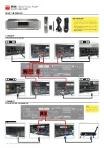
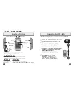
Connecting the Units
<ENGLISH>
Fig. 2
Connection diagram for standard mode
+
≠
+
≠
+
≠
+
≠
+
≠
+
≠
+
≠
+
≠
+
≠
+
≠
Left
Right
Fuse resistor
Fuse resistor
Fuse holder
Perform these connections when using
the optional amplifier.
With a 2 speaker system, do not
connect anything to the speaker leads
that are not connected to speakers.
Yellow/black
If you use a cellular telephone, connect
it via the Audio Mute lead on the
cellular telephone. If not, keep the
Audio Mute lead free of any
connections.
Yellow
To terminal always supplied with
power regardless of ignition switch
position.
Red
To electric terminal controlled by
ignition switch (12 V DC) ON/OFF.
Orange/white
To lighting switch terminal.
Black (ground)
To vehicle (metal) body.
Gray
Gray/black
Violet
Violet/black
White
White/black
Green
Green/black
Connecting cords with RCA pin
plugs (sold separately)
Power amp
(sold separately)
System remote control
Power amp
(sold separately)
Power amp
(sold separately)
Blue/white
To system control terminal of the power amp or
Auto-antenna relay control terminal (max. 300
mA 12 V DC).
Subwoofer output
(LOW/SUBWOOFER OUTPUT)
Rear output
(MID/REAR OUTPUT)
Front output
(HIGH/FRONT OUTPUT)
Rear speaker
Front speaker
Subwoofer
Front speaker
Front speaker
Front speaker
Rear speaker
Rear speaker
Rear speaker
Subwoofer
This terminal may or may
not be included.
23 cm (9 in.)
15 cm (5-7/8 in.)
DSP switch
Switch the DSP switch
as illustration below.
Antenna jack
15 cm (5-7/8 in.)
IP-BUS input
(Blue)
Multi-CD player
(sold separately)
IP-BUS cable
This product
Jack for the Wired Remote Control
Refer to Wired Remote Control’s manual
(sold separately).
CRD3829AN 03.12.8 7:51 PM Page 1