background image


Chapter 7 


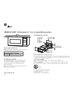
Summary of Contents for TW0200

Page 1: ...Chapter 7 ...

Page 2: ...153 ...

Page 3: ...154 ...

Page 4: ...155 ...

Page 5: ......

Page 6: ...157 ...

Page 7: ...158 ...

Page 8: ...Meters HP Scalar network analyzer 8757 A HP Sweep Generator 8350 B Wiltron scalar network analyzer 56100 A Wiltron Synthesized sweep generator 68147 B Radart 2424 Synthesized signal generator 10 KHz 10 4 GHz Adaptor S N 9610 63090 MFR 63661 Anritsu open short model 22 N 50 8 Power sensors Low power 70 to 20 dBm High power 20 to 20 dBm 9 Attenuators 10 20 dB HP or Anritsu 10 Jitter modulator oscill...

Page 9: ...th is 0 5 ohms 4 Before starting local A T carry out a physical inspection of installation Tower W G Earthing and its entrance in equipment room 5 Confirm that all required meters RF cords available or not This is important because so many types of meters and cords are required in M W A T 6 Check whether W G entry is through hatch plate or not 7 Obtain equipment room layout of all stations along w...

Page 10: ...161 ...

Page 11: ...162 ...

Page 12: ...163 ...

Page 13: ...164 ...

Page 14: ...165 ...

Page 15: ...166 ...

Page 16: ...167 ...

Page 17: ...168 ...

Page 18: ...169 ...

Page 19: ...170 ...

Page 20: ...171 ...

Page 21: ...172 ...

Page 22: ...e Check the gauges of wires and loose connections Output voltages some systems are not having access points to measure the output voltages a Modem shelf PSU 5 2 V 3 3 V and 5 2V Limit 0 25V 0 15V and 0 25V b RSA shelf PSU 5 3V 12 0V 5 5V Limit 0 25V 0 5V 0 25V 2 Test on Transmitter TLO Write down the assigned frequency of TLO and measure by Microwave frequency counter at TLO Mon Press impedance 50...

Page 23: ...174 ...

Page 24: ... 20 dB attenuator for 20 dBm level Adjust 3 dBm by IF level potentiometer and then vary AGC input level by microwave Variable attenuator Start by 20 dBm as 17 is overload and note down the BITE reading and DC Mon voltage Go low by 10 dB step up to 70 dBm and after that lower the level by 1 dBm until a receive alarm is monitored The level at which Rx fail LED glows is a threshold level for BER of 1...

Page 25: ...due to phase difference voltage tends to minimum also Cause of worst VSWR Inside damage of waveguide bends inside water loose connections inside holes etc If not within limit then required receive level is not possible at distant end degradation of services poor coverage in case of GSM Return Loss It is a ratio of amplitude of reflected wave to the amplitude of incident wave This loss shows reduct...

Page 26: ...177 ...

Page 27: ...1 10 26 4 4 8 0 828 1 11 25 7 5 2 0 906 1 12 24 9 5 7 0 984 1 13 24 3 6 1 1 06 1 14 23 7 6 5 1 04 1 15 23 1 7 0 1 14 1 18 21 7 8 3 1 21 1 20 20 8 9 1 1 44 1 30 17 7 13 0 1 58 1 50 14 0 19 95 2 28 1 43 15 0 17 78 1 38 16 0 15 85 1 33 17 0 14 13 1 29 18 0 12 59 1 25 19 0 11 12 1 222 20 0 10 00 1 196 21 0 8 93 1 173 22 0 7 943 1 152 23 0 7 079 1 135 24 0 6 310 1 119 25 0 5 563 1 106 26 0 5 012 1 094 ...

Page 28: ...179 ...

Page 29: ...180 ...

Page 30: ...e Analyzer Start calibration Select Open Short Calibration completed Connect device Move cursor on get trace for max and minimum Open short Analyzer with sensor Generator blue cord Compiler Fig 7 13 Select 11 GHz band take marker on max and min by function switch and select max 26 34 dBm 7 2 3 Some General test Image Frequency Rejection test Image Frequency Receive frequency 2 IF Feed Image freque...

Page 31: ...alyzer Limit Better than 70 dB Rx Tx Feed Rx RF at antenna port and measure at co axial cable connected to PA out Limit Better than 70 dB 7 Waveguide pressurization in Kg Cm2 Note down Waveguide pressure in Kg Cm2 8 Some test of 7 GHz system ALC Test Automatic level control Make the test set up as below Fig 7 14 feed 3 dBm to IF in Adjust 30 dBm at PA out Vary IF level from 1 to 7 dBm Observe leve...

Page 32: ...t Limit is 5 1 dBm asu e AGC voltage at connector M 69 pin 1 8 reading may be 6 0 V re ce only It is the transit time delay effect The transit time for a transmission path is a or current to travel through the transmission path This e required by a specific voltage time is given by the rate of phase shift a Ta t ke est in MGC Manual Gain control only keep al MLA Transmitter at one end MLA receive ...

Page 33: ...cked as per sheet monitoring Trans Receive power are to be monitored with PC g test Arrange 2 Mb loops from distant station and check J tter measurement as mentioned in OFC systems Pl y out I P Jitter test for both Main and Protecti uencies 200 Hz 500 Hz 10 KHz 3500 KHz and note down the results in UIPP O P Jitter Select F r Limits pl see the table 6 AIS measurement Measure AIS frequency by freque...

Page 34: ... is increased gain increased Size of antenna depends upon operating frequency Atmospheric losses and Rain losses 2 0 2 3 GHz 0 6 M dia 19 6 dB 1 2 M dia 25 6 dB 1 1 8 M dia 45 1 dB me er 2 G 6G 7 G 11 G 1 8 M 29 38 3 39 2 43 8 dB 43 0 45 0 48 1 dB It is to be done to avoid moisture dirt and corrosive gasses W G are etime high o required for sealing against leaks One of such dehydrator is from High...

Page 35: ... gain in both directio L Free space loss FL Feeder cable loss in both directions Br Branching filter loss at both end This Receive power to be calculated for RF IN or Rx IN and Branching filter loss 5 60 dB Feeder loss 7 52 dB 4 70 dB 100 Total loss 157 72 dB Antenna gain 45 60 X 2 Trans power Total gain 121 20 dB 4 Wave guide It is a hallow copper corrugated w energy at higher frequencies It is g...

Page 36: ...s are decoupled by XPD of antenna at the receiving end c The first zone is circular sub second zones are annul with first This zone concept is used to analyze interference by obstacle Second by r T A R Hilly Terrain 6 Fading It is a distortion in micro media and introduces errors There are two types of fading 1 Slow shadow fading It is on large scale due to movements of mobile or obstruction withi...

Page 37: ...operating frequency within 10 15 GHz This rain attenuation can be reduced by interconnecting two stations separated by di greater than 9 Diversity If channel is affected by loading then second channel will take load here configuration Parallel system is provided so that two systems can carry the same equipment frequency diversity As it is required two sets of equipment frequenci equipment is more ...

Page 38: ... with different propagation path with the help of second antenna at receiving end to improve received performance 7 3 5 10 Hot stand by If main equipment fails automatic switch over takes place on a stand by equipment set i e a complete set of parallel equipment is switched in almo operating equipment This is also called a equipment diversity It requires only one set of frequency for frequency for...

Page 39: ...C OFF strap between 10 to 8 16 i urve rate For this test Fade simulator is required 8 14 IF DADE Di main and space diversity antenna This phase difference causes loss of bits DADE cable is used and it is placed between IF out and RX2 IN It contains a delay cable of length L to compensate the delay time difference between main and Receiver and space diversity receiver is available in order to reduc...

Page 40: ...th resist e test of Equipment tower and if it is not checked within 6 months ARM Sub Rack New 7 19 20 Diplexer Bit Rate 8 448 MHz 75 Ω Tx Rx Spacing 161 MHz RF Tx 30 to 32 dBm at antenna port Receive IF frequency 70 MHz Transmitter PA out 34 dBm max AGC dynamic Receive Threshold for BER of 1 x 10 3 86 d Noise level 53 dBm 4 2 Before starting Local A T Ensure availability of M W testing meters Ask ...

Page 41: ...192 ...

Page 42: ... test for protection channel 4 Check of alarms Verify the following alarm by simulating the conditions a Rx select b Tx select c Tx power low d E 6 AGC voltage e E 3 Ground f Data unlock g RLO unlock h Data fail i RF fail j Synch fail k BER LED O K l Alarm in BITE O K m AIS 5 Bay Meter readings AGC voltage for both channels P S checks 48 and 12 8 V BER E 3 and E 6 6 Check of Mux Equipment There ar...

Page 43: ...d PS2 12 8 Equipment status O K 25 GHz Tx power A 33 dBm B 33 dBm 5 dBm A Rx frequency 2 2235 GHz Ref DOT ML sector 7 GHz 34 Mb 2 BER test Ask distant station to loop all four tributaries and check BER on all four Trbs for 0 and 50 PPM for Limit 0 00 E 10 No Error 3 Check of switching operatio Take loop on one tributary fro Connect DTA to 1st tributary and monitor loop getting O K Now put OFF main...

Page 44: ...nitor following vari Data fail T R unit when I P HDB3 data failure RF fails in BITE When power 30 dBm TLO unlock when synthesizer goes out Receiver RLO unlock in BITE Synch fail in BITE when synch is not r BER LED in BITE BER worst than E 3 8 Check all Tower A T points as per test schedule along with Earth measurement 9 Stability Put ON stability for 24 Hours by Limit ES 0 18 SES 0 003 revised 0 0...

Reviews: