background image


Service Manual

Service

Service

Service

Service

Service

SW3000/

00S/06S

©

 Copyright 2002 Philips Consumer Electronics B.V. Eindhoven, The Netherlands

All rights reserved.  No part of this publication may be reproduced, stored in a retrieval system or
transmitted, in any form or by any means, electronic, mechanical, photocopying, or otherwise
without the prior permission of Philips.

Published by KC-ET0212 Service Audio Printed in The Netherlands

Subject to modification

Active  Subwoofer

Version 1.0

TABLE OF CONTENTS

Page

Location of PC Boards/Specifications ........................ 1-2

Specifications .............................................................. 1-2

Measurement Setup ................................................... 1-3

ESD & Safety Instruction ............................................ 1-4

Disassembly Instructions & Service Positions .............. 2

Set Block & Wiring Diagram .......................................... 3

Power Board .................................................................. 4

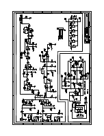
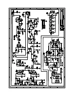
Combi Board .................................................................. 5

Mechanical Exploded View & Parts List ........................ 6

SW3500/

02S/06S/17S

GB

3139 785 30057

Summary of Contents for SW3000/00S

Page 1: ...hanical photocopying or otherwise without the prior permission of Philips Published by KC ET0212 Service Audio Printed in The Netherlands Subject to modification Active Subwoofer Version 1 0 TABLE OF CONTENTS Page Location of PC Boards Specifications 1 2 Specifications 1 2 Measurement Setup 1 3 ESD Safety Instruction 1 4 Disassembly Instructions Service Positions 2 Set Block Wiring Diagram 3 Power...

Page 2: ... at 80 Hz output power Reproduction Frequency Response 30 Hz 180 Hz Phase Switch 00 1800 Input Sensitivity Subwoofer In 200 mVrms AC Power for SW3500 37S 120V 60 Hz AC Power for SW3000 06S SW3500 06S 110 127V 60 Hz AC Power for SW3000 00S 220 240V 50Hz AC Power for SW3000 00S SW3500 02S 220 240V 50 60 Hz power Consumption 53 W at 1 8 Rated Power Dimensions w x h x d 130 mm x 337 mm x 375 mm Weight...

Page 3: ...1 3 MEASUREMENT SETUP ...

Page 4: ... Houd componenten en hulpmiddelen ook op ditzelfde potentiaal I AVVERTIMENTO Tutti IC e parecchi semi conduttori sono sensibili alle scariche statiche ESD La loro longevità potrebbe essere fortemente ridatta in caso di non osservazione della più grande cauzione alla loro manipolazione Durante le riparazioni occorre quindi essere collegato allo stesso potenziale che quello della massa dell apparecc...

Page 5: ...lace the Subwoofer Box as shown in the Picture 3 Bottom view and use a screw driver to force open the front assembly Dismantling the Rear assembly 1 Loosen 9 screws B as shown in the Picture 4 Rear View to pull out the Printed Circuit Board assembly Caution Do not break the bundle of wires to the front Take care the surface when take out the front panel of subwoofer Caution Do not break the bundle...

Page 6: ...2 2 SERVICE POSITION ...

Page 7: ...3 1 3 1 SET BLOCK DIAGRAM INPUT BOARD LED BOARD AMPLIFIER BOARD POWER BOARD ...

Page 8: ...3 2 3 2 SET WIRING DIRGRAM 51 53 54 52 50 POWER PCB LED PCB AMPLIFIER PCB INPUT PCB LVM0180C021 LVM0180C011 LVM0180C031 fixed detachable either or ...

Page 9: ...l Parts List 4 3 4 1 4 1 PCB LAYOUT VIEW POWER BOARD C358 F3 C359 F3 C361 E1 C362 E2 C363 E2 C364 F2 C901 C3 CN901 B2 CN902 B3 D353 E3 D354 D1 D355 D1 D356 D3 F901 C2 Q354 E4 Q355 E4 Q357 E2 Q377 E3 R378 E3 R379 E3 R380 E4 R381 E4 R382 E2 R383 E2 RB351 F3 RL901 C4 T901 C4 ZD350 F2 ...

Page 10: ...B1 C361 B2 C362 B2 C363 B2 C364 B1 C901 C4 CN901 C5 CN902 B5 D353 C3 D354 A3 D355 B3 D356 C3 F901 C4 Q354 C2 Q355 C3 Q357 B2 R377 C2 R378 C3 R379 B3 R380 C3 R381 C3 R382 B2 R383 B2 RB351 C1 RB901 C5 RB902 B5 RB906 A6 RL901 C4 T901 B6 T902 B4 ZD350 B2 ...

Page 11: ...640 470UF 35V 20 C362 2038 554 00065 100NF 80 20 50V C363 9965 000 12559 100UF 16V 20 C364 2038 554 00065 100NF 80 20 50V C901 9965 000 12604 0 01UF 20 RESISTORS R377 4822 050 22203 22K 1 0 6W R378 9965 000 12641 62K 1 6W 5 R379 4822 116 83868 150R 5 0 5W R380 9965 000 12629 30K 1 6W 5 R381 4822 050 24703 47K 1 0 6W R382 4822 116 52218 300R 5 0 5W R383 4822 116 52263 2 7K 5 0 5W DIODES D353 4822 1...

Page 12: ...COMBI BOARD TABLE OF CONTENTS Internal IC Diagram 5 1 Circuit Diagram 5 2 PCB Layout View 5 3 Electrical Parts List 5 4 5 1 5 1 INTERNAL IC DIAGRAM ...

Page 13: ...5 2 5 2 CIRCUIT DIAGRAM COMBI BOARD AMPLIFIER SCHEMATIC INPUT SCHEMATIC LED SCHEMATIC ...

Page 14: ...5 3 5 3 PCB LAYOUT VIEW COMBI BOARD ...

Page 15: ... 2K 1 0 6W R340 9965 000 12620 1 8K 1 6W 5 R350 4822 050 24703 47K 1 0 6W R351 4822 050 21004 100K 1 0 6W R352 4822 050 21004 100K 1 0 6W R353 9965 000 09725 4 7K 1 6W 5 CF R354 9965 000 12621 2K 1 6W 5 R355 9965 000 12622 2 2M 1 6W 5 R356 4822 050 21003 10K 1 0 6W R357 9965 000 12623 82R 1 6W 5 R358 9965 000 12624 270K 1 6W 5 R359 9965 000 12624 270K 1 6W 5 R360 4822 050 21003 10K 1 0 6W R361 482...

Page 16: ...6 1 6 1 MECHANICAL EXPLODED VIEW use for SW3000 00S SW3500 02S use for SW3000 00S 06S SW3500 06S 17S LINE CORD TYPE A2 A1 ...

Page 17: ...H FRAME ASSY SW3500 ORANGE 4 9965 000 12978 LED PCB ASSEMBLY 8 9965 000 12979 MAINS TRANSFORMER 120V 06S 17S 8 9965 000 12982 MAINS TRANSFORMER 230V 00S 02S 29 9965 000 12818 MAINS CORD 17S FIXED 29 9965 000 12819 MAINS CORD 06S FIXED 29 9965 000 12820 MAINS CORD 00S 02S DETACHABLE 29 9965 000 12821 MAINS CORD 00S AUSTRALIA FIXED 30 9965 000 07092 BUSHING FIXED CORD 30 9965 000 12443 AC SOCKET DET...

Reviews: