Philips Signage Solutions BDL4678XL, User Manual
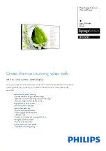
The Philips Signage Solutions BDL4678XL is a leading-edge display offering exceptional clarity and vibrant visuals. Access its detailed Specifications and user manual for free download at manualshive.com, enabling you to maximize the potential of this innovative product in your business or personal space.
Share
Download


Reviews:
No comments