background image

DVD Portable Player 


   PET1046 


All version 


      3141 785 33270 


Version 

1.0 


©

Copyright 2005 Philips Consumer Electronics B.V. Eindhoven, The Netherlands 

All rights reserved. No part of this publication may by reproduced, stored in a 
retrieval system or transmitted, in any form or by any means, electronics, 
mechanical, photocopying, or otherwise without the prior permission of Philips 
 
Published by FK 0851 AVM 

Printed in the Netherlands 

Subject to Modification 

TABLE OF CONTENTS 


Chapter 


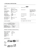
Technical Specification & Service Tips…………..………..  1 
Safety Instructions……………………………………………..  2 
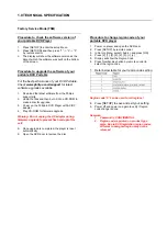
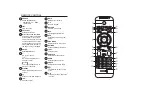
Instruction for Use……………………………………………… 3 
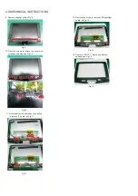
Mechanical Instructions………………………………………. 4 
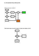
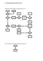
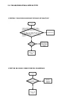
Troubleshooting …………………………………………………5 
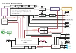
Overall Block Diagram…………………………………………. 6 
Overall Wiring Diagram…………………………………………7 
Electrical Diagram……………………………………………… 8 
Component Layout…………………………………………….  9 
Service Part List………………………………………………… 10 
Revision List…………………………………………………….  11 


Service Manual 


Summary of Contents for PET1046

Page 1: ... any means electronics mechanical photocopying or otherwise without the prior permission of Philips Published by FK 0851 AVM Printed in the Netherlands Subject to Modification TABLE OF CONTENTS Chapter Technical Specification Service Tips 1 Safety Instructions 2 Instruction for Use 3 Mechanical Instructions 4 Troubleshooting 5 Overall Block Diagram 6 Overall Wiring Diagram 7 Electrical Diagram 8 C...

Page 2: ...umption DC IN SUPPLY 9V Battery Charging Current 2 2A typical BATT SUPPLY 7 2V Power Off 0A Playback with TFT on 2 2A typical Playback without TFT on 600mA Battery time playback 2 5 hour Headphone out headphone output load 2x16 ohm Maximum output power 10mW Frequency response 20Hz 20kHz SNR A wght 80dB typical THD 0 2 20kHz 1 Left Right Channel Separation 32dB Left Right Channel Balance 1dB Suppor...

Page 3: ...lay CD ROM for firmware upgrade Warning Do not unplug the AC adaptor during firmware upgrade to prevent flash corrupt of the set 5 Once upgrade is completed the player is reset automatically 6 Open the DVD door to remove the disc Procedure to change region code of your portable DVD player 1 Power on player and open the DVD door 2 Press SETUP by remote control 3 In Set Up Menu select Audio and pres...

Page 4: ... caso di non osservazione della più grande cauzione alla loro manipolazione Durante le riparazioni occorre quindi essere collegato allo stesso potenziale che quello della massa dell apparecchio tramite un braccialetto a resistenza Assicurarsi che i componenti e anche gli utensili con quali si lavora siano anche a questo potenziale Pour votre sécurité ces documents doivent être utilisés par des spé...

Page 5: ... operates properly after replacement if it was subject to electrostatic discharge during replacement its life might be shortened When replacing use a conductive mat soldering iron with ground wire etc to protect the laser diode form damage by static electricity And also the LSI and IC are same as above Soldering iron with ground wire or ceramic type Ground conductive wrist strap for body Conductiv...

Page 6: ...xists the fault must be located and corrected Repeat the above test with the DVD VIDEO PLAYER power plug reversed NEVER RETURN A DVD VIDEO PLAYER TO THE CUSTOMER WITHOUT TAKING NECESSARY CORRECTIVE ACTION READING SHOULD NOT EXCEED 0 3V DVD VIDEO PLAYER AC OUTLET AC VOLTMETER Test all exposed metal Voltmeter Hook up for Leakage Current Check 0 15uF 150V AC 1500 10W 5000 per volt or more sensitivity...

Page 7: ...VOL OPTION DISC MENU Access additional functions SETUP Enter SETUP menu Volume control Volume control previous next track or fast search backward forward Display MUNE page Up down left right cursor 4 Start pause resume playback POWER Switches the player on off 15 OK Confirm seletion DC IN 9V Power supply socket RESET Reset the player when it is hanged up 23 ANTENNA Connection to antenna plug 24 25...

Page 8: ...ed keys are used to access the items or corres ponding pages The coloured areas flash when the item or the page is not yet available Adjust the display value of the system 8 Press once to stop playback View channels Up down navigation key Channel control SOURCE LIST Switch between DVD Component TV Radio USB AV in 18 TELETEXT Activate TELETEXT Volume control SUBTITLE Subtitle language selector AUDI...

Page 9: ...short pattern for laser diode as Fig 6 3 Fig 2 Remove screws of the base cover as Fig 3 Fig 3 Fig 4 4 Open the door and remove screws to remove door middle cabinet discreteness as Fig 4 5 Rotate the top and remove screws to break the top and the base away as Fig 5 Fig 5 7 Fig 6 Remove screws to remove lithium battery as Fig 7 8 Remove screws to remove mian board and powerkey board as Fig 8 Fig 7 F...

Page 10: ...e screws to remove top cover disc reteness and hinge as Fig 10 Fig 10 11 Remove screws and broken connection to remove IF board as Fig 11 12 Fig 11 Remove the screw to remove LED backlight board as Fig 12 13 Remove LCD TFT function board and speakers as Fig 13 Fig 12 Fig 13 ...

Page 11: ...n set to customer yes start set OK Check if the power and play button OK replace connector and switch unit replace MAIN BOARD go to other SYMPTOM no yes yes no replace DVD drive SYMPTOM NO IMAGE OR SOUND COMES OUT FROM THE EXTERNAL OUTPUT start Check operation of the DVD drive Does the DVD drive work yes no Replace the main board or the connector ...

Page 12: ...nnector harness broken Replace broken harness yes Remove the LCD cover and plate of the LCD unit to check the connector of the FL harness Is the connector OK no Repair connector Replace FL inverter or LCD no yes Is the connector broken Replace LCD harness or main board yes Remove the LCD cover and plate of the LCD unit to check the connection of the harness to the LCD unit no Is the connection OK ...

Page 13: ...re the connection of the DVD drive and main board Not OK Pick up lens light up OK Insert a DVD disc and turn on the power What is the reaction of the DVD drive The DVD drive works but the initializing operation of the optical pick up lens does not start the optical pick up lens operates twice or abnormal noise sound Replace DVD drive or main board DVD drive does not work The operation of the DVD p...

Page 14: ...tall a good battery does the LED lights up orange while the AC adapter is connected and does the DVD drive operate OK NOTE For this check use a battery which is not fully charged because the LED does not light when the battery is fully charged Before this check make sure other function work correctly no SYMPTOM NO SOUND COMES FROM THE HEADPHONES start Replace main board yes Insert a good headphone...

Page 15: ...R BA5888 16M FlashROM KH29LV160CBTC 70G 128M SDRAM HY57V281620ETP H C TC4W53 27MHz TFT MONITOR AUDIO AMP AZ4558 DC DC AT1308 DC DC AT1313 LED BACKLIGHT ASS Y 74HCU04 L R DRIVER 5V 5V 5V 3 3V 1 8V TFT POWER TPA6011 SD MMC MS CARD COMP OUT S VIDEO AUDIO OUT PHONE OUT SPEAKER LOUT SPEAKER ROUT USB ANTENNA COAXIAL OUT AUDIO IN 5V 15V 10V 8V VIDEO OUT VIDEO IN AUDIO 5V 5V T103 MT8606 TUNER 27MHz 27MHz ...

Page 16: ...GND HSY VSY GND BIN GND GIN GND RIN GND AVIN GND GND RESET IISCL IISDA 1 2 3 4 5 6 7 8 9 10 11 12 13 14 15 16 17 18 19 20 21 22 23 24 30 29 28 27 26 25 24 23 22 21 20 19 18 17 16 15 14 13 12 11 10 9 8 7 6 5 4 3 2 1 30 29 28 27 26 25 24 23 22 21 20 19 18 17 16 15 14 13 12 11 10 9 8 7 6 5 4 3 2 1 GND R0 R1 R2 R3 R4 R5 GND V2 V4 V6 V8 V10 AVDD 8V8 GND VCOM GND V13 VGH V14 VGL V12 3V3P GND GND STV1 DI...

Page 17: ...24 TP24 L02 601 L02 601 R42 1K R42 1K TP20 TP20 1 1 2 2 3 3 4 4 5 5 6 6 7 7 8 8 16 16 15 15 13 13 14 14 12 12 11 11 10 10 9 9 D7 MC9S08QG4 D7 MC9S08QG4 R164 680k R164 680k TP21 TP21 CB116 0 1uF CB116 0 1uF TP7 TP7 C125 10uF 16V C125 10uF 16V TP10 TP10 TP13 TP13 L3 601 L3 601 COMMON 1 INH 2 VEE 3 VSS 4 VDD 8 CH0 7 CH1 6 A 5 D1 TC4W53 D1 TC4W53 R100 0 R100 0 TP50 TP50 CB48 0 1uF CB48 0 1uF 1 2 C24 1...

Page 18: ...9 TPA6011 R65 10K R65 10K R116 10K R116 10K VD525 1SS355 VD525 1SS355 VD407 KTA1298 VD407 KTA1298 C12 220U 6 3V C12 220U 6 3V R201 10K R201 10K R208 100K R208 100K C17 10u 10v C17 10u 10v EM1 10M EM1 10M OUT1 1 IN1 2 IN1 3 VEE 4 IN2 5 IN2 6 OUT2 7 VCC 8 N501 BA4558 N501 BA4558 L55 601 L55 601 R45 33 R45 33 VD521 1SS355 VD521 1SS355 C32 10u 10v C32 10u 10v R560 470 R560 470 R519 6 8K R519 6 8K L54 ...

Page 19: ... 15K R159 15K R159 15K CB115 0 1uF CB115 0 1uF R161 10K R161 10K R21 0 R21 0 R90 10k R90 10k R11 10K R11 10K R153 33 R153 33 CB96 NC CB96 NC CB146 0 1uF CB146 0 1uF R3 33 R3 33 R156 33 R156 33 R20 10K R20 10K 2 1 3 VD23 AO3401 VD23 AO3401 R197 10K R197 10K 2 1 3 VD1 2SD601 VD1 2SD601 R4 0 R4 0 C115 10uF 10V C115 10uF 10V R77 15K R77 15K VCC 1 DQ0 2 DQ1 4 VSSQ 12 DQ2 5 DQ3 7 VCCQ 9 DQ4 8 DQ5 10 VSS...

Page 20: ...2UH L18 22UH R121 0 R121 0 C7 22U 16V C7 22U 16V C137 22p C137 22p C163 47U 16V 钽 C163 47U 16V 钽 R135 10K R135 10K CB2 100N CB2 100N C88 22U 16V C88 22U 16V CB18 100N CB18 100N CB19 100N CB19 100N R134 10K R134 10K R136 10K R136 10K L37 22UH L37 22UH CB23 100N CB23 100N DVSS 1 CFD10 IO10 2 CFA0 IO18 3 CFD8 IO8 4 CFD0 IO0 5 CFA1 IO19 6 CFA2 IO20 7 CFD1 IO1 8 CFD9 IO9 9 CFD2 IO2 10 CFIORDY IO25 11 D...

Page 21: ... R185 10K R185 10K R179 68K R179 68K C90 10N C90 10N CB31 100N CB31 100N R6 5 1 R6 5 1 C94 2 2n C94 2 2n R178 12K R178 12K R174 100K R174 100K L43 10UH L43 10UH CB10 100N CB10 100N R193 12K R193 12K C150 56 0p C150 56 0p R103 10K R103 10K C085 100uF 16V C085 100uF 16V IN 1 GND 3 OUT 2 N3 BA033 N3 BA033 R11 75K R11 75K C4 10u 16V C4 10u 16V C149 10U 16V C149 10U 16V R192 3 9K R192 3 9K C142 10U 16V...

Page 22: ...PET1046M MAIN BOARD DIAGRAM 9 0 COMPONENT LAYOUT ...

Page 23: ...PET1046H LED BACKLIGHT BOARD DIAGRAM PET1046T IF BOARD DIAGRAM PET1030 POWERKEY BOARD DIAGRAM PET1030K FOUNCTION BOARD DIAGRAM 9 0 COMPONENT LAYOUT ...

Page 24: ...Service Description Photo Pos No PET1046 12 996510020659 PET1046M MAIN PCBA 100 PET1046 12 996510020663 PET1046T IF PCBA 110 PET1046 12 996510020658 PET1046H HV PCBA LED backlight PCBA 120 PET1046 12 996510003964 PET1030K FUNCTION PCBA 130 PET1046 12 996510005764 PET1030 POWERKEY PCBA 140 PET1046 12 996510020667 PET1030 LITHIUM BATTERY 150 ...

Page 25: ...15 A102TN03 V1 TFT LCD 200 PET1046 12 996510004977 DV23FC LOADING ASSY 210 PET1046 12 994000002165 YDP1635 2 SPEAKER 220 PET1046 12 996510020856 15 PIN HARNESS 170 PF 230 PET1046 12 994000002584 20 PIN HARNESS 4 PF 240 PET1046 12 996510020904 PET1046 LED BACKLIGHT CONNECT WIRE 250 PET1046 12 996510009917 DVD1710 SPEAKER CONNECT WIRE 260 PET1046 12 996510020858 PET1031 IF PCB EARTHING WIRE 270 ...

Page 26: ...020665 TOP COVER DISCRETENESS 300 PET1046 12 996510020661 BASE COVER DISCRETENESS 310 PET1046 12 996510020666 DISPLAY FRAME DISCRETENESS 320 PET1046 12 996510020671 DOOR MIDDLE CABINET DISCRETENESS 330 PET1046 12 996510020664 BASE COVER ADORN DISCRETENESS 340 PET1046 12 996510020672 PET1046 SPEAKER GIRLL 350 PET1046 12 996510003972 HINGE 360 PET1046 12 996510003973 LENS REMOTE SENSOR 370 ...

Page 27: ...10020855 ADPV25A AC POWER ADAPTER ACADT PET1046 12 996510003010 ANTENNA ANT PET1046 12 996510010045 ATTENUATOR ATTR PET1046 12 99400001912 AV CABLE AVCABLE PET1046 12 996510010516 CARRYING BAG BAG PET1046 12 996510010528 CAR CIGARETTE ADAPTER CARADT PET1046 12 994000002585 CHROMATISM OUTPUT WIRE CCABLE PET1046 12 996510003009 REMOTE CONTROL RC PET1046 12 996510020662 S VIDEO CABLE SCABLE ...

Page 28: ...11 0 REVISION LIST Version 1 0 3141 785 33270 Initial release PET1046 12 ...

Reviews: