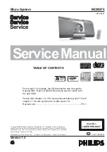


MCM298
/37/55
©
Copyright 2006 Philips Consumer Electronics B.V. Eindhoven, The Netherlands
All rights reserved. No part of this publication may be reproduced, stored in a retrieval system or
transmitted, in any form or by any means, electronic, mechanical, photocopying, or otherwise without
the prior permission of Philips.
Published by SL 0629 Service Audio
Printed in The Netherlands
Subject to modification
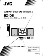
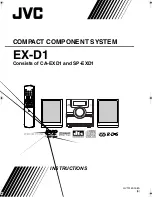
Micro System
Version 1.0
CLASS 1
LASER PRODUCT
©
3141 785 31140
TABLE OF CONTENTS
Page
Location of PC Boards & Versions Variation ........................ 1-2
Specifi cations ....................................................................... 1-3
Measurement Setup ............................................................. 1-4
Service Aids, Safety Instruction, etc ...........................1-5 to 1-7
Preparations & Controls ........................................... 1-8 to 1-11
Disassembly Instructions & Service positions ......................... 2
Service Test Program .............................................................. 3
Set Block Diagram ................................................................... 4
Set Wiring Diagram ................................................................. 5
Main Board .............................................................................. 6
ECO 6 Tuner Board : Systems Non Cenelec ........................ 7A
Power Board ............................................................................ 8
Display (MCU) Board............................................................... 9
Key Boards ............................................................................ 10
Set Mechanical Exploded View & Parts List .......................... 11
Summary of Contents for MCM298/37
Page 15: ...4 1 4 1 SET BLOCK DIAGRAM ...
Page 16: ...SET WIRING DIAGRAM 5 1 5 1 ...
Page 18: ...6 2 6 2 PCB LAYOUT MAIN BOARD TOP VIEW ...
Page 19: ...PCB LAYOUT DISPLAY BOARD BOTTOM VIEW 6 3 6 3 ...
Page 20: ...6 4 6 4 CIRCUIT DIAGRAM MAIN BOARD AUDIO PART ...
Page 21: ...6 5 6 5 CIRCUIT DIAGRAM MAIN BOARD CD PART ...
Page 22: ...6 6 6 6 PCB LAYOUT CLASS D POWER BOARD ...
Page 28: ...8 2 PCB LAYOUT ECO POWER BOARD 8 2 ...
Page 30: ...PCB LAYOUT DISPLAY BOARD TOP VIEW 9 2 9 2 ...
Page 31: ...9 3 9 3 PCB LAYOUT DISPLAY BOARD BOTTOM VIEW ...
Page 32: ...9 4 9 4 CIRCUIT DIAGRAM DISPLAY BOARD ...
Page 34: ...PCB LAYOUT KEY1 BOARD TOP VIEW 10 2 10 2 CIRCUIT DIAGRAM KEY1 BOARD ...
Page 35: ...10 3 10 3 PCB LAYOUT KEY2 BOARD CIRCUIT DIAGRAM KEY2 BOARD ...