background image

 MCM148

/55

©

 Copyright 2007 Philips Consumer Electronics B.V. Eindhoven, The Netherlands

All rights reserved.  No part of this publication may be reproduced, stored in a retrieval system or 
transmitted, in any form or by any means, electronic, mechanical, photocopying, or otherwise without 
the prior permission of Philips.

Published by SL 0731 Service Audio 

Printed in The Netherlands 

Subject to modification

Micro System

Version 1.0

CLASS 1

LASER PRODUCT

©

 3141 785 32030

TABLE OF CONTENTS

Page

Location of PCBs .................................................................. 1-2

Specifi cations ....................................................................... 1-3

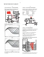
Measurement Setup ............................................................. 1-4

Service Aids, Safety Instruction, etc ..................................... 1-5

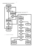
CD Playability Check ..................................................1-6 to 1-8

Software Version Checking ..................................................... 2

Set Block Diagram ................................................................... 3

Set Wiring Diagram ................................................................. 4

Main Board .............................................................................. 5

Front/MCU Board .................................................................... 6

Set Mechanical Exploded View & Parts List ............................ 7

Revision List ............................................................................ 9

Electrical Parts List .................................................................. 8

Summary of Contents for MCM148

Page 1: ...n of Philips Published by SL 0731 Service Audio Printed in The Netherlands Subject to modification Micro System Version 1 0 CLASS 1 LASER PRODUCT 3141 785 32030 TABLE OF CONTENTS Page Location of PCBs 1 2 Specifications 1 3 Measurement Setup 1 4 Service Aids Safety Instruction etc 1 5 CD Playability Check 1 6 to 1 8 Software Version Checking 2 Set Block Diagram 3 Set Wiring Diagram 4 Main Board 5 ...

Page 2: ...PCBS LOCATION FRONT BOARD MAIN BOARD 1 2 ...

Page 3: ...kHz Sensitivity FM 26 dB sensitivity 20 µV MW 26 dB sensitivity 5 mV m Total harmonic distortion İ5 SPEAKERS Bass reflex system Dimensions w x h x d 134 x 230 x 152 mm GENERAL INFORMATION AC Power 110 127 220 240V 50 60 Hz switchable Dimensions w x h x d 148 x 233 x 216 mm Weight with without speakers approx 3 65 1 53 kg Power consumption Active 15 W Standby 4 W Specifications and external appeara...

Page 4: ...z e g 7122 707 48001 LF Voltmeter e g PM2534 DUT S N and distortion meter e g Sound Technology ST1700B Frame aerial e g 7122 707 89001 Tuner AM MW LW To avoid atmospheric interference all AM measurements have to be carried out in a Faraday s cage Use a bandpass filter or at least a high pass filter with 250Hz to eliminate hum 50Hz 100Hz RF Generator e g PM5326 Ri 50Ω Bandpass 250Hz 15kHz e g 7122 ...

Page 5: ...ICE AIDS GB WARNING All ICs and many other semi conductors are susceptible to electrostatic discharges ESD Careless handling during repair can reduce life drastically When repairing make sure that you are connected with the same potential as the mass of the set via a wrist wrap with resistance Keep components and tools also at this potential ESD CLASS 1 LASER PRODUCT GB Safety regulations require ...

Page 6: ...ce CD Drive Laser current ok N Y check Laser current CD Drive offsets ok N Y check CD Drive offsets clean the lens check playability return set Customer complaint CD related problem return set return set replace CD Drive return set replace CD Drive return set replace Signal Processor return set fast lens cleaning 1 2 3 4 5 6 7 For flap loaders access to CD drive possible cleaning method 4 is recom...

Page 7: ...o contact the workshop directly The lens cleaning method 3 should be mentioned in the addendum sheet The final wording in national language as well as the printing is under responsibility of the Regional Service Organizations 3 FAST LENS CLEANING dry brush Use lens cleaning CD SBC AC300 9082 100 00043 Insert the lens cleaning CD press PLAY and follow the voice guide s instructions on the CD 4 LIQU...

Page 8: ... a DC Millivoltmeter directly on the connector see drawing below Pin numbering varies from drive to drive The values from diode A D should read 0 10mV Diodes E and F are less critical If one of the offsets is higher than 10mV the CD drive has to be replaced Otherwise replace the Signal Processor Sanyo DA12T3 CD Drive A A F C B E C D E VCC B VREF F D 9 10 11 12 13 14 15 16 1800 5V_HF VrefCD10 A D E...

Page 9: ...lugging in mains cord Display shows the ROM version VER y yy MTP xx xx 2007 VER refers to Version y yy refers to Software version number of the uProcessor counting up from 01 to 99 xx refers to date number of the production SOFTWARE VERSION CHECKING ...

Page 10: ...3 1 3 1 SET BLOCK DIAGRAM ...

Page 11: ...FRONT MCU SET WIRING DIAGRAM 4 1 4 1 ...

Page 12: ...MAIN BOARD TABLE OF CONTENTS Layout Top View 5 2 Layout Bottom View 5 3 Circuit Diagram AF Amp Part 5 4 Circuit Diagram CD MP3 Part 5 5 Circuit Diagram Tuner Part 5 6 5 1 5 1 ...

Page 13: ...5 2 5 2 PCB LAYOUT MAIN BOARD TOP VIEW ...

Page 14: ...5 3 5 3 PCB LAYOUT MAIN BOARD BOTTOM VIEW ...

Page 15: ...5 4 5 4 CIRCUIT DIAGRAM MAIN POWER BOARD AF AMP PART ...

Page 16: ...5 5 5 5 CIRCUIT DIAGRAM MAIN BOARD CD MP3 PART ...

Page 17: ...5 6 5 6 CIRCUIT DIAGRAM MAIN BOARD TUNER PART ...

Page 18: ...FRONT MCU BOARD TABLE OF CONTENTS Layout Top View 6 2 Layout Bottom View 6 3 Circuit Diagram 6 4 6 1 6 1 ...

Page 19: ...6 2 PCB LAYOUT FRONT MCU BOARD TOP VIEW 6 2 ...

Page 20: ...6 3 PCB LAYOUT FRONT MCU BOARD BOTTOM VIEW 6 3 ...

Page 21: ...6 4 CIRCUIT DIAGRAM FRONT MCU BOARD 6 4 ...

Page 22: ...104 108 115 101 115 111 117 113 130 116 131 114 112 103 106 80 T101 102 SET MECHANICAL EXPLODED VIEW 7 1 7 1 ...

Page 23: ...N 114 996510006664 MODE PROG BUTTON 115 996510006665 DISPLAY LENS SAN 116 996510007596 PLAY BUTTON COVER 117 996510007595 STOP BUTTON COVER 119 996510000911 CD DAMPER BLACK 120 996510000912 CD DAMPER GREY 125 994000003674 CD DOOR SPRING 130 996510007570 SOURCE BUTTON COVER 131 996510007571 DBB BUTTON COVER J001 994000004487 16P FFC 1MM L 170MM J002 996510000914 17P FLAT FLEX CABLE 1 25mm J006 9965...

Page 24: ...3 15A 250V FMANT1 996510002038 FM ANT CONTACT PIN IC2 996500039806 IC ET2314 SOP28 IC802 994000004622 IC LA6548NH JACK1 994000004369 PHONE JACK TC38 063 05 0 JACK2 996510000889 PHONE JACK TC38 060 01 RING L28 996510000887 FM COIL 3x19 5T L29 996510000888 FM COIL 5x3 5T L30 994000003646 AXIAL INDUCTOR 10UH 10 500MA L31 996500039350 FM COIL 4 5x2 5T 0 8mm L32 996510000888 FM COIL 5x3 5T L801 9965100...

Page 25: ...2 996500042444 TACT SWITCH 6x6mm 4 3mm SW13 996500042444 TACT SWITCH 6x6mm 4 3mm SW2 996500042444 TACT SWITCH 6x6mm 4 3mm SW3 996500042444 TACT SWITCH 6x6mm 4 3mm SW4 996500042444 TACT SWITCH 6x6mm 4 3mm SW5 996500042444 TACT SWITCH 6x6mm 4 3mm SW6 996500042444 TACT SWITCH 6x6mm 4 3mm SW7 996500042444 TACT SWITCH 6x6mm 4 3mm SW8 996500042444 TACT SWITCH 6x6mm 4 3mm SW9 996500042444 TACT SWITCH 6x6...

Reviews: