background image

Summary of Contents for LDTS07

Page 1: ......

Page 2: ...s is a Philips Controls brand This manual is for informational use only and is subject to change without notice Lightolier Controls assumes no responsibility or liability for any claims resulting from errors or inaccuracies that may appear in this manual Version as of July 6 2009 Document 85 6369A0 Lytemode Designer Suite Touch Screen User s Guide 2009 Philips Controls All Rights Reserved ...

Page 3: ...r Suite System 2 Designer Suite Touch Screen Overview 3 Installation 4 LDTS07 Wall Mount 4 LDTS07RM Rack Mount 5 Setup and Operation 6 Customer Service Technical and Sales assistance for Lytemode products are available worldwide Phone 1 800 526 2731 In the United States and Canada 1 214 647 7880 Worldwide ...

Page 4: ...er and more By combining Lytemode Designer Suite Slider Stations Lytemode Designer Suite Button Stations and Lytemode Designer Suite Touch Screens the system provides remote access to scenes master raise lower control multi room partition control station lockout toggle on off smart matrix commands and more Lytemode Designer Suite Stations are compatible with Lyteswitch Capio Plus Optio and Intelli...

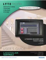
Page 5: ...ny selected station Access to programmable pushbuttons and channel adjustments can be made with just a few simple touches of the screen The following Touch Screen models are covered in this manual LDTS07 7 Full Color VGA Touch Screen Wall Mount LDTS07RM 7 Full Color VGA Touch Screen Rack Mount All models feature a Real Time Clock which allows a large number of lighting events to coincide with spec...

Page 6: ...h appropriate knock out hole and install rough in box sold separately into wall Figure 1 Step 3 Connect ILS network cable to Touch Screen ILS connector Step 4 Install Touch Screen onto rough in box using four 6 flat head screws Figure 1 Installing LDTS07 Wall Mount Touch Screen Rough In Box Knock Out Hole Touch Screen Assembly Wall Mount Version ILS 9 Pin Connector From ILS Network Part ILSCLBTSII...

Page 7: ...unting hardware Figure 2 Installing LDTS07RM Rack Mount Touch Screen Touch Screen Unit Rack Mount Version Rack Mount Screw 4 ILS 9 Pin Connector 1 WH OR Data 2 OR Data 3 SHIELD 4 WH GN Volts 5 GN Ground 6 WH BL Volts 7 BL Ground 8 WH BR Volts 9 BR Ground PIN SIGNAL WARNING Remove power from house service before connecting any wiring or cables to the Designer Suite Touch Screen From ILS Network TOP...

Page 8: ...tion The Lytemode Designer Suite Touch Screen is programmed using Lytemode Designer Suite Software The software runs on a PC connected by an ILSCL232 Interface to the Designer Suite system For specific programming instructions refer to the Lytemode Designer Suite Software manual ...

Page 9: ...with removal and re installation of the product and shipping to Philips Controls or its authorized supplier PHILIPS CONTROLS LIMITS THE DURATION OF THE IMPLIED WARRANTY OF MERCHANTABILITY WITH RESPECT TO THE PRODUCT TO THE LIMITED WARRANTY PERIOD SET FORTH ABOVE AND OTHERWISE DISCLAIMS ALL IMPLIED WARRANTIES WITH RESPECT TO THE PRODUCT AND ITS PARTS Some states disallow certain limitations on impl...

Page 10: ......

Reviews: