background image


1 - 1 

DVD Home Theater System 


Service


HTS3021

/98/94 


TABLE OF CONTENTS


Chapter  

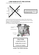
LASER BEAM SAFETY PRECAUTIONS................................................................................................1-2   

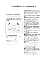
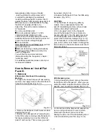
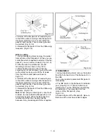
STANDARD NOTES FOR SERVICING........................................................................

.................1-3  

SAFETY AND IMPORTANT NOTICE......................................................................................................1-7 

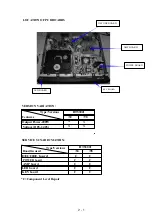
LOCATION OF PCB BOARDS

VERSION VARIATION .....................................................................2-1 

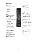
REMOTE CONTROL........................................................................................…………...…...................2-2  

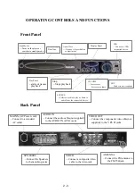
OPERATING CONTROLS AND FUNCTIONS ...........................................................……...............…..2-3 

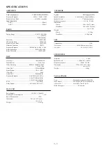
SPECIFICATIONS ......................................................................................................................................3-1 

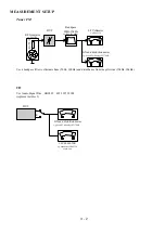
MEASUREMENT SETUP………………..................................................................................

.................... 3-2   .

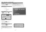
SYSTEM,REGION CODE,ETC..SETTING PRODURE............................................

....................3-3  

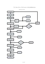
RETURN UNIT TEST FLOW......................................................................................................................3-4


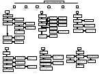
MAIN UNIT REPAIR CHART....................................................................……………................………3-5 

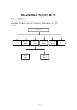
DISASSEMBLY INSTRUCTIONS ............................................................................................................4   

BLOCK WIRING DIAGRAM.....................................................................................................................5 

AMPLIFIER BOARD

LED +   KEY BOARD

DECODE BOARD

POWER BOARD......................6   

MECHANICAL EXPLODE VIEW

PART LIST......................................................................................10   

REVISION LIST………………………………………………….....……………………………..............11 


©

 Copyright 2009 Philips Consumer Electronics B.V. Eindhoven, The Netherlands 

All rights reserved.      No part of this publication may be reproduced, stored in a retrieval system or   

transmitted,  in  any  form  or  by  any  means,  electronic,  mechanical,  photocopying,  or  otherwise 

without the prior permission of Philips.   

Published by LM0909 Service Audio Printed in    The Netherlands Subject to modification   

Version 1.0 

GB 

3139 785 3

483 0  

Service Manual

............

...........

Summary of Contents for HTS3021/94

Page 1: ...CHART 3 5 DISASSEMBLY INSTRUCTIONS 4 BLOCK WIRING DIAGRAM 5 AMPLIFIER BOARD LED KEY BOARD DECODE BOARD POWER BOARD 6 MECHANICAL EXPLODE VIEW PART LIST 10 REVISION LIST 11 Copyright 2009 Philips Consumer Electronics B V Eindhoven The Netherlands All rights reserved No part of this publication may be reproduced stored in a retrieval system or transmitted in any form or by any means electronic mechan...

Page 2: ... location shown in the figure When checking the laser diode be sure to keep your eyes at least 30 cm away from the pickup lens when the diode is turned on Do not look directly at the laser beam CAUTION Use of controls and adjustments or doing procedures other than those specified herein may result in hazardous radiation exposure CAUTION LASER RADIATION WHEN OPEN DO NOT STARE INTO BEAM Location Top...

Page 3: ...is not easy to store and to handle Use only adequate solder tools applicable for leadfree solder alloy The solder tool must be able To reach at least a solder temperature of 400 C To stabilize the adjusted temperature at the solder tip To exchange solder tips for different applications Adjust your solder tool so that a temperature around 360 C 380 C is reached and stabilized at the solder joint He...

Page 4: ...S 1 1 2 Remove the flat pack IC with tweezers while applying the hot air 3 Bottom of the flat pack IC is fixed with glue to the CBA when removing entire flat pack IC first apply soldering iron to center of the flat pack IC and heat up Then remove glue will be melted Fig S 1 6 4 Release the flat pack IC from the CBA using tweezers Fig S 1 6 CAUTION 1 The Flat Pack IC shape may differ by models Use ...

Page 5: ...f the flat pack IC is fixed with glue to the CBA when removing entire flat pack IC first apply soldering iron to center of the flat pack IC and heat up Then remove glue will be melted Fig S 1 6 5 Release the flat pack IC from the CBA using tweezers Fig S 1 6 Note When using a soldering iron care must be taken to ensure that the flat pack IC is not being held by glue When the flat pack IC is remove...

Page 6: ... through the body grounding band be careful to avoid contacting semi conductors with your clothing Instructions for Handling Semiconductors Electrostatic breakdown of the semi conductors may occur due to a potential difference caused by electrostatic charge during unpacking or repair work 1 Ground for Human Body Be sure to wear a grounding band 1 M that is properly grounded to remove any static el...

Page 7: ... if disassembled by a specialized company If you are disposing of an old machine please take it to a recycling center Please observe the local regulations regarding disposal of packaging materials exhausted batteries and old equipment Copyright notice This product incorporates copyright protection technology that is protected by method claims of certain U S patents and other intellectual property ...

Page 8: ...s Output Power 200W Voltage 110V 240V SERVICE SCNARIO MATRIX Type Versions Board in used 94 Χ Χ HTS3021 98 Χ Χ HTS3021 94 98 DECODE BOARD KEY BOARD AMP BOARD POWER BOARD DECODE board C C POWER board C C AMP board C C LED board C C KEY board C C C Component Level Repair 2 1 ...

Page 9: ...ects an audio language or channel on a disc Press and hold to access the setting for audio sync then press VOL to set the audio delay time Numeric buttons Selects an item to play SUBTITLE Selects the subtitle language on a disc VOCAL Changes the audio channel of a karaoke disc MIC VOL Increases or decreases microphone volume REPEAT PROGRAM Selects or turns off repeat or shuffl e mode In radio mode...

Page 10: ... to play or listen to audio from the connected device Back Panel VOLUME Increases or decreases volume MIC Connects a microphone MAINS AC Power cord Connect to a standard AC outlet SPEAKERS AUDIO IN Connect the audio cables not supplied to the AUDIO IN_AUX1 jacks VIDEO VIDEO OUT Connect the component video cable not supplied to the Y Pb Pr jacks ANTENNA Connect the Speakers to the matching jacks Co...

Page 11: ...Hz 4 Hz 44 kHz 96 kHz PCM IEC 60958 Dolby Digital IEC 60958 IEC 61937 MAIN UNIT Power Supply 110 240 V 50 60Hz Standby power consumption 1W Power Consumption 50 W Dimensions 360 x 48 x 332 mm w x h x d Weight 2 64 kg SPEAKERS System Full range satellite Speaker impedance 8 ohm centre 4 ohm Front Rear Speaker drivers 3 full range speaker Frequency response 150 Hz 20 kHz Dimensions Center 100 x 100x...

Page 12: ...stortion meter e g Sound Technology ST1700B Use a bandpass filter to eliminate hum 50Hz 100Hz and disturbance from the pilottone 19kHz 38kHz CD Use Audio Signal Disc replaces test disc 3 DUT L R SBC429 4822 397 30184 S N and distortion meter e g Sound Technology ST1700B LEVEL METER e g Sennheiser UPM550 with FF filter Ri 75Ω 3 2 ...

Page 13: ...ch off to standby automatically after update is complete e OSD will show Current model HTS3021 98 Ver18 04 2M _090211_0 Region 3 Servo AE 56 00 00 8032 05 00 04 06 RISC 05 02 00 24 IF current model does not match you set use down arrow key on the remote to change OK CAUTION This information is confidential and may not be distributed Only a qualified service person should reprogram the Region Code ...

Page 14: ...3 4 ...

Page 15: ...k open close and disc change working or not Re insert and fix the cable Hae picture output Yes or No Check IC u102 AND con100 its conjoint part Check cn102 cn101and cn105 to dvd loader cable loose or bad int Check U102 and their cojoint part Check cn102 to DVD loader loose or bad not Check ic804 their conjoint part Check repair Between ic801 E Aux TV in No Sound Tuner NO Sound Check U109 and its c...

Page 16: ...tes the disassembly steps to gain access to item s to be serviced When reassembling follow the steps in reverse order Bend route and dress the cables as they were originally Top Case Loader Decode Board Led Board Front Panel Power Board Key Board Amplifier Board Tuner 4 1 ...

Page 17: ... Ensure no disc in the tray and keep tray close turn off the DVD player and then disconnect the mains supply Loosen 6 screws A as shown in figure 2 1 A Figure 2 1 2 2 Take off the top case as shown in figure 2 2 OPEN Figure 2 2 4 2 ...

Page 18: ...3 Dismantling of 3 1 Loosen 4 screws B as shown in figure 3 1 Figure 3 1 B 4 3 led key board ...

Page 19: ...3 2 Release the lock C at the same time as shown figure 3 2 Figure 3 2 3 3 Loosen 5 screws D as shown in figure 3 3 Figure 3 3 C PUSH PUSH PUSH PUSH PUSH D 4 4 ...

Page 20: ...4 Dismantling of loader 4 1 Loosen 4 screws E as shown in figure 4 1 E Figure 4 1 4 5 ...

Page 21: ...5 Dismantling of dec ode board 5 1 Loosen 5 screws as shown in figure 5 1 Figure 5 1 6 Dismantling of power board 6 1 Loosen 4 screws G as shown in figure 6 1 Figure 6 1 F G 4 6 ...

Page 22: ...7 Dismantling of amplifier board 7 1 Loosen 4 screw H as shown in figure 7 1 Figure 7 1 H 4 7 ...

Page 23: ...8 Dismantling of tuner 8 1 Loosen 1 screws I as shown in figure 8 1 Figure 8 1 9 Dismantling of L ed board 9 1 Loosen 2 screws J as shown in figure 9 1 Figure 9 1 I J 4 8 ...

Page 24: ...5 1 C4 C2 C1 C3 C5 C6 C7 C8 C10 C11 C13 C12 BLOCK WIRING DIAGRAM C9 ...

Page 25: ...6 1 AMPLIFIER BOARD SCHEMATIC DIAGRAM 1 3 ...

Page 26: ...6 2 AMPLIFIER BOARD SCHEMATIC DIAGRAM 2 3 ...

Page 27: ...6 3 AMPLIFIER BOARD SCHEMATIC DIAGRAM 3 3 ...

Page 28: ...6 4 AMPLIFIER BOARD TOP VIEW ...

Page 29: ...6 5 AMPLIFIER BOARD BOTTOM VIEW ...

Page 30: ...26 39 38 37 36 35 34 33 32 31 30 29 28 27 14 7 PIN OUT SDA SCK STB K1 K2 K3 SG1 KS1 SG2 KS2 SG4 KS4 SG5 K4 SG11 SG10 SG9 SG3 KS3 SG8 SG7 SG6 ROMETO MODE RESET OSC1 GR5 GR4 GR3 GR2 GR1 VDD PSW GPIO4 GPIO3 GPIO2 GPIO1 GND OSC2 SG12 GR6 GR7 GR8 SG20 GR9 SG19 GR10 VEE VDD SG18 GR11 SG17 GR12 SG16 GR13 SG15 GR14 SG14 GR15 SG13 GR16 VDD SCL CB537 ESD J510 3 2 5 HEADER 1 2 3 CB528 ESD NC R536 0 R514 1K J...

Page 31: ...7 2 LED BOARD TOP VIEW KEY BOARD TOP VIEW LED KEY BOARD TOP VIEW ...

Page 32: ...LED BOARD BOTTOM VIEW KEY BOARD BOTTOM VIEW 7 3 LED KEY BOARD BOTTOM VIEW ...

Page 33: ...120P C209 15p ZD109 ESD0603 SMD R300 NC 0 U113 NC PI5V330W 1 2 3 4 5 6 7 8 9 10 11 12 13 14 15 16 IN S1A S2A DA S1B S2B DB GND DC S2C S1C DD S2D S1D EN VCC Q124 NC 2N3904 1 3 2 R318 100 CB170 0 1uF C204 220uF 16V L165 FB Q121 2N3906 1 3 2 CE133 220uF 16v L171 FB R299 75 1 CE127 22uF 16v C198 15p D113 1N4148 C210 47p R301 NC 0 L169 FB D109 DIODE SMD BAV99 1 3 2 R326 470 R319 75 1 C192 120P L162 0 2...

Page 34: ...82 4 7K L147 FB R288 10K C184 33P R294 8 2K C190 1000P R290 13K EC130 100U 16v R297 NC 15K C188 33P U112A NJM4558 3 2 1 8 4 L153 FB C189 33P C186 33P CB166 0 1u C185 33P C187 33P R293 68K R280 1K C182 1000P CN111 TUNER PORT KST 6A 1 2 4 6 7 8 9 10 3 5 R285 10K R291 NC 15K EC132 10u R281 10K R283 68K R286 10K Q114 8550 1 3 2 L151 FB L149 FB U112B NJM4558 5 6 7 8 4 L152 FB C183 47P C181 47P L150 FB ...

Page 35: ...C165 1uF R262 1 8K NC R182 0R U111B NJM4558 5 6 7 8 4 R186 4 7K R232 NC R198 1K L137 FB R370 12k ZD103 ESD0603 SMD R217 100K C164 100P CN110 IPOD 1 2 3 4 5 6 7 8 9 EC122 10UF 10v R193 47 C177 47P R215 5 1 L141 FB R246 470 R277 10K R371 47k C161 0 1u R220 100k R178 0R EC127 4U7 0805 C159 470p R202 4 7K R226 4 7K R245 10K L142 FB R195 470 1 2 R204 100K CB160 0 1u C168 1uF R184 0R U107 74HC4051 1 2 1...

Page 36: ...PWR 2 89_PRD 2 89_A 0 20 2 DV33 1 2 5 6 7 DV33_FLASH 89_SD33 DV33 DV33 89_SD33 DV33_FLASH DV33 DV33 89_SD33 DV33_FLASH DV33 R172 10k R167 33 L127 FB U104 A641604L 6 7TE TSOP II 54 SMD 1 2 4 12 5 7 9 8 10 46 11 13 15 16 17 18 19 35 22 23 24 25 26 14 41 29 30 31 32 33 34 36 37 38 39 40 43 42 44 52 45 47 49 48 50 51 53 54 20 21 3 6 27 28 VCC DQ0 DQ1 VSSQ DQ2 DQ3 VCCQ DQ4 DQ5 VSSQ DQ6 DQ7 DQML WE CAS ...

Page 37: ...190 189 188 187 186 185 184 183 182 181 180 179 178 177 176 175 174 173 172 171 170 169 167 168 166 165 164 163 162 161 160 159 158 156 157 155 154 153 152 151 150 148 149 147 146 145 144 143 141 142 140 139 138 137 136 134 135 133 132 131 130 249 255 24 254 231 230 238 237 248 247 236 251 246 243 241 242 240 239 234 235 232 224 225 222 221 220 219 226 218 217 215 213 214 204 211 210 209 208 212 2...

Page 38: ...05 0 1uF R105 300 1 L112 FB R100 100 L101 FB 1A R114 10 L105 FB R102 NC 470 1 2 L113 FB CE103 47uF 16v R110 10k R104 0 1 2 EC109 10uF 16v C10UF16V D5H11 L110 FB EC100 10uF 16v EC104 10uF 16v CB132 0 1uF L103 NC FB EC107 470UF16V L108 FB C102 1uF NC Q101 8050 DIP 1 3 2 EC106 100UF16V CB118 0 1uF L102 FB L100 FB R107 470 C108 22pF CB131 0 1uF CB122 0 1uF CB125 0 1uF CE101 100uF R103 680 1 C109 22pF ...

Page 39: ...8 7 DECODE BOARD TOP VIEW ...

Page 40: ...8 8 DECODE BOARD BOTTOM VIEW ...

Page 41: ... C937 104 50V L906 5U 7A IC907 KA431 R926 2 2K 0 25W R929 22K 0 25W R927 47K 0 25W R930 430K 0 25W C938 104 50V R931 2 2K 0 25W ZD903 18V VCC VCC B 1 E 3 C 2 Q906 C1815 L903 100UH C919 47UF 10V R911 1K 0 25W 24V 12V 0 1A 12V 0 15A 32V 5A B 1 E 3 C 2 Q905 C1815 R932 10K 0 25W R933 10K 0 25W ZD904 36V C929 471 1KV V R924 33R 2W C934 47P 1KV C923 47P 1KW R914 33R 1W D912 SB340 C942 NC R928 680K 0 25W...

Page 42: ...9 2 POWER BOARD TOP VIEW ...

Page 43: ...9 3 POWER BOARD BOTTOM VIEW ...

Page 44: ...10 1 MECHANICAL EXPLODE VIEW ...

Page 45: ...OP CASE SPCC BLACK 80301 NO D 3 996510021711 FRONT LENS PMMA BLACK 80248 TR 4 996510022329 CD DOOR ABS BLACK 80301 HTS30 5 996510021707 RUBBER FOOT 6 996510021702 INSULATED PLATE BOTTOM BLACK 7 996510021709 BOTTOM CASE SECC C1 996510021699 FILM FLAT CABLE 24 PIN PITCH 0 C11 996510021725 HOUSING 05 2 5 HOUSING 05 2 C12 996510021697 FILM FLAT CABLE 24 PIN PITCH 0 C2 996510021729 FILM FLAT CABLE 10 P...

Page 46: ...0V 5X20MM IC901 996510022249 I C FSQ110 FAIRCHILD FAIRCHIL IC902 996500040601 I C PC817C PHOTOCOUPLER IC903 996510006016 I C KA431Z FAIRCHILD IC904 996510022197 I C FSCQ1265RT FAIRCHILD QUAS IC905 996500040601 I C PC817C PHOTOCOUPLER IC906 996500040601 I C PC817C PHOTOCOUPLER IC907 996510006016 I C KA431Z FAIRCHILD L901 996510022256 AC LINE FILTER 20MHX2 LCL 20 2 L902 996510022256 AC LINE FILTER 2...

Page 47: ...8 SNRD LS4148 150mA 100V 3 5 X D508 996510022228 SNRD LS4148 150mA 100V 3 5 X D509 996510022228 SNRD LS4148 150mA 100V 3 5 X IR501 996510022211 INFRARED RECEIVER MODULE 36KHZ J502 996510022183 HOUSING 1 PIN 100MM WIRE UL100 J515 996510022248 EARPHONE SOCKET 3 6MM PJ 3 5 3 Q501 996510022195 I CI IMP810SEUR T IMP RESET I SW1 996510022201 TSVT H 5mm KPT 1105A 4 PINS SW2 996510022201 TSVT H 5mm KPT 11...

Page 48: ...8mm L112 996510022193 SMD FERRITE BEAD 1 6 X 0 8mm L113 996510022193 SMD FERRITE BEAD 1 6 X 0 8mm L114 996510022193 SMD FERRITE BEAD 1 6 X 0 8mm L115 996510022193 SMD FERRITE BEAD 1 6 X 0 8mm L116 996510022216 SMD FERRITE BEAD 2 X 1 25mm L117 996510022173 PEAKING COIL 150UH 10 TAPE L119 996510022207 PEAKING COIL 47uH 10 TAPE L120 996510022216 SMD FERRITE BEAD 2 X 1 25mm L121 996510022216 SMD FERRI...

Page 49: ... TRANSISTOR PSS8550 PHILIPS TA Q115 996510022202 TRANSISTOR 2N3904 PNP TO 92 TA Q117 996500041188 TRANSISTOR SST3906 MMBT3906 PM Q118 996500041187 TRANSISTOR SST3904 MMBT3904 PM Q119 996500041187 TRANSISTOR SST3904 MMBT3904 PM Q120 996500041188 TRANSISTOR SST3906 MMBT3906 PM Q121 996500041188 TRANSISTOR SST3906 MMBT3906 PM U100 996510022212 I C CX117 ADJ SILICON CORD R U101 996510022245 SMD IC APL...

Page 50: ...V 3 5 X IC801A 996510022229 SMD IC STA518 ST 40V 3 5A QUAD IC801B 996510022229 SMD IC STA518 ST 40V 3 5A QUAD IC803 996510022236 I C TJM4558CD SGS WIDE BANDW IC804 996510022237 SMD IC STA309A ST TQFP 64 JK801A 996510022215 RCA JACKX3 H HYPE PITCH 15MM R JK801B 996510022251 RCA JACKX3 H HYPE PITCH 15MM R L801A 996510022161 CHOKE COIL 22UH 15 10 5MM X1 L801B 996510022161 CHOKE COIL 22UH 15 10 5MM X1...

Page 51: ...REVISION LIST Version 1 0 Initial release 11 1 ...

Reviews: