background image

©

 Copyright 2010 Philips Consumer Electronics B.V. Eindhoven, The Netherlands

All rights reserved.  No part of this publication may be reproduced, stored in a retrieval system or 
transmitted, in any form or by any means, electronic, mechanical, photocopying, or otherwise without 
the prior permission of Philips.


Version 1.

0

Version 0.0

LASER PRODUCT

©

TABLE OF CONTENTS

Page

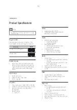
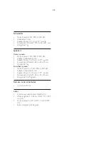
Production Specifications ...............................................................................................1-3

D      Instruction................................................................................................................2-1
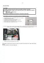
Mechanical and Dismantling Instructions ........................................................................3-1

Software Upgrades...........................................................................................................  -1
Trouble Shooting Chart ....................................................................................................  -1

Set Mechanical Exploded view  .......................................................................................  -1
Revision List ...................................................................................................................

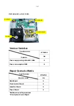
Location of PCB Boards & version variation & repair scenario matrix.....................

1-2

CLASS 1


GB

3

139

78536

22

0

Published by Helen-RY 1216  Service Audio Printed in The Netherlands Subject to modification

Wiring Diagrams ................................................................................................6-1

Electrical Diagrams and Print-layouts .................................................................7-1

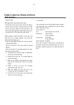
Safety Instruction, Warning & Notes................................................................................1-

8

9

-1

Version 1.0

7

Home Theater DVD Player


FU

4
5

Service


HTS

2

5

12

/

94

GB

Summary of Contents for HTS2512/94

Page 1: ...CONTENTS Page Production Specifications 1 3 D Instruction 2 1 Mechanical and Dismantling Instructions 3 1 Software Upgrades 1 Trouble Shooting Chart 1 Set Mechanical Exploded view 1 Revision List Location of PCB Boards version variation repair scenario matrix 1 2 CLASS 1 GB 313978536220 Published by Helen RY 1216 Service Audio Printed in The Netherlands Subject to modification Wiring Diagrams 6 1 E...

Page 2: ...240V 50Hz X Power consumption 55W X Repair Scenario Matrix HTS2512 Type Versions Board in used 94 Main Board C Front Control Board C Amplifier Board C Power Board C Bd Board Level Replacement C Component Level Repair AV BOARD MAIN BOARD LOADER POWER BOARD 1 2 PCB BOARD LOCATION ...

Page 3: ...tem PAL NTSC Component video output 480i 576i 480p 576p 720p 1080i Audio S PDIF Digital audio input Coaxial IEC 60958 3 Optical TOSLINK Sampling frequency MP3 32 kHz 44 1 kHz 48 kHz WMA 44 1 kHz 48 kHz Constant bit rate MP3 32 kbps 320 kbps WMA 128 bps 192 kbps Radio Tuning range Europe Russia China FM 87 5 108 MHz 50 kHz Asia Pacific Latin America FM 87 5 108 MHz 50 100 kHz Signal to noise ratio F...

Page 4: ... x 70 mm 2 75 woofer Dimensions WxHxD 84 5 x 89 x 89 mm Weight 0 27 kg Front Rear speaker Output power 4 x 50 W RMS 30 THD Speaker impedance 4 ohm Speaker drivers 1 x 70 mm 2 75 woofer Dimensions WxHxD 84 5 x 89 x 89mm Weight 0 25 0 29 kg each Remote control batteries 2 x AAA R03 1 5V Laser Type Semiconductor laser GaAIAs CD Wave length 645 665 nm DVD 770 800 nm CD Output power 6 mW DVD 7 mW VCD C...

Page 5: ... wire between the two pins of the mains plug 2 Set the mains switch the on position keep the mains cord unplug 3 Measure the resistance value between the mains plug and the front panel controls and chassis bottom 4 Repair or correct unit when the resistance measurement is less than 1M 5 Verify this before you return the unit to the customer user ref UL standard no 1492 6 Switch the unit off and re...

Page 6: ...ch copper tracks and or components in this unshielded primary area when you service the player Service personnel must take precautions to prevent touching this area or components in this area A lighting stroke and a stripe marked printing on the printed wiring board indicate the primary side of the power supply Never replace modules or components while the unit is on 2 Laser The use of optical ins...

Page 7: ...WV J 5HSODFH WKH GHIHFWLYH ORDGHU ZLWK D QHZ ORDGHU 5HPRYH SDSHUFOLS IURP WKH ÀH IRLO DQG FRQQHFW LW WR WKH QHZ ORDGHU 5HPRYH VROGHU MRLQW RQ WKH 6 SURWHFWLRQ SRLQW 77 17 21 7KH ODVHU GLRGH RI WKLV ORDGHU LV SURWHFWHG DJDLQVW 6 E D VROGHU MRLQW ZKLFK VKRUWFLUFXLWV WKH ODVHUGLRGH WR JURXQG RU SURSHU IXQFWLRQDOLW RI WKH ORDGHU WKLV VROGHU MRLQW PXVW EH UHPRYH DIWHU FRQQHFWLRQ ORDGHU WR WKH VHW 2QO D...

Page 8: ...ch off un used equipment or reduce heat x Mix of lead free solder alloy parts with leaded solder alloy parts is possible but PHILIPS recommends strongly to avoid mixed solder alloy types leaded and lead free If one cannot avoid clean carefully the solder joint from old solder alloy and re solder with new solder alloy SAC305 x Use only original spare parts listed in the Service Manuals Not listed s...

Page 9: ...osan olvassa el a mellékelt biztonsági tudnivalókat IT Prima di utilizzare il prodotto leggere tutte le relative informazioni sulla sicurezza NL Lees voordat u het product gaat gebruiken eerst alle bijbehorende veiligheidsinformatie NO Lees voordat u het product gaat gebruiken eerst alle bijbehorende veiligheidsinformatie PL Przed rozpoczĔciem korzystania z produktu naleůy zapoznaĂ siĔ z informacj...

Page 10: ...s Home Entertainment Systems EL ƓƵƭƤƝƳƴƥ ƴƯ home cinema ES Conecta el sistema de cine en casa FI Kotiteatterin liitännät FR Connecter les enceintes au Home Cinéma HU A házimozi csatlakoztatása IT Collegamento del sistema HomeTheater NL Sluit de home cinema aan NO Koble til hjemmekinoanlegget PL PodãĀczanie zestawu kina domowego PT Efectuar as ligações ao sistema de cinema em casa RO Conectaŗi sist...

Page 11: ...lakummalla tavalla FR Connectez vous au téléviseur via l une de ces méthodes HU Csatlakoztassa a tv készülékhez az alábbi módok egyike szerint IT Esegui il collegamento alTV in uno dei modi indicati di seguito NL Maak op een van de volgende manieren verbinding met deTV NO Koble tilTVen på en av følgende måter PL PodãĀcz do telewizora przy uůyciu jednej z tych metod PT Ligar ao televisor de uma des...

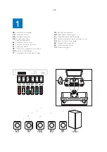
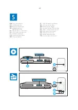
Page 12: ...AUDIO L R R L AUDIO IN L R AUDIO OUT VIDEO AUDIO L R VIDEO OUT VIDEO IN 2 4 ...

Page 13: ...cine en casa FI Virran kytkeminen kotiteatteriin FR Mettre sous tension le Home Cinéma HU A házimozi bekapcsolása IT Accensione del sistema HomeTheater NL Schakel de home cinema in NO Slå på hjemmekinoanlegget PL WãĀczanie zestawu kina domowego PT Ligar o sistema de cinema em casa RO Porniŗi sistemul home theater SK Zapnutie domáceho kina SV Sätt på hemmabiosystemet TR Ev sinemasını açın 2 5 ...

Page 14: ...ßen der Ersteinrichtung EL ƐƫƯƪƫƧƱƾƳƴƥ ƴƧ ƱƽƨƬƩƳƧ ƣƩơ ưƱƾƴƧ ƶƯƱƜ ES Finaliza la configuración inicial FI Ensiasennuksen suorittaminen loppuun FR Effectuer la configuration initiale HU Az elsʼn üzembe helyezés IT Completamento della configurazione iniziale NL Voltooi de eerste installatie NO Fullføre den første konfigureringen PL Pierwsza konfiguracja PT Executar a configuração inicial RO Realizaŗi prima ...

Page 15: ...e en casa FI Kotiteatterin käyttäminen FR Utiliser votre Home Cinéma HU A házimozi használata IT Utilizzo del sistema HomeTheater NL Uw home cinema bedienen NO Bruke hjemmekinoanlegget PL Korzystanie z zestawu kina domowego PT Utilizar o sistema de cinema em casa RO Utilizaŗi sistemul home theater SK Používanie domáceho kina SV Använda hemmabiosystemet TR Ev sinema sisteminin kullanılması 2 7 ...

Page 16: ...2 1 2 8 ...

Page 17: ...lay panel c Open Close Open or close the disc compartment or eject the disc d Play Pause Start pause or resume play e SOURCE Select an audio or video source for the home theater f Standby On Switch the home theater on or to standby Connectors This section includes an overview of the connectors available on your home theater Remote control This section includes an overview of the remote control 1 2...

Page 18: ... camera angels m REPEAT PROGRAM Select or turn off repeat mode In radio mode press once to access program mode and press again to store the radio station In radio mode press and hold for three seconds to reinstall the radio stations n REPEAT A B Mark two points within a chapter or track to repeat play or turn off the repeat mode o ZOOM Zoom into a video scene or picture Press the Navigation button...

Page 19: ...der or Front Panel the Front door should be removed first Figure 2 Note Make sure to operate gently otherwise the guider would be damaged Figure 2 3 1 Please kindly note that dismantle the front door assembly carefully to avoid damage tray and the front door Detailed information please refer to the model set Turn on the power button then press open button to dismantle front door Please kindly note...

Page 20: ...ase refer to the model set Figure 3 Step5 that connects the loader and the bottom cabinet Figure 5 Dismantle Loader disconnect the 3 connectors XP9 XP2 XP8 aiming in the below figure and remove 2 screws Figure 4 Figure 5 Dismantle Front Panel disconnect the connectors XP22 XP33 need release 2 snaps of Front Panel 2 snaps Dismantle Front Control Board remove 5 screws Figure 4 ...

Page 21: ...tep6 Step7 Step8 Dismantle AV Board first disconnect 1 connector XP11 and then remove Dismantle Main Board first disconnect 1 connector XP36 and then remove 7 screws Figure 5 6 Dismantle Power Board disconnect the connectors XP3and XS703 then remove 5 screws Figure 5 6 Figure 5 6 3 screws XP11 XP2 XS703 XP36 XP9 XP8 XP33 XP3 XP22 ...

Page 22: ...ntil the player reset automatically the whole upgrade process may need 2 minutes HTS will auto standby after complete upgrade if you upgrade with USB device 1 step1 is same with DISC upgrade 2 Copy the renamed bin file upgrade file to the root menu of USB device 3 connect the USB device to HTS and switch to USB source 4 The rest is same to step 4 step 5 and step 6 with DISC upgrade Caution The set...

Page 23: ...rive the condition XP3 PIN11 PIN10 No Yes Yes Yes Correct connection No Yes Replace U301 or LED Check every supply voltage on Main Board whether normal or not XP33 PIN3 12V PIN5 6 5V Check voltage 5V 12V on Power Board at CN502 position and Front Control Board XP3 PIN14 5V PIN13 5V PIN7 3 3V Check the power key S608 open closed key S611 source key S609 Front Control Board whether work normally or ...

Page 24: ...ix the connection XP3 on Front Control Board and XP33 on MAIN BOARD Yes Replace U301 on Front Control Board No Yes Replace Front Control Board Check voltage 5V on Front Control Board XP3 PIN14 and voltage 5V on U301 PIN7 Check Front Control Board signals U301 PIN5 PIN6 ...

Page 25: ...does not work Go No Replace the battery for remote control Yes Check the 3 3V net on Front Control Board XP3 No Yes Replace IR601 Check battery of remote control whether exhausted or not Check power supply of IR601 on Front Control Board whether normal or not XP3 PIN8 3 3V ...

Page 26: ...Replace Amplifier Board No NO Replace Power Board Check voltage 34V whether normal or not at XS703 on Amplifier Board Check the control signal whether right or not at theXP3 PIN7 2 4V on Main Board Check XP502 pin 2 3 34V on Power Board whether normal or not Replace main Board ...

Page 27: ... shooting Chart No video output No video output Go Change L9 R555 on Main Board Yes No No Change U1 and Replace Main Board Check L9 R555 whether right on Main Board Check the video signal whether right at U1 PIN69 ...

Page 28: ...isk door Can t read disc or can t open the disk door Go Check XP2 on Main Board Yes Fix 24pin 6pin and 5pin cable No Replace Loader Yes Check loader whether work normally or not Check 24pin 6pin and 5pin cable from Main Board to Loader whether connect right or not ...

Page 29: ...ircuit No Change the Tuner module No Yes Yes No Yes Replace Amplifer Board Check Main Board U6 power supply circuit Check voltage 3 3V at Tuner module TUN1 pin5 whether right or not Check U6 pin5 pin14 input whether normal or not Check voltage at U183 PIN6 9 3 3V on Main Board whether normal or not Check the U6 PIN3 PIN13 output on Main Board whether normal or not ...

Page 30: ... Replace U6 Check Main Board U182 No Yes Check Main Board U6 power supply and out circuit Whether normal or not No Yes Check voltage at XP3 PIN3 12V on Main Board whether normal or not Check Main Board U6 PIN2 PIN15 signal input whether right or not Check voltage at U6 PIN3 13 on Main Board Whether normal or not Check U6 whether broken Or not ...

Page 31: ... to Power Board CN502 Yes Check Main Board C108 No Check voltage at U707 PIN5 3 3V on Main Board whether normal or not Yes Check voltage at P4 PIN1 3 3V on Main Board whether normal or not Check Main Board P4 PIN3 signal input whether right or not Refer to Power Board CN502 Check Main Board C108 ...

Page 32: ...ESW SP SP TUNER TUNER IIC TUNER L R Out IIS IN CEN FR FR SUB SUB 74HC4052 AS4558 8PIN 2 5 POWER BD GND MP3_AR TO FB BD IR_IN MO_VCC 5V 5Vin 4PIN 2 5 1 13 13PIN 2 0 XP33 13 1 XP3 14PIN 2 0 PGND PGND 35V 35V RL RL RR RR FL FL 4ohm 4ohm 4ohm AMP STA518 PWM PWM IIS_IN AUX IN IIS OPTI IN OPTI COAX IN IIC_IN POWER DERATING CONTROL COAX IN IR TS1G3157 YUV OUT IR IR_IN IR_IN 74HC04 MIC_LR GND XP502 1 4 GN...

Page 33: ...AC020 C610 100pF 50V NP0 C610 100pF 50V NP0 D4 1N4148 D4 1N4148 R703 4 7K R703 4 7K S611 TAC020 S611 TAC020 NC 47uF 16V CE606 NC 47uF 16V CE606 LED LED_J2808AG LED LED_J2808AG GRID1 1 GRID2 2 GRID3 3 GRID4 4 GRID5 5 GRID6 6 GRID7 7 SEG1 8 SEG2 9 SEG3 10 SEG4 11 SEG5 12 SEG6 13 CE608 220uF 16V CE608 220uF 16V R319 4 7K R319 4 7K C626 47pF 50V NP0 C626 47pF 50V NP0 C607 1000pF 50V X7R C607 1000pF 50...

Page 34: ...0V X7R C534 0 1uF 50V X7R D506 FR107 1A 1000V D506 FR107 1A 1000V D507 1N4148 D507 1N4148 D533 10A 200V D533 10A 200V 1 2 3 R571 10 mR R571 10 mR Q562 NPN_MMBT8050CLT1 Q562 NPN_MMBT8050CLT1 CY505 470pF 250VAC CY505 470pF 250VAC R516 10K R516 10K R502D NC R502D NC CN502 8PIN 2 5mm 80mm CN502 8PIN 2 5mm 80mm 1 1 2 2 3 3 4 4 5 5 6 6 7 7 8 8 47uF 35V CE504 47uF 35V CE504 U533 AZ431LBZ U533 AZ431LBZ 2 ...

Page 35: ...R74 NC 1 3K R74 NC 1 3K R7 22K R7 22K D72 LL4148 D72 LL4148 R434 0 NC R434 0 NC C1 0 1uF 25V Y5V C1 0 1uF 25V Y5V 470uF 6 3V CE6 470uF 6 3V CE6 R25 20K 1 R25 20K 1 Q3 NPN_3DG3904M Q3 NPN_3DG3904M D2 RL207 2A 1000V D2 RL207 2A 1000V Q32 NC PNP_MMBT2907ALT1 Q32 NC PNP_MMBT2907ALT1 47uF 16V CE1 47uF 16V CE1 R3 200 R3 200 R9 1K R9 1K C16 1uF 50V Y5V C16 1uF 50V Y5V C2 0 1uF 25V Y5V C2 0 1uF 25V Y5V R2...

Page 36: ...T1 Y1 27MHz 30PPM Y1 27MHz 30PPM C113 0 1uF 25V Y5V C113 0 1uF 25V Y5V R483 33 R483 33 R392 1K R392 1K R63 4 7K R63 4 7K C34 0 1uF 25V Y5V C34 0 1uF 25V Y5V R552 0 R552 0 C40 0 1uF 25V Y5V C40 0 1uF 25V Y5V C48 0 1uF 50V Y5V C48 0 1uF 50V Y5V R30 0 R30 0 C31 0 1uF 25V Y5V C31 0 1uF 25V Y5V C36 0 1uF 25V Y5V C36 0 1uF 25V Y5V R589 4 7K R589 4 7K C29 0 1uF 25V Y5V C29 0 1uF 25V Y5V U1 SPHE8202RQ D U...

Page 37: ...33pF 50V NP0 Q46 PNP_PBSS5320T Q46 PNP_PBSS5320T F4 PTC 1 5A 6V F4 PTC 1 5A 6V C245 0 1uF 25V Y5V C245 0 1uF 25V Y5V C238 1000pF 50V X7RC238 1000pF 50V X7R R569 NC 0 R569 NC 0 C156 100pF 50V NP0 C156 100pF 50V NP0 C215 0 1uF 25V Y5V C215 0 1uF 25V Y5V C214 0 1uF 25V Y5V C214 0 1uF 25V Y5V R402 33 R402 33 C23 0 1uF 25V Y5V C23 0 1uF 25V Y5V XP22 4PIN 2 0mm XP22 4PIN 2 0mm 1 1 2 2 3 3 4 4 C249 0 1uF...

Page 38: ...18 2 7K R118 2 7K R93 470 R93 470 C173 10uF 10V Y5V C173 10uF 10V Y5V C75 470pF 50V X7R C75 470pF 50V X7R C164 1uF 16V Y5V C164 1uF 16V Y5V R816 10 R816 10 R116 4 7 R116 4 7 R155 3K NC R155 3K NC C811 100pF 50V NP0C811 100pF 50V NP0 R254 5 6K R254 5 6K R153 2 7K R153 2 7K D612 PESD5V0S1BA 30K 35pF D612 PESD5V0S1BA 30K 35pF 2 1 R87 10K R87 10K U8 ADC_AK5358A U8 ADC_AK5358A AINL 2 CKS1 3 AGND 5 VCOM...

Page 39: ...pF 2 1 C92 0 1uF 25V Y5V C92 0 1uF 25V Y5V R138 2 2K R138 2 2K R129 2 2K R129 2 2K R486 22 R486 22 C104 100pF 50V NP0 C104 100pF 50V NP0 D8 PESD5V0S1BA 30K 35pF D8 PESD5V0S1BA 30K 35pF 2 1 R133 1 5K R133 1 5K L5 1 2uH 25mA L5 1 2uH 25mA Q25 NPN_3DG3904M Q25 NPN_3DG3904M R812 220 R812 220 R487 22 R487 22 R127 75 R127 75 C66 100pF 50V NP0 C66 100pF 50V NP0 R555 0 R555 0 C98 0 1uF 25V Y5V C98 0 1uF 2...

Page 40: ... 500 500mA FB21 500 500mA 10uF 10V CE255 10uF 10V CE255 R506 NC 33 R506 NC 33 C95 0 1uF 25V Y5V C95 0 1uF 25V Y5V R359 NC 150 R359 NC 150 R505 NC 33 R505 NC 33 C809 100pF 50V NP0C809 100pF 50V NP0 C807 100pF 50V NP0C807 100pF 50V NP0 U182 M054LAN U182 M054LAN MOSI_0 1 MISO_0 2 SPICLK0 3 RST 4 RXD 5 AVSS 6 TXD 7 STADC 8 MCLK 9 SDA T0 10 SCL 11 PWM3 12 CKO 13 RD 14 XTAL2 15 XTAL1 16 VSS 17 LDO_CAP 1...

Page 41: ...100pF 50V NP0 C729 100pF 50V NP0 R712 10K R712 10K C723 47pF 50V NP0 C723 47pF 50V NP0 R714 3 3K R714 3 3K C727 0 1uF 25V Y5V C727 0 1uF 25V Y5V C702 15pF 50V NP0 C702 15pF 50V NP0 C710 0 1uF 25V Y5V C710 0 1uF 25V Y5V C728 220pF 50V NP0 C728 220pF 50V NP0 C721 47pF 50V NP0 C721 47pF 50V NP0 C714 0 1uF 25V Y5V C714 0 1uF 25V Y5V R798 10K R798 10K C733 47pF 50V NP0 C733 47pF 50V NP0 R777 10K R777 1...

Page 42: ...50V X7R C760 0 1uF 50V X7R C765 0 1uF 50V X7R C765 0 1uF 50V X7R 100uF 16V CE730 100uF 16V CE730 C471 0 1uF 50V X7R C471 0 1uF 50V X7R L706 22uH 3 3A L706 22uH 3 3A R735 NC 0 R735 NC 0 TP34 TP34 R733 10 R733 10 C749 0 1uF 50V X7R C749 0 1uF 50V X7R C460 0 1uF 50V X7R C460 0 1uF 50V X7R C740 1uF 50V X7R C740 1uF 50V X7R R807 47K R807 47K U705B F4558 U705B F4558 5 6 7 8 4 R570 33 R570 33 R747 10K R7...

Page 43: ...7 11 7 11 Front Control Board Print layout Bottom Side ...

Page 44: ...7 12 7 12 Power Supply Print layout Bottom Side ...

Page 45: ...7 13 7 13 Main Board Print layout Top Side ...

Page 46: ...7 14 7 14 Main Board Print layout Bottom Side ...

Page 47: ...8 1 Exploded View for HTS2512 94 ...

Page 48: ...REVISION LIST Version 1 0 9 1 Initial release for HTS2512 94 ...

Reviews: