background image

H E A R T S TA R T   X LT

S e r v i c e   M a n u a l

M 3 5 0 0 B /
M 5 5 0 0 B

Summary of Contents for Heartstart XLT

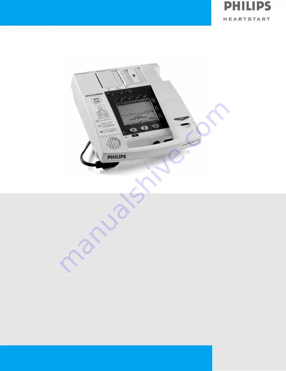
Page 1: ...H E A R T S TA R T X LT S e r v i c e M a n u a l M 3 5 0 0 B M 5 5 0 0 B ...

Page 2: ......

Page 3: ...Service Manual M3500B HeartStart XLT M5500B Heartstart 4000 Defibrillator Monitor ...

Page 4: ... whole or in part is prohibited without the prior written consent of the copy right holder WARNING Radio Frequency RF interference from nearby transmitting devices may seriously degrade performance of the M3500B M5500B defibrillator moni tor Electromagnetic compatibility with surrounding devices should be assessed prior to using the defibrillator CAUTION Use of supplies or accessories other than t...

Page 5: ...escribe conditions or actions that can result in damage to the equipment or loss of data WARNING Warning statements describe conditions or actions that can result in personal injury or loss of life Text represents messages that appear on the display represents softkey labels that appear on the display above or below the button to which they correspond Softkey ...

Page 6: ......

Page 7: ...on Matrix 2 3 Test Equipment 2 8 Configuration and Diagnostic Modes 2 10 Configuration Mode 2 10 Diagnostic Mode 2 11 Performance Verification 2 12 Visual Inspection 2 12 Functional Checks 2 13 ECG Functional Checks 2 13 Shock Advisory Functional Check 2 14 Synchronized Cardioversion Functional Check 2 14 Sp02 Functional Check 2 15 Diagnostic Tests 2 16 The System Log 2 16 Extended Self Test 2 17 ...

Page 8: ...Test the Unit 3 2 Initial Assessment 3 3 Attempt Power Up 3 3 Evaluate the Response 3 3 Diagnosing External Failures 3 4 Capture the Configuration Data 3 4 Print the System Log 3 4 Rule out external components and improper use 3 4 Diagnosing Internal Failures 3 5 Run Self Tests 3 5 Use the Troubleshooting Tables 3 5 Configuration and Diagnostic Modes 3 5 Accessing Configuration Mode 3 5 Accessing ...

Page 9: ...ling for Service Laerdal Heartstart 4000 3 34 United States of America 3 34 International Customers 3 34 Removal and Replacement Overview 4 1 Servicing Notes 4 1 Key Components 4 1 Removal Handling and Replacement 4 1 Flex Circuit Connections 4 1 Flex Circuit Handling 4 2 Internal Connections 4 2 Cable and Assembly Placement 4 2 Instrument Reassembly 4 2 Tool Requirements 4 3 User replaceable Part...

Page 10: ...Replacement 4 18 Data Card Door 4 18 Removal 4 18 Replacement 4 18 Labels 4 19 Label Descriptions 4 19 Case Label Set 4 19 Branding Label Set 4 21 Ambient Light Sensor Label 4 21 Speaker Label Set 4 22 Removing and Replacing Labels 4 22 Removal 4 22 Replacement 4 22 Opening the Sealed Case 4 23 Discharging the Power Supply Capacitors 4 23 Primary Method 4 23 Secondary Method 4 23 Separating the Ca...

Page 11: ...33 Removal 4 33 Replacement 4 33 Control PCA 4 34 Removal 4 34 Replacement 4 35 LCD Display Assembly 4 37 Removal 4 37 Replacement 4 37 SpO2 PCA 4 38 Removal 4 38 Replacement 4 39 ECG Connector 4 40 Removal 4 40 Replacement 4 41 SpO2 Connector 4 42 Removal 4 42 Replacement 4 43 Manual Keypad Assembly 4 44 Removal 4 44 Replacement 4 47 Interface PCA 4 50 Removal 4 50 Replacement 4 52 Speaker 4 55 R...

Page 12: ...500B 4 70 Disposing of the SLA Battery 4 70 Replacement Parts Overview 5 1 Ordering Replacement Parts 5 1 Ordering Supplies and Accessories 5 1 Key Components 5 1 Calling for Service Philips HeartStart XLT 5 2 United States of America 5 2 Latin America 5 2 Canada 5 2 Other International Areas 5 3 Calling for Service Laerdal Heartstart 4000 5 4 United States of America 5 4 International Customers 5...

Page 13: ...ery PCA 6 4 Battery 6 4 Printer 6 4 System Level Interconnections 6 5 System Functional Descriptions 6 6 Signal and Data Flow 6 6 ECG Monitoring Functions 6 7 ECG Pads 6 7 ECG 3 5 lead cable 6 7 Patient impedance functions 6 8 SpO2 Monitoring Functions 6 8 Defibrillation Functions 6 9 Charging 6 9 Delivering a shock 6 9 Delivering synchronized cardioversion 6 10 Pacing Functions 6 11 Audio Functio...

Page 14: ...cy Response 7 4 Patient Isolation 7 4 Display 7 4 Thermal Array Printer 7 4 Continuous Real Time Strip 7 4 Battery and Battery Power Modules 7 5 Noninvasive Pacing 7 6 SpO2 Pulse Oximetry 7 6 Accuracy with 7 6 Event Storage 7 6 Internal Event Summary 7 6 Data Card Event Summary 7 6 General 7 7 Environmental 7 7 Waveforms 150J 7 8 150J 25 ohms 7 8 150J 50 ohms 7 8 Waveforms 150J continued 7 9 150J ...

Page 15: ... Waveforms 200J continued 7 12 Waveforms 200J continued 7 13 Symbol Definitions 7 14 Safety Considerations 7 16 Electromagnetic Compatibility 7 18 Reducing Electromagnetic Interference 7 18 Restrictions for Use 7 18 Immunity Level 7 19 ...

Page 16: ......

Page 17: ...nitor The M3500B M5500B is a biphasic semi automatic external defibrillator This portable lightweight device offers two modes of operation for defibrilla tion z Semi Automatic External Defibrillation AED Mode z Manual Mode In AED Mode the M3500B M5500B analyzes the patient s ECG and advises the clinician whether or not to deliver a shock In Manual Mode the M3500B M5500B turns control of the defibr...

Page 18: ...A or by the DC Power Module M3518A M5518A NOTE The defibrillator will take longer to charge when powered with either power module without a battery installed The recommended practice is to use a bat tery in conjunction with the power module to ensure optimal performance For information on either the power modules or the adapter see the documen tation supplied with the power module or adapter Insta...

Page 19: ... a fac tory authorized repair facility Component level repair is extremely difficult due to the extensive use of surface mount technology and the high parts den sity on the circuit boards Unauthorized component replacement can impair performance of the M3500B M5500B Batteries Power Modules Battery Charger Adapter The repair philosophy for the SLA battery M3516A M5516A AC Power Module M3517A M5517A...

Page 20: ......

Page 21: ... Internal External Repairs No Trouble Found External Repairs are those involving the repair or replacement of one or more of the items below No Trouble Found applies when no malfunction can be found or when the problem appears to be due to improper use In either situation the key point is that the case has not been opened z ECG cable z SpO2 cable or sensor z Battery Test Matrix A list of the tests...

Page 22: ...d when the case has not been opened z Perform the Visual Inspection page 2 12 z Run the Extended Self Test page 2 17 z Print and Verify the System Log page 2 16 Printer If the printer was replaced and the case was not opened the following tests are required z Perform the Visual Inspection page 2 12 z Run the Extended Self Test page 2 17 z Run the Printer Test page 2 21 z Print and Verify the Syste...

Page 23: ... no missing items then Visual Inspection passes Example VI p Functional Checks F In normal Operating Mode perform the following func tional checks If all functions respond as expected Example F p ECG page 2 13 Waveform clear on dis play HR correct on display HR alarm works Leads off pads off indicators as expected Shock Advisory page 2 14 Shock Advised only when appropriate Synchronized Cardiover ...

Page 24: ...n User Interface test passes ECG Tests E In Diagnostic Mode run the ECG Tests page 2 22 If all data within limits all checks pass Example E p Status messages lead pad DSP Good displayed for all three status messages PCI measurement If all PCI measurements are within the following ranges PCI Test Load attached 50 30 Ω PCI Pads open 2000 Ω then ECG test passes Pacing Test P In Diagnostic Mode run th...

Page 25: ...ower DB Using only battery power enter Diagnostic Mode and run the Defibrillator Test at 200Joules page 2 28 If the measurements are as follows Example DB p Displayed by M3500B M5500B Available Energy after Shock 0 Msec to charge 3000 msec Delivered energy Actual delivered energy 200 7 Impedance 42 to 57 Ω Defib errors None 0 then the Defibrillator test Battery Power passes Defibrillator Disarm Te...

Page 26: ...odule is used S3 p aa bb cc dd ee ff ggg hhh iii Example S3 p 9 49 49 10 50 50 100 499 750 ECG Patient Cable If readings are as expected Source Normal Condition aa 10 uA Source Single Fault Condition open earth open neutral bb 50 uA With Mains on applied part Single Fault condition cc 50 uA then Safety Patient Lead Leakage test passes SPO2 If readings are as expected Source Normal Condition dd 10 ...

Page 27: ...000 uA then Safety Pads Test passes Note When recording test results separate results within a test by slashes separate tests by a semicolon and do not use empty spaces For example VI p F p X p U p E p P p DM p DB p D p S1 p 200 300 S3 p 9 49 49 10 50 50 100 499 750 Table 2 1 Performance Verification and Safety Tests Continued Test Group Name Test or Inspection to Perform Expected Test Results Dat...

Page 28: ...ilable from Philips Medical Systems M1781A Table 2 2 Equipment List Equipment Test Specifications ECG Simulator Calibrated Leads ECG simulator Amplitude accuracy 2 Rate accuracy 2 Calibrated Paddles ECG simulator Amplitude accuracy 2 Rate accuracy 2 Defibrillator Analyzer Waveform compatibility Meets all specs below using biphasic truncated exponential waveform Load resistance 50 Ω 1 non inductive...

Page 29: ...uipment 2 Pacer tester Load impedance 400 Ω Current measurement accuracy 10 mA 50 mA 2 mA 50 mA 200 mA 4 Rate measurement accuracy 30 180 ppm 0 5 Waveform duration accuracy 30 180 ppm 1ms Table 2 2 Equipment List Equipment Test Specifications ...

Page 30: ...physically separate from cards used by the clini cal staff for data storage 3 Enter Configuration Mode Press softkeys 4 and 5 at the same time and hold them down while turn ing the power on See Figure 2 1 for softkey numbering 4 Select and manage Configuration choices z To select a configuration press the and softkeys to move up or down the list until the desired Settings item is highlighted Then ...

Page 31: ...r off Make sure the power is off 2 Enter Diagnostic Mode Press softkeys 4 and 6 at the same time and hold them down while turn ing the power on See Figure 2 1 3 Wait for the Diagnostic software to initialize This will take several seconds The unit is ready to proceed when the screen cursor responds to softkey inputs 4 Select the desired test or function z To select a test press the and softkeys to...

Page 32: ...Check inside the printer bucket and clean out any accumulation using gloves and an approved cleaner z Residue on the thermal printhead z Printer roller wear z Wear or damage to power cord and associated strain relief z Corrosion on connector pins printer parts or battery contacts Pass Only normal wear no damage serious enough to inhibit performance No corrosion visible 2 Check ECG electrodes and d...

Page 33: ... 5 lead ECG cable Set the simulator for normal sinus rhythm NSR 1mV amplitude at some nominal rate e g 60 bpm 2 Set the M3500B M5500B to Manual operating mode not Diagnostic Mode 3 Using the softkey verify that the display shows a normal ECG with a clean baseline for both Pads and Lead II 4 Verify the Heart Rate HR displayed is correct 5 Disconnect the ECG simulator from the pads cable and verify ...

Page 34: ...red energy into the test load If it does not or you are not sure wait until the defibril lator reports Shock cancelled before proceeding with other tests Synchronized Cardioversion Functional Check This section describes how to check the operation of the synchronized cardio version function 1 Connect the ECG simulator to the ECG cable Connect the defibrillator analyzer to the pads cable 2 Set the ...

Page 35: ... performed if SpO2 is installed 1 Attach the SpO2 transducer to your finger 2 Activate Manual Mode and press the SpO2 softkey to turn SpO2 on 3 The SpO2 value displayed should be in the range of 95 100 If the value is less than 95 check that your finger is fully inserted into the sensor and properly positioned ...

Page 36: ...rial number on the bottom of the case If the printout is not correct investigate and resolve the source of the mismatch Then reset the hard ware options and serial number as needed using the Support Software Tool See The Language Support Tool on page 4 67 5 If there are errors reported in the System Log a Check the time and date stamps to see if they are recent errors or not Consult Table 3 2 Erro...

Page 37: ...can generate an erroneous Not Tested or Fail message 1 Connect the test load to the pads cable 2 Access the Diagnostic Test menu as described in Diagnostic Mode above 3 Select Extended Self Test and press The printout should appear similar to Figure 2 3 Figure 2 3 Sample Extended Self Test Printout 4 Check the printout to verify that the time and date are correct If they are not reset them using t...

Page 38: ... clock or the Biphasic clock z DEFIB The Defib test charges the defibrillator capacitor and then disarms it It does not deliver the energy outside the unit The pads cable and test load must be connected for the test to run otherwise the test result will be Not Tested z FE The Front End FE test checks that the main processor is communicating with the Digital Signal Processor DSP and that the DSP is...

Page 39: ...ntrols Test and press The screen will display a map of the front panel keys 3 Press each of the numbered softkeys in turn See Figure 2 1 on page 2 11 for numbering of softkeys Each softkey number on the display should be highlighted each time that key is pressed Don t press Softkey 4 at this time This will return you to the Main diagnostic mode menu 4 Check each of the Contrast ECG Size and Volume...

Page 40: ... light in turn To check the audio output 1 Select Audio Test and press 2 The screen will display Audio Test menu Press the and softkeys to move up or down the list to select the desired test Then press to begin that test Check the Shutdown Warning and the Voice Prompt the other responses are for reference The results should be as described below Press to end the test and return to the main audio t...

Page 41: ... lines 3 The area of Figure 2 4 labeled C contains printouts of all characters and symbols Verify that they are readable 4 Measure between the long tick marks B in Figure 2 4 to verify paper speed Distance should be 25mm 5 1 25 mm 5 Open the printer door and press the key The unit should sound a series of 3 tones indicating a printer problem 6 Take out the paper close the door and press the key Th...

Page 42: ...t menu as described in Diagnostic Mode on page 2 11 2 Select ECG Test and press 3 The display should look similar to Figure 2 5 Figure 2 5 ECG Test Display Checking settings In areas with 50 Hz power the AC Line Filter should be set to 50 Hz If the set ting is incorrect access the Configuration Mode and correct it See Configu ration Mode on page 2 10 The PCI setting should always be Off factory se...

Page 43: ...ween the Leads Front End FE and the Digital Signal Processor DSP z The Pads FE test checks that communication is working between the Pads FE and the DSP z The DSP test checks that communication is working between the DSP and the rest of the monitor DC Offset This test is for manufacturer s use only and should be ignored ECG amplifier tests These tests measure both the gain and the noise of the two...

Page 44: ...as cc If the unit exhibits more than 30 uV of noise try repositioning the cable or unit to minimize external interference See Reducing Electromagnetic Interference on page 7 18 Also try various combinations of having the ECG simulator turned on or off and if applicable whether the simulator is plugged into the AC mains 4 Following the instructions under Changing settings set Selected lead to Pads ...

Page 45: ... 2 From the Diagnostic Menu select Pacer Test and press The dis play should look similar to Figure 2 6 Figure 2 6 Pacer Test Display 3 Press The LED to the left of the button will illuminate The screen display of Pacer Status will change to Stopped 4 Press Pacer Status will change to Pacing and pacing will begin at the default settings of 70 beats per minute bpm and 30 mA 5 The Pacer should be del...

Page 46: ...tton increase the output to 200 mA 9 The Pacer should be delivering a current of 200mA 20mA Record the delivered current indicated by the Pacer tester as bbb 10 The display on the M3500B M5500B should read the delivered current as measured by the Pacer tester bb 20 mA 11 Turn off Pacing by pressing the button Rate Output Pacer ...

Page 47: ... the defibrillator analyzer to the pads cable Set the analyzer to measure delivered energy If needed reset the analyzer s display to read 0 3 Turn the defibrillator on and from the Diagnostic Menu Select the Defib Meas Test and press 4 Use the softkey to select 200J Then press the softkey to charge the defibrillator Press Readings from defibrillator analyzer Read the delivered energy indicated by ...

Page 48: ... Turn the defibrillator on and from the Diagnostic Menu Select the Defib Meas Test and press 4 Use the softkey to select 200J Then press the softkey to charge the defibrillator Press Readings from defibrillator analyzer Read the delivered energy indicated by the defibrillator analyzer It should be 200J 15 30J Record as aaa Readings from M3500B M5500B display The results displayed by the M3500B M55...

Page 49: ...nalyzer s display to read 0 2 From the Diagnostic Menu Select the Defib Meas Test and press 3 Use the softkey to select 200J Then press the softkey to charge the defibrillator Press Readings from defibrillator analyzer Read the delivered energy indicated by the defibrillator analyzer It should be 0J or be blank Readings from M3500B M5500B display The results displayed by the M3500B M5500B should b...

Page 50: ...he AC Mains line volt age used in the customer s facility there is no need to test both 120VAC and 240VAC Also test both Normal and Reverse Polarity line connections and record the worst case value Earth Leakage z Normal Condition 500 uA 300 uA for UL Record as aaa z Single Fault Condition 1000 uA Record as bbbb Patient Lead Leakage Test both Leads C and pads B inputs z Source Normal Condition 10 ...

Page 51: ...rt the test 5 Allow the test to proceed to completion The test takes approximately three hours and is complete when test results print out and the device turns itself off 6 Review the test results and take the appropriate action as follows Table 2 3 Battery Capacity Test Results NOTE If the message Unsupported Battery appears replace the battery with the M3516A battery See Table 3 15 on page 3 29 ...

Page 52: ......

Page 53: ...r the Control PCA and selected connectors and other items Repairs that involve replacing components on a PCA are not supported CAUTION Individual component replacement should not be attempted outside of a fac tory authorized repair facility Component level repair is extremely difficult due to the extensive use of surface mount technology and the high parts den sity on the circuit boards Unauthoriz...

Page 54: ...page 3 4 to identify problems that can be resolved without further troubleshooting Finally if needed use Diagnosing Internal Failures on page 3 5 to isolate the problem to a particular subassembly If no trouble is found proceed to the Performance Verification and Safety Tests chapter for instructions on tests to run Perform the Repair Follow the procedures in the Removal and Replacement chapter to...

Page 55: ...o response IF The unit emits no sounds and no changes are visible on the display THEN Troubleshoot further using Table 3 1 on page 3 9 Unit Unresponsive Minimal response IF Unit provides only a slight response such as a click or chirp from the speaker or a change in the contrast or the borders of the display THEN Replace the Control PCA see Removal and Replacement on page 4 1 Return to this sectio...

Page 56: ... Supplies and Accessories make sure the unit has z An undamaged fully charged M3516A M5516A battery z A new dry roll of Philips 40457C D printer paper Printer paper may jam if paper is wet Also printer may be damaged if wet paper is allowed to dry while in contact with printer elements z Cables and sensors which are approved by Philips and known to be good Also make sure that all external cables a...

Page 57: ...uration and Diagnostic Modes Some of the Troubleshooting procedures look for responses from the unit that are dependent on that unit s configuration Similarly many procedures require that the unit be in Diagnostic Mode Follow the instructions given below to enter these modes Accessing Configuration Mode These instructions describe briefly how to enter Configuration Mode See the Instructions for Us...

Page 58: ...ng the Extended Self Test and other Diagnostic Tests For details of running these tests see Diagnostic Tests on page 2 16 1 Make sure the power is off 2 Press softkeys 4 and 6 at the same time and hold them down while turn ing the power on See Figure 3 1 for softkey numbering 3 Wait for the Diagnostic software to initialize This will take several seconds The unit is ready to proceed when the scree...

Page 59: ...ort Software Tool See The Language Support Tool on page 4 67 5 If there are errors reported in the System Log a Check the time and date stamps to see if they are recent errors or not Consult Table 3 2 Error Codes on page 3 11 to identify the errors Then begin troubleshooting as needed see the Troubleshooting chapter b Check that the time and date are correct If they are not correct access Configur...

Page 60: ... any parts check to see if the cables and flex circuits are properly connected See Servicing Notes on page 4 1 Table 3 1 Unit Unresponsive Table 3 2 Error Codes Table 3 3 System Messages Table 3 4 Momentary Messages Table 3 5 Audio Tones Table 3 6 Extended Self Test Failures Table 3 7 Operational Problems ECG Monitoring Pads or Leads Table 3 8 Operational Problems SpO2 Monitoring Table 3 9 Operati...

Page 61: ...on page 3 30 Power indicator turns RED Power Source volt age low Check correct source volt age Failure in Power Module Replace Power Module Power indicator turns GREEN Proceed to step 2 2 Connect Power Module to unit Power indicator turns RED Short in unit s 12 volt wiring 1 Check replace Battery PCA 2 Check replace wiring to Power PCA Short on Power PCA Replace Power PCA Short on Control PCA Repl...

Page 62: ...d dis play from Control PCA at Control PCA Then pro ceed to step 5 5 Attempt to power up unit Unit powers up to some working state Short in printer or dis play Isolate the fault by recon necting one at a time and powering up again Then replace the display or printer as needed Unit still unresponsive Short or other failure somewhere in unit 1 Replace Control PCA 2 Replace Power PCA 3 Replace Interf...

Page 63: ...re 1 Replace Interface PCA 2 Replace Control PCA 04000 Pacer failure Replace Power PCA 08000 Processor error Replace Control PCA 10000 1FFFF System monitor failure 1 Cycle power 2 Replace Control PCA 10001 Processor Synchronization Error Cycle power 10004 Synchronization Time Out Cycle power If error does not repeat run ALL Performance Verification Tests If unit passes all tests the unit can be re...

Page 64: ...gain making sure not to touch the unit during the test 2 Replace Power PCA 3 Replace Control PCA 90009 Self Test failure Front End 1 Replace Power PCA 2 Replace Control PCA 3 Replace Interface PCA 9000A Lithium backup battery failure 1 Replace lithium battery 2 Replace Control PCA A0000 A7FFF Data Card failure 1 Replace Data Card 2 Replace Control PCA A8000 AFFFF Data Archival error 1 Replace Data...

Page 65: ...en insert a new empty M3510A M5510A Data Card and turn the device on ECG Fault The ECG data acquisition system failed and data is unavailable from the 3 or 5 lead monitoring electrodes Service the unit See Troubleshooting on page 3 1 and Table 3 7 on page 3 19 Monitor Failure Cycle Power An error has occurred in the monitoring subsystem Turn power off then on If message reap pears service the unit...

Page 66: ... Ser vice Unit A serious malfunction has occurred Service the unit See Troubleshooting on page 3 1 SpO2 Cable Off The SpO2 cable is not connected to the device Attach the SpO2 cable to the M3500B M5500B SpO2 Light Interf The level of ambient light is so high that the sensor cannot obtain an SpO2 read ing or the sensor or cable is damaged 1 Cover the sensor with an opaque mate rial 2 Check the sens...

Page 67: ...al interference SpO2 Sensor Fail The SpO2 cable is not connected to the device or the cable or sensor are broken 1 Attach the cable to the M3500B M5500B 2 Replace cable and or sensor System Failure Cycle Power A serious error has occurred Turn power off then on If message reap pears service unit See Troubleshoot ing on page 3 1 Service Unit Appears during the Shift System Check 1 Replace Data Card...

Page 68: ... defibrillator being charged To deliver a shock press within 30 seconds of the defibrillator being charged is pressed None No Shock Delivered Patient impedance is too high or too low 1 Make sure pads are applied properly 2 Replace the pads 3 Replace the pads cable Check Printer Printer paper is absent or jammed the printer door is not closed properly 1 Reload printer paper 2 Make sure the door is ...

Page 69: ...y Messages Continued Message Possible Cause Corrective Action Sync Pace Mode Table 3 5 Audio Tones Tone Meaning Suggested Action At power on a low tone of approx 1 second followed by a series of higher pitched short tones Normal power on sequence None needed At power on a continuous beep of about 7 seconds System failure processors not communicating Turn power off then on If problem reoccurs repla...

Page 70: ...stem FAIL 10 Lithium backup battery failure Replace lithium battery Data Card Data Card full or incompatible or defective Replace Data Card with new empty M3510A M5510A Failure on Control PCA Replace Control PCA Pacer Defib Failure on Power PCA Replace Power PCA Failure on Control PCA Replace Control PCA FE Failure on Control PCA Replace Control PCA Failure on Power PCA Replace Power PCA Failure o...

Page 71: ...PCA Failure in signal processing circuits Replace Control PCA Noisy trace intermittent bursts of noise or random spikes Nearby source of time varying inter ference such as radio transmitter paging walkie talkies or X Ray system Try moving cable leads try relocat ing unit Failure in ECG front end Pads Replace Power PCA Leads Replace Interface PCA Failure in signal processing circuits Replace Contro...

Page 72: ...le Defective Power PCA Replace Power PCA Trace distorted Failure in ECG front end Pads Replace Power PCA Leads Replace Interface PCA Failure in signal processing circuits Replace Control PCA One or more ECG controls don t respond e g select lead or ECG size Failure in keypress detection pro cessing 1 Replace Control PCA 2 Replace Interface PCA Failure in keys connections Replace Top Case Assembly ...

Page 73: ...just the volume The amplitude of the QRS complex is too small to detect Adjust the size of the ECG Fails ECG Test in Diagnostic Mode Failure in Pads ECG front end or signal processing 1 Replace Power PCA 2 Replace Control PCA Failure in Leads ECG front end or signal processing 1 Replace Control PCA 2 Replace Interface PCA Table 3 7 Operational Problems ECG Monitoring Pads or Leads Continued Sympto...

Page 74: ... Detects both OK Go to step 3 Either Pads Off or Cable Off fail replace 1 Pads connector 2 Power PCA 3 In Diagnostic Mode run Controls Test and test CHARGE key Key tests OK Replace Control PCA Key not OK Replace 1 Inter face PCA 2 Top Case Assem bly 3 Control PCA Won t charge in AED Mode Pads connector or internal wir ing failure Power PCA failure Control PCA failure Interface PCA failure CHARGE k...

Page 75: ... 2 DISARM key failure intermittent Replace pads pads cable Diagnose further as follows In Diagnostic Mode run Controls Test and test DISARM key Key tests OK Replace 1 Power PCA 2 Control PCA Key not OK Replace 1 Inter face PCA 2 Top Case Assembly3 Control PCA Charges slowly about 4 5 sec instead of 2 3 sec Battery too old or not fully charged Replace with new fully charged bat tery Also run Batter...

Page 76: ...roblems Defibrillation and Synchronized Cardioversion Continued Message or Symptom Possible Causes Suggested solution Table 3 10 Operational Problems Pacing Message or Symptom Possible Causes Suggested solution Doesn t deliver correct current into Pacer Tester or delivers no current at all Control PCA failure Replace Control PCA Power PCA failure Replace Power PCA Doesn t measure its own delivered...

Page 77: ...d Check door latch Dirty printhead Clean printhead Printer failure Replace printer Control PCA failure Replace Control PCA Paper moves but print quality poor or some dots missing Dirty printhead Clean printhead See Cleaning the Printer Printhead on page 4 9 Printer failure Replace printer Loud buzzing or grinding noise Door improperly latched Check door latch Waveforms or text distorted even thoug...

Page 78: ...e Ambient light sensor failure Diagnose as follows In Diagnostic Mode run Display Test and press BACKLIGHT ON and BACKLIGHT OFF softkeys Backlight does not respond Replace 1 Display 2 Control PCA Backlight responds normally test Ambient Light Sensor below In Diagnostic Mode run Display Test and check ambient light read ings Normal Replace 1 Display 2 Control PCA Abnormal or not responding Replace ...

Page 79: ...ompts Symptom Possible Causes Suggested solution No audio at all Speaker failure Replace Speaker Assembly Control PCA failure Replace Control PCA Audio is distorted Damage to speaker label Replace speaker label Speaker failure Replace Speaker Assembly Control PCA failure Replace Control PCA Buzzing noise when audio active Damage to speaker label Replace speaker label Debris between speaker and spe...

Page 80: ...PCA failure Diagnose as follows In Diagnostic Mode run Controls test and identify all unresponsive keys Some keys don t respond Replace 1 Control PCA 2 Interface PCA 3 Top Case Assembly All keys don t respond Replace 1 Control PCA 2 Interface PCA One or more of the other keys don t respond display controls printer controls manual pacing Key failure Interface PCA failure Control PCA failure Diagnos...

Page 81: ...lure on Control PCA Power PCA or Battery PCA Replace 1 Control PCA 2 Power PCA 3 Battery PCA Charging indicator doesn t come on when Power Module plugged into Battery Charger Adapter or into M3500B M5500B Power module failure Replace Power Module Fails Battery Capacity Test Battery old worn out or failed Replace battery Failure on Control PCA Replace Control PCA Done indicator doesn t come on even...

Page 82: ...ted to Mains AC DC Con nected M3500B M5500B Battery in Place Unit Power ON R RED G GREEN OR ORANGE AMBER Y YES N NO don t care OFF OFF OFF N Normal G OFF OFF Y Normal G OFF OFF Y Y N Normal G OR OFF Y Y Y Battery is charging G G OFF Y Y Y Battery 90 charged G G G Y Y Y Battery fully charged R OFF OFF Y Y If Power light was green before connecting to unit fault in M3500B M5500B R OFF OFF Y N Mains ...

Page 83: ...ly recognized during power up sequence Turn power off for 2 minutes then on again Card is full or not a supported type Use a new empty M3510A M5510A Data Card Data on the card corrupted The card was removed while the unit power on Only remove card after power is turned off Delete corrupted files using the Event Review Data Man agement System Fails Data Card Test in Diagnostic Mode Card is full or ...

Page 84: ...For telephone assistance call the Philips Medical Systems Response Center nearest to you or visit our website at www medical philips com cms United States of America Latin America Canada Medical Response Center Tel 800 548 8833 Medical Response Center Tel 954 835 2600 Medical Response Center Tel 800 323 2280 ...

Page 85: ...87 Netherlands United Kingdom Tel 31 20 547 2555 Fax 31 29 547 2949 Tel 00 44 7002 432584 Belgium for Dutch Belgium for French Tel 32 2 525 7102 Fax 32 2 525 71 91 Tel 32 2 525 710 3 Fax 32 2 525 71 91 Spain Poland Tel 34 902 30 40 50 Fax 34 91 326 39 66 Tel 48 22 5710499 Austria Finland Tel 43 1 60101 820 Tel 09 6158 0400 Switzerland Russia Tel 0800 80 10 23 Tel 7 095 933 0339 Fax 7 095 933 0338 ...

Page 86: ...e assistance call the Laerdal office nearest to you or visit our website at www medical philips com cms United States of America International Customers Laerdal Medical Corporation Tel 800 547 4781 Australia United Kingdom Tel 61 3 95694055 Tel 44 1689 876634 Norway Other International Areas Tel 946 71 700 Tel 47 51511700 ...

Page 87: ... its serial number This data must be recorded for both the failed assembly and the replacement assembly Philips Medical Systems service personnel must record this information on the Customer Service Order CSO The Key Components that are part of the replacement assemblies are listed in Table 5 15 on page 5 20 Removal Handling and Replacement The following sections give details of how to successful ...

Page 88: ...acement How the wires and cables are routed and dressed inside the chassis plays an important role in two areas in preventing long term wear problems and in reducing electromagnetic and radio frequency interference emitted by the defibrillator z When you disassemble any part of the defibrillator pay special atten tion to how cables and wires are routed z When you reassemble the defibrillator be su...

Page 89: ...h down to recessed case screws z Phillips 1 screwdriver z Small straight bladed screwdriver z Straight tip needle nose pliers or tweezers z Bent tip needle nose pliers whose jaws are covered with a soft mate rial such as plastic tubing or tape z Fine nose wire cutters z Utility knife z High voltage discharge tool for discharging the defibrillator capacitor Philips part number M2475 69572 z Clip le...

Page 90: ...oor surfaces with isopropyl alcohol Allow them to dry b Lay the door on a clean flat surface with its underside facing up the side that is concealed when the door is closed c The new door will come with labels both for units with Pacing and without Pacing Select the correct label for your unit d Peel the new Manual Operation label off the backing material e Starting with the top edge align the lab...

Page 91: ...0B M5500B Service Manual 4 5 User replaceable Parts and Accessories 4 3 Push as shown in Figure 4 2 until the door snaps into place Figure 4 1 Aligning the Manual Door Figure 4 2 Snapping the Door in Place ...

Page 92: ...User replaceable Parts and Accessories 4 6 Removal and Replacement Figure 4 3 Attaching the Door Labels Label Top label ...

Page 93: ...eps 1 through 7 as shown in Figure 4 4 Note the screws are Phillips head not Torx Also after loosening the captive screws step 6 lay the unit flat and lift the defibrillator up off the mounting plates to disengage it from the 2 locating pins in the carrying case Then slide it out of the carrying case as shown in step 7 Figure 4 4 Removing the Carrying Case ...

Page 94: ...ll the carrying case on the M3500B M5500B follow steps 1 through 7 as shown in Figure 4 5 Slide the unit into the case as shown in step 1 then lower it onto the 2 locating pins in the case before tightening the screws in step 2 Figure 4 5 Installing the Carrying Case Printer ribbon cable ...

Page 95: ...inthead are duplicated here Instructions on running the Battery Capacity Test are duplicated on page 2 31 Cleaning the Printer Printhead If the printout has light or varying density printing clean the printhead to remove any buildup of paper residue To clean the printhead 1 Slide the printer door to the right until the paper roller pops up 2 Pull up on the plastic removal tab to remove the roll of...

Page 96: ...ealed case Not all the assemblies described here are available as replacement parts see the Replacement Parts chapter CAUTION Be sure to work in a static safe environment The work surface and area sur rounding it must be static free Use a static control wrist band in conjunction with an antistatic pad which is grounded per the manufacturer s instructions ...

Page 97: ...Open the door over the paper by moving the sliding door in the direction of the arrow and lifting up the platen and roller 4 Loosen the 2 T10 screws now visible on the top and bottom edges of the printer assembly at the left end See Figure 4 6 5 Peel up the label with the arrow on it 6 Loosen the 2 T10 screws under the label 7 Pull the printer assembly and its screws straight upward 8 Unlatch the ...

Page 98: ...on the new printer Leave the paper door open until the screws under the label are tightened 3 Put the 4 screws in the holes in the new printer Get the 2 screws back in the holes under the label with tweezers or fine nose pliers 4 Reconnect the ribbon cable Be sure to engage the 2 latches on the ends of the ribbon connector 5 Lower the printer straight down into the instrument 6 Tighten all screws ...

Page 99: ... of the door out away from the side of the printer frame to unsnap the door from the printer Replacement a Starting at the end of the rails furthest out from the printer hook the retaining clips on one side of the door over the rail and snap the clips on the other side of the door into place This is made easier by pulling out on the retaining clips to spread them further apart and by squeez ing th...

Page 100: ...a slot in the printer frame c Grasp the body of the printer just below the hinge pins and squeeze the body so that the hinge pins move in Disengage one pin first then the other d Lift the platen assembly from the hinges Keep track of the springs Replacement a Reinstall the springs on their correct hinge pins b Grasp the body of the printer just below the hinge pins and squeeze the body so that the...

Page 101: ...m its carrying case 2 Remove the battery 3 Turn the unit upside down with the handle facing you The battery cover is at left side of the bottom surface Note that Figure 4 8 shows the case standing up for clarity 4 Remove the 7 screws as shown in Figure 4 8 The screws are size coded only remove the T10 size 5 Lift battery cover up Figure 4 8 Removing the Battery Cover Battery cover Bottom case ...

Page 102: ...Carefully insert a battery in the battery compartment Be sure the battery stays flat and does not push up out of position 3 While keeping the battery in place replace the battery cover starting with the end by the battery PCA See Figure 4 9 which shows the case stand ing upright for clarity Insert the tab on the cover into the mating slot next to the battery spring Then lower the cover into positi...

Page 103: ... 2 Push the Battery PCA back into position being sure the lower edge of the PCA engages the slot in the bottom case 3 Replace the battery cover as described under Battery Cover on page 4 15 Battery Eject Assembly The Battery Latch engages when the battery is fully inserted in the battery compartment and it is released by pushing the Battery Eject Button Removal 1 Remove the battery cover as descri...

Page 104: ...t Check to be sure the Eject Button and Eject Catch slide freely and operate correctly 4 Replace the battery cover as described under Battery Cover on page 4 15 Data Card Door Removal 1 Open the door This will expose the shaft on which the door pivots Note the spring wrapped around the shaft 2 Using a small flat bladed screwdriver catch the right end of the pivot shaft and slide it toward the cent...

Page 105: ...y Label Descriptions The following sections describe each of the label sets in more detail Case Label Set The case label set includes most of the labels on the top and bottom case except those that vary with the brand under which the product is sold Philips or Laerdal and those that vary with product options pacing SpO2 This set includes z AED Operation label z Printer key label z OFF ON label z D...

Page 106: ...Locations AED Label Danger Warning IPX4 Label Printer Key Label Blank Yellow Label OFF ON label Printer Latch Label Patient Connector Label next to patient connector Eject Data Card label next to card slot Power Connector Label next to connector ECG SpO2 label ...

Page 107: ... Heartstart 4000 outside of North America M3500 69558 These do not have language localization Ambient Light Sensor Label The Ambient Light Sensor allows the Display to automatically turn the back light on and off depending on ambient light levels The light sensor label cover seals the opening in the case through which light reaches the sensor The cover is formed of a small clear circular area surr...

Page 108: ...label and peel the entire label off the case Be careful not to gouge the case Replacement 1 Clean off all adhesive residue from the case by rubbing the dry surface with your finger and rolling up the adhesive residue Solvents are inef fective as is scraping with a tool 2 Clean the surface with isopropyl alcohol Allow it to dry 3 Peel the new label off the backing material 4 Starting with one strai...

Page 109: ...he power supply capacitors are now discharged 3 If you do not hear a click use the Secondary Method Secondary Method 1 Open the case as described under Separating the Case on page 4 25 2 Discharge the defibrillator capacitor as described under Discharging the Defibrillator Capacitor on page 4 27 3 Disconnect and remove the defibrillator capacitor as described in Defibrillator Capacitor on page 4 6...

Page 110: ...Opening the Sealed Case 4 24 Removal and Replacement Figure 4 13 Battery Connector Location 4 Pin Battery Connector ...

Page 111: ...emove the Data Card by pushing its Eject button and pulling the card out Be sure the button is fully in if it is left partially extended it can catch on the bottom case and break off 2 Turn the unit upside down display facing down with the handle closest to you 3 Remove the Battery Cover to gain access to the case screw inside the bat tery compartment See Battery Cover on page 4 15 4 Remove 6 T15 ...

Page 112: ... slightly c Then pull up the front of the top case d While pulling up slide the top case away from you toward the back of the unit to avoid catching the Data Card Eject button on the bot tom case 8 Once the case halves are separated pivot the top case to the right so it turns upside down Lay the top case on the work surface upside down and next to the bottom case section See Figure 4 15 9 The two ...

Page 113: ...hat both foam pieces are contoured to fit in the case only one way 2 Inspect the Disarm Pathway located under the Defibrillator Capacitor on the left side of the Power PCA The Disarm Pathway consists of 2 large power resistors Disarm Resistors a red inductor and the PCA traces that connect them See Figure 4 16 on page 4 28 Look for signs of arc ing or burning damage to the resistors or inductor bl...

Page 114: ...ower PCA where the Defibrillator Capacitor is connected Maintain this connection for at least 5 seconds c Repeat steps a and b using the other Disarm Resistor The defibrilla tor capacitor is now discharged even if one of the resistors is dam aged Figure 4 16 Discharging the Defibrillator Capacitor High Voltage Discharge Tool Touch here first Then touch here Capacitor cover Inductor Disarm resistor...

Page 115: ...ntrol PCA Interface PCA under Control Stack Display cables backlight data thermistor Display on back of Control Stack SpO2 connector Printer connector Speaker connector IRDAbreak off PCA Data card receptacle Power PCA Defibrillator capacitor inside foam shell Battery connector Pads connector Battery PCA cable Printer bucket Printer on other side of case Printer cable ECG connector BOTTOM CASE TOP ...

Page 116: ...ble tie wrap that holds the battery in place Remove the battery from the holder See Figure 4 19 Cleaning a Thouroughly clean the contact clips and new battery terminals with a ProGold wipe Replacement CAUTION Be sure to install the new battery with the correct orientation Follow the polarity markings on the bottom of battery holder under the battery 1 Install the new Lithium battery Secure it in p...

Page 117: ...e Display Also referring to Figure 4 18 on page 4 32 disconnect the 3 cables that con nect the Control PCA to the Display 1 Disconnect the flex circuit on the right side of the Control PCA the Dis play Data Cable Pull out the latches on the ends of connector to release it before pulling on the flex 2 Disconnect the white connector next to it the display thermistor cable This connector has a tiny l...

Page 118: ... ribbon cables 1 from the Power PCA 1 from the Interface PCA Be sure to replace the 2 metal bails on the 2 large ribbon connectors If the clips have become loose or are missing replace them Figure 4 18 Control PCA Connections Printer Cable Power PCA Cable Interface PCA Cable Metal Bails Speaker Cable Display Backlight Cable Display Ther mistor Cable Display Data Cable ...

Page 119: ... around the edge of the metal shield plate and remove the Control Stack See Figure 4 19 Lift it straight up out of the case and lay it down display side up on a soft static protected surface CAUTION Removing the Control Stack exposes the back side of the Display Window Do not touch this side of the Display Window fingerprints etc are very dif ficult to remove from its specially coated surface Repl...

Page 120: ...complete 2 Disconnect the Control PCA from the rest of the unit and from the display as described in Disconnecting the Control PCA on page 4 31 3 Remove the 8 screws around edges of the Control PCA not the screws in the metal shield See Figure 4 20 on page 4 35 4 Remove the 1 screw near the center of the PCA Be careful not to damage any nearby components or traces See Figure 4 20 on page 4 35 5 Sl...

Page 121: ...it Secure it in place with the cable tie wrap 4 Wrap the tie wrap around the battery and secure it to the battery holder 5 Reconnect the Control PCA to the Display and to the rest of the unit see Reconnecting the Control PCA on page 4 31 The order of making con nections does not matter Be sure to replace the 2 metal bails on the 2 large ribbon connectors If the clips have become loose or are missi...

Page 122: ...oval and Replacement 7 Reload the customer s configuration or reconfigure via configuration menus as needed 8 Perform Performance Verification Testing as described in Performance Verification and Safety Tests starting on page 2 1 ...

Page 123: ... See Control Stack on page 4 33 2 Remove the 4 screws from the Display Lift it off the shield plate care fully sliding the flex ribbon out through its slot in the shield plate as shown in Figure 4 21 Figure 4 21 Removing the Display Replacement 1 Connect the flex circuit that came with the new display to the new dis play 2 Slide the flex ribbon in through its slot in the shield plate and up to the...

Page 124: ...orientation and placement of the flex circuit from the SpO2 PCA to the Interface PCA Disconnect this flex circuit at both ends These con nectors have a sliding bar latch slide out toward the edge of the PCA to release then pull out the flex 4 Remove the SpO2 PCA and discard the flex circuit to the Interface PCA Figure 4 22 Removing the Screws SpO2 PCA ECG Connector SpO2 Connector Interface PCA Int...

Page 125: ...e Interface PCA Note the correct orientation as shown in Figure 4 22 the short tail connects to the Inter face PCA and the long tail connects to the SpO2 PCA 4 Attach the adhesive patch onto the bottom of the ferrite 5 Connect the other end of the flex circuit to the SpO2 PCA 6 Replace the SpO2 connector and connect it to the SpO2 PCA See SpO2 Connector on page 4 42 7 Using the adhesive patch secu...

Page 126: ...nectors and pull the shield straight up 3 Referring to Figure 4 22 disconnect the cable from the ECG connector to the Interface PCA at the Interface PCA Press the latch on top of the con nector and pull straight out Swing the cable up out of way and lift it off the case post 4 Release the locking tabs on the metal clip around the ECG connector using a small flat bladed screwdriver Pull up and remo...

Page 127: ... plastic lugs on the connector being sure it locks into place Use the new retainer clip that came with the con nector 4 Loop the cable around the case post and secure with the cable tie pro vided 5 Connect the ECG connector to the Interface PCA being sure the ECG cable is above the SpO2 flex circuit 6 Replace the plastic insulating shield over the SpO2 and Interface PCAs Align the hole in its wide...

Page 128: ...e the underside visible as shown in Figure 4 23 4 Note the orientation and placement of the flex circuit between the SpO2 connector and the SpO2 PCA Disconnect it at the SpO2 PCA There is no latch just pull it straight out 5 Leave the flex circuit from the SpO2 PCA to the Interface PCA con nected 6 Release the locking tabs on the metal clip around the SpO2 connector using a small flat bladed screw...

Page 129: ...9 4 Pivot the PCA down into position Install the 2 T10 screws see Figure 4 23 5 Align the connector and gasket with the notches in case and insert them in the hole Make sure the gasket is in place properly between the connector and the outside of the case 6 Press in firmly on the connector to compress the gasket Slide the metal retainer clip into place behind the 2 plastic lugs on the connector be...

Page 130: ...ex circuits on page 4 1 Removal 1 Disconnect and remove the Control Stack See Control Stack on page 4 33 2 Remove the plastic insulating shield over the SpO2 and Interface PCAs Remove the tape that secures the shield to the metal clips around the SpO2 and ECG connectors and pull the shield straight up 3 Referring to Figure 4 26 disconnect the 2 flex circuits from the Manual keypad to the Interface...

Page 131: ...Manual Door on page 4 4 6 Remove the rubber overlay and the membrane switches as follows a Using a sharp tool such as a utility knife carefully pick up one corner of the rubber overlay and peel the entire overlay off the case Be careful not to gouge the case See Figure 4 27 Figure 4 27 Removing the Rubber Overlay Manual Door Rubber Overlay Door Rails Membrane Switches ...

Page 132: ... case Be careful not to gouge the case The membrane switches will likely peel apart into several layers be sure to remove all layers e Slide the 2 flex circuit tails out of the slot in the case 7 Turn the top case over and loosen the Interface PCA do not remove it as follows a Remove 1 T10 screw from the Interface PCA near the ECG and SpO2 connections See Figure 4 26 on page 4 44 b Release the ret...

Page 133: ...etely 2 Install the new membrane switches as follows a Feed the 2 flex circuits down through the slot in the case as shown in Figure 4 28 Slide the smaller one in first then the larger one Feed them around the side of the Interface PCA nearest their connectors b Peel the backing material off the new switches Handle very carefully and touch the adhesive as little as possible c Starting with the top...

Page 134: ...s on the ECG and SpO2 connectors Secure the shield to the clips with the original tape or use other plastic electrical tape b Replace and reconnect the Control Stack See Control Stack on page 4 33 c Restore any other connections including replacing the defibrillator capacitor and plugging the battery connector back onto the Power PCA if needed 6 Check the membrane switches as follows a Close the c...

Page 135: ...c Starting with the top edge align the overlay exactly and roll it down slowly into place d Press firmly all over especially the edges to adhere the new overlay into place 8 Replace the Manual Door 9 Be sure to specifically check the operation of each of the keys during Per formance Verification by performing a Controls Test see To check the Controls keys on page 2 19 ...

Page 136: ...f flex circuits on page 4 1 Removal 1 Disconnect and remove the Control Stack See Control Stack on page 4 33 2 Remove the plastic insulating shield over the SpO2 and Interface PCAs Remove the tape that secures the shield to the metal clips around the SpO2 and ECG connectors and pull the shield straight up 3 Disconnect the Interface PCA as follows a Referring to Figure 4 29 disconnect the cable fro...

Page 137: ... c Disconnect the large ribbon cable from the Interface PCA to the Con trol PCA at the Interface PCA Remove the metal retaining clip on the top of the connector and pull the connector straight up d Disconnect the 2 flex circuits from the Manual keypad to Interface PCA at Interface PCA Pull up on top edge of white connector to unlatch ZIF then gently slide out flex Cable to ECG Connector Flex Circu...

Page 138: ...ful not to gouge the case The membrane switches will likely peel apart into several layers be sure to remove all layers 7 Turn the top case over and remove the Interface PCA a Remove 2 screws from IRDA PCA Remove 1 screw from Interface PCA b Release retaining clip at end of PCA nearest the IRDA PCA Use a small flat bladed screwdriver to gently pry between the clip and the PCA levering the PCA up a...

Page 139: ...reful to get the ambi ent light sensor into the notch in the end of the light conducting tube Install the 2 screws in the IRDA PCA c Replace the Manual Door shaft and rails into position Install the 4 screws from the top side of the case into the Interface PCA and tighten d Reconnect the 2 flex circuits from the Manual keypad to the Interface PCA Do not twist them e Reconnect the 3 flex circuits f...

Page 140: ... the Interface PCA and try again d When the keys are known to be working turn the power off and pro ceed with the installation 7 Install the rubber overlay as follows a Clean the surfaces of the case and membrane switches NOT the overlay thoroughly with isopropyl alcohol an alcohol wipe is fine Allow to dry completely b Peel the backing material off the rubber overlay Handle very care fully and to...

Page 141: ...aker See Figure 4 30 3 Peel up the tape holding the speaker wires in position Lift the speaker and its wires out of the case Figure 4 30 Removing the Speaker Replacement 1 Place the new speaker into position in the case 2 Install both clamps and both screws 3 Lay the wires in the same position in the case as were the original wires and secure with the original tape or with other plastic electrical...

Page 142: ...ved from old top case to new The following subassemblies must be removed from the old top case and installed into the new one Follow the Removal and Replacement instructions in this chapter for each subassembly Remove them in the order shown and replace them in reverse order 1 Printer see Printer Assembly on page 4 11 2 Manual door and label see Manual Door on page 4 4 3 Shaft and mounting rails f...

Page 143: ...s cannot be reused from the old case and must be ordered separately and installed into the new top case z Branding Label Set includes the Ambient Light sensor cover a Philips label set M3500 69556 b Laerdal North America label set M3500 69557 c Laerdal Other label set M3500 69558 z Manual Keypad These are available in 2 versions pacing no pacing and in all the supported languages See the Replaceme...

Page 144: ... the case the cable assembly connects to the Power PCA and to the Power Connector Removal 1 Unplug 3 connectors from the Battery PCA as shown in Figure 4 31 z 4 pin connector to Power PCA battery connector z 2 pin connector to Power PCA z 1 in line with wires to Power Connector 2 Pull the Battery PCA up out of its slot in the bottom case 3 Pull out the gasket from its hole in the case This is made...

Page 145: ...seated when it protrudes out evenly around the hole on both the inside and the outside of the case 3 Install the Battery Plate Spring onto the standoff on the Battery PCA Install the Battery PCA into its slot in the case 4 Flip the case over and plug in the 3 connectors 2 on Power PCA 1 in line to Power Connector Gasket 4 Pin Connector to Power PCA 2 Pin connector to Power PCA Power PCA In line Co...

Page 146: ...or note the polarity and routing of its 2 wires the red wire goes to the spade connector next to the red inductor and the white wire goes to the spade up in the corner of the Power PCA 3 Unplug the defibrillator capacitor from the Power PCA by pulling straight up on its spade connectors with needle nose pliers Take care to not stress the wires 4 Slide the wires out through the bottom piece of foam...

Page 147: ... the wires through the bottom piece of foam routing them like the original wires 3 Plug the terminals onto the spade connectors on the Power PCA Note the correct polarity is with the red wire near the red inductor and the white wire near the back corner of the Power PCA 4 Assemble the top and bottom foam pieces around the capacitor and slide the assembly down in place on the Power PCA ...

Page 148: ... pin connector with a latch See Figure 4 33 3 Disconnect the 2 connectors from the Battery PCA to the Power PCA at the Power PCA 1 large 4 pin connector that carries the battery leads 2 red 2 black wires and 1 small 2 pin connector with a latch 4 Disconnect 1 4 pin connector from the Power Connector to the Power PCA at the Power PCA 5 Disconnect the large ribbon cable from the Power PCA to the Con...

Page 149: ...acitor on page 4 60 2 Reconnect the 3 connectors from the Patient Connector 2 individual High Voltage 1 multipin 3 Reconnect the 2 connectors from the Battery PCA 4 Reconnect the 1 connector from the Power Connector 5 Reconnect the large ribbon cable to the Control PCA Replace and relatch the metal bail 2 Pin Connector to Battery PCA 4 Pin Connector to Battery PCA High Voltage Spade Connectors 2 9...

Page 150: ...hrough the new O ring that came with the connector then insert them through the hole in the case and then through the large nut Use the existing nut 2 Seat the O ring carefully on the connector 3 Align the flat section on the connector with the flat portion of the case hole 4 Push the connector into the hole seating the O ring into the case 5 Tighten the large nut snugly but not excessively the go...

Page 151: ... through the nut and through the hole in the case by turn ing the connector sideways Replacement 1 Slide the wires of the new connector through the new O ring that came with the connector then insert them through the hole in the case and then through the large nut Use the existing nut 2 Seat the O ring on the connector 3 Align the flat section on the connector with the flat portion of the case hol...

Page 152: ...ge 4 58 3 Patient Connector cables hardware see Patient Connector on page 4 65 4 Power Connector cables hardware see Power Connector on page 4 64 5 Defibrillator capacitor see Defibrillator Capacitor on page 4 60 6 Power PCA and shield see Power PCA on page 4 62 7 Battery 8 All screws New parts to be installed must be ordered separately In addition the following parts cannot be reused from the old...

Page 153: ...pO2 capability The added hardware will not be automatically recognized The Control PCA must be programmed to recognize the new hardware installed z The unit s software is being updated Software upgrades are periodically released to resolve customer issues The Language Support tool enables you to load new software onto the unit Using the Support Tool 1 Have unit power off and have either a fresh ba...

Page 154: ... z If the displayed information is correct follow the screen prompts to save the configuration z If any of the information is incorrect follow the prompts to NOT save the configuration then start over by powering the unit off then back on 6 Turn off the power Wait 2 seconds 7 Remove the Data Card by pressing the black eject button and pulling the Data Card from the compartment 8 Turn the unit back...

Page 155: ...tc sticking out between the case halves 6 Turn the case upside down holding the halves together with your hands and shake it to double check for loose hardware inside 7 Place the unit on the work surface upside down 8 Replace the 1 T15 case screw located in the battery compartment 9 Replace the Battery Cover as described in Battery Cover on page 4 15 10 Turn the unit over rightside up Install a ba...

Page 156: ...in accordance with local standards WARNING Disposal of the device with the battery inserted presents a potential shock hazard Disposing of the SLA Battery The M3516A M5516A battery utilizes Sealed Lead Acid SLA technology Dispose of the battery or recycle it according to local regulations for lead con taining products ...

Page 157: ... 0230 z Outside the US contact your local Philips Medical Systems Sales Office or your authorized Philips Medical Systems Dealer or Distrib utor Key Components Replacement assemblies marked with an asterisk contain one or more Key Components Key Components require detailed tracking by recording the key component part number and either the key component s date code or its serial number This data mu...

Page 158: ...s HeartStart XLT For assistance call the Response Center nearest to you or visit our website at www medical philips com cms United States of America Latin America Canada Medical Response Center Tel 800 548 8833 Medical Response Center Tel 954 835 2600 Medical Response Center Tel 800 323 2280 ...

Page 159: ...7 Netherlands United Kingdom Tel 31 20 547 2555 Fax 31 29 547 2949 Tel 00 44 7002 432584 Belgium for Dutch Belgium for French Tel 32 2 525 7102 Fax 32 2 525 71 91 Tel 32 2 525 710 3 Fax 32 2 525 71 91 Spain Poland Tel 34 902 30 40 50 Fax 34 91 326 39 66 Tel 48 22 5710499 Austria Finland Tel 43 1 60101 820 Tel 09 6158 0400 Switzerland Russia Tel 0800 80 10 23 Tel 7 095 933 0339 Fax 7 095 933 0338 ...

Page 160: ...e following special tools are available for purchase from i Technologies at the replacement parts numbers given above Laerdal Medical Corporation Tel 800 547 4781 Australia United Kingdom Tel 61 3 95694055 Tel 44 1689 876634 Norway Other International Areas Tel 946 71 700 Tel 47 51511700 Norway Tel 946 71 700 Tool Part Number Torx driver kit 5181 1933 High voltage discharge tool M2475 69572 Langua...

Page 161: ...ories battery data card carry case and consumables from defective unit z Customer cleans and decontaminates the defective unit z Customer packs the defective unit into the box and ships it to Philips Return shipping instructions are included with the exchange unit Table 5 1 M3500B Unit Exchange Part Numbers Description Part Number M3500B Base Unit American English M3500 68900 M3500B Base Unit Fren...

Page 162: ...emblies Table 5 5 Individual Electrical Parts Mechanical Assemblies Table 5 6 Replacement Manual Door Assembly Table 5 7 Replacement Manual Keypad Assembly Without Pac ing Table 5 8 Replacement Manual Keypad Assembly With Pacing Table 5 9 Other Mechanical Assemblies Table 5 10 Connectors Table 5 11 Individual Mechanical Parts Table 5 12 Case Label Sets Table 5 13 Other Labels Supplies and Accessor...

Page 163: ...opriate Language Support tool to set the Control PCA to the correct language NOTE The Control PCA is a key component which requires tracking See Table 5 15 on page 5 20 Table 5 2 Language Support Tool Language Part Number American English M3500 87900 French M3500 87901 German M3500 87902 Dutch M3500 87903 Spanish M3500 87904 Italian M3500 87905 Swedish M3500 87906 Japanese M3500 87907 Norwegian M3...

Page 164: ...th pacing M3500 68110 Power PCA without pacing M3500 68111 Interface PCA M3500 68120 Includes IRDA break off PCA Must also order Manual Keypad Assembly Table 5 7 and Table 5 8 Battery PCA M3500 66130 Includes spring cable main fuse SpO2 PCA M3500 68126 Includes flex circuit ferrite adhesive patch Table 5 4 Other Electrical Assemblies Description Part Number Notes Printer assembly M1722 69520 LCD d...

Page 165: ...ach label set contains 2 door labels top and bottom of door in 2 versions for units both with and without pacing Table 5 6 Replacement Manual Door Assembly Language Part Number English M3500 69600 French M3500 69601 German M3500 69602 Dutch M3500 69603 Spanish M3500 69604 Italian M3500 69605 Swedish M3500 69606 Japanese M3500 69607 Norwegian M3500 69608 Finnish M3500 69609 Portuguese M3500 69613 R...

Page 166: ...ents which require tracking See Table 5 15 on page 5 20 Table 5 7 Replacement Manual Keypad Assembly Without Pacing Language Part Number English M3500 69510 French M3500 69511 German M3500 69512 Dutch M3500 69513 Spanish M3500 69514 Italian M3500 69515 Swedish M3500 69516 Japanese M3500 69517 Norwegian M3500 69518 Finnish M3500 69519 Russian M3500 69520 Polish M3500 69521 Portuguese M3500 69522 ...

Page 167: ...on page 5 20 Table 5 8 Replacement Manual Keypad Assembly With Pacing Language Part Number English M3500 69530 French M3500 69531 German M3500 69532 Dutch M3500 69533 Spanish M3500 69534 Italian M3500 69535 Swedish M3500 69536 Japanese M3500 69537 Norwegian M3500 69538 Finnish M3500 69539 Russian M3500 69540 Polish M3500 69541 Portuguese M3500 69542 ...

Page 168: ...lip and gasket for ECG connector printer ribbon cable Must also order Branding Label Set Table 5 13 Manual Keypad Table 5 7 and Table 5 8 and Case Label Set Table 5 12 Bottom Case Assembly M3500 69549 Includes Battery Cover Battery Eject Mechanism Data Card Door gaskets Must also order Case Label Set Table 5 12 Note When ordering the Bottom Case be sure to order the Primary Label as well When orde...

Page 169: ...s Description Part Number Notes Cable Tie Wrap 1400 0577 Same tie wrap used with ECG Con nector assembly and on Lithium Battery included in Lithium Backup Battery kit ECG SpO2 Connector Retainer Clip M2475 07101 Used on both ECG and SpO2 con nectors T10 M3X6 screws 0515 0430 Used for battery cover interior assemblies PCAs T15 M4X10 screws 0515 0380 Used for case exterior ...

Page 170: ...NG IPX4 label z Printer latch label arrow z Power Connector label z Pads Connector label z EJECT Data Card label z Blank yellow label z ECG SpO2 labels The Case Label Set is available in the following supported languages See Figure 4 11 on page 4 20 for correct placement of these labels Table 5 12 Case Label Sets Language Part Number English M3500 69700 French M3500 69701 German M3500 69702 Dutch ...

Page 171: ...USA Label Set Branding Labels for North America US and Canada M3500 69557 For Laerdal use in North America only Includes Laerdal branding label HeartStart label ambient light sensor label For proper place ment see Figure 4 12 page 4 21 Laerdal Other Label Set Branding Labels for outside of North America M3500 69558 For Laerdal use outside of North America only Includes Laerdal branding label Heart...

Page 172: ... 14 Supplies and Accessories Part Number Description Paper 40457C 50 mm Strip Chart Thermal Paper 1 box 10 rolls 40457D 50 mm Strip Chart Thermal Paper 1 box 80 rolls M3501A Multifunction Adult defib pads AAMI M3502A Multifunction Adult defib pads IEC M3503A Multifunction Pediatric defib pads IEC M3504A Multifunction Pediatric defib pads AAMI M3507A Defib pads cable barrel connector M1781A 50 ohm ...

Page 173: ...parent Reduced Skin Irritation Pads Adult Radiotransparent Reduced Skin Irritation multi function defib pads special purpose for X ray and special procedures M3719A Multifunction Pediatric Radiotransparent Reduced Skin Irrita tion Pads Pediatric Radiotransparent Reduced Skin Irritation multifunction defib pads special purpose for X ray and special procedures M3508A Defibrillator pads cable plug co...

Page 174: ... M1590A 3 lead ECG Trunk Cable IEC 8 pin M1610A 5 Lead ECG Trunk Cable IEC 8 pin Monitoring Electrodes M2202A High Tack Foam ECG Electrodes 5 electrodes pouch 300 electrodes case SpO2 Cable Sensors M1191A Adult Reusable SpO2 sensor M1192A Pediatric Reusable SpO2 sensor M1194A Adult Pediatric Ear Clip Reusable SpO2 sensor M1941A SpO2 extension cable 2 m M1943A Nellcor SpO2 Sensor adapter cable Data...

Page 175: ...er M3516A M5516A Sealed Lead Acid Battery M3517A M5517A AC power module M3518A M5518A DC Power Module M3506A M5506A Battery charger adapter Extension Cable M4748A Adapter extension cable Carrying Case M3509A M5509A Carrying case If a new Quick Reference Card is needed for the carrying case it must be ordered separately Table 5 14 Supplies and Accessories Continued Part Number Description ...

Page 176: ...g Method Electrical Assemblies Control PCA Control PCA M3500 68100 Serial Number Power PCA With Pacing M3500 68110 Power PCA M3500 61110 Serial Number Without Pacing M3500 68111 Power PCA M3500 61111 Serial Number Other Replacement PCAs Interface PCA M3500 68120 Interface PCA M3500 61120 Serial Number Battery PCA M3500 66130 Battery PCA M3500 60130 Date Code Other Electrical Assemblies LCD Display...

Page 177: ...500 69519 Russian M3500 69520 Polish M3500 69521 Portuguese M3500 69522 Manual Keypad Assembly With Pacing Manual Switch Assembly membrane switches M3500 60210 Date Code English M3500 69530 French M3500 69531 German M3500 69532 Dutch M3500 69533 Spanish M3500 69534 Italian M3500 69535 Swedish M3500 69536 Japanese M3500 69537 Norwegian M3500 69538 Finnish M3500 69539 Russian M3500 69540 Polish M350...

Page 178: ...le barrel connector M3507A Defib Pads Cable barrel connector M3507 6007 Date Code Defib Pads Cable plug connector M3508A Defib Pads Cable plug connector M3508 60008 Date Code Battery Power Modules Sealed Lead Acid Battery M3516A M5516A Sealed Lead Acid Battery 1420 0561 Date Code AC Power Module M3517A M5517A AC Power Module M3517 6000 Date Code DC Power Module M3518A M5518A DC Power Module M3518 ...

Page 179: ...it Assembly PCA a description of the major functions performed on that PCA z System Functional Descriptions For each major system function a description of how the signal is routed through the various PCAs In these descriptions reference will be made to PCAs or features which are optional and may not be present in the unit you have In that case simply ignore those sections The remaining PCA and Fu...

Page 180: ...o prompts b Generation and formatting of real time information for the display and for the printer c Control of display backlight and contrast to compensate for ambient light and temperature d Control of printer functions e Control of indicator LEDs for Manual Sync and Pacer keys z Control of data to and from the Data Card z Control of defibrillation functions on the Power PCA a Initiating a capac...

Page 181: ...ent isolation z Interface for ambient light sensor z Interface for IrDA module used only in manufacturing at this time Power PCA The Power PCA performs the following functions z Analog front end for ECG from pads z Measurement of Patient Contact Impedance PCI z Generation and control of pacing waveforms as directed by Control PCA z Control of defibrillator functions as directed by the Control PCA ...

Page 182: ...battery or not see Contacts Battery Type on page 6 16 It also detects the temperature of the battery Battery The M3516A M55176A battery differs from similar batteries in that it is capable of providing much higher current without causing an internal protec tion device to open and disconnect the battery Printer The printer provides hard copy output of text waveforms event data etc It senses when th...

Page 183: ...M3500B M5500B Service Manual 6 5 System Level Interconnections 6 System Level Interconnections Figure 6 1 System Interconnections ...

Page 184: ... System Functional Descriptions For all of the descriptions below refer to Figure 6 2 Signal and Data Flow Signal and Data Flow Below is a high level block diagram representing how signals and data flow to and from the PCAs Figure 6 2 Signal and Data Flow ...

Page 185: ...le for z ECG waveform analysis and Shock Advisory in AED Mode z Formatting and presenting the ECG to the display and to the printer z Counting heart rate and generating heart rate alarms z Reporting on the status of the patient connection ECG 3 5 lead cable The ECG signal picked up by the ECG monitoring electrodes is carried by the ECG cable to the ECG connector and then to the Interface PCA There...

Page 186: ... to complete Since one is a small signal AC measurement of impedance and the other is a high voltage high current measurement of resistance it is normal and expected for them to produce slightly different numerical results SpO2 Monitoring Functions The SpO2 signal from the sensor is carried by the external SpO2 cable to the SpO2 connector and then to the SpO2 PCA via a flex circuit There it is amp...

Page 187: ...he correct level Should a decision be made to change the selected energy to a lower value the user would scroll up through the displayed energy level choices go past 200 J then start scrolling up again from 5 J At the 200 J to 5 J transition the Control PCA directs the Power PCA to disarm completely discharge the capacitor The user can then select the new energy level and charge normally If the re...

Page 188: ...dentification resistor in the pads cable If the unit does not sense that resistance it gives a Cable Off message and will not charge the capacitor Delivering synchronized cardioversion Synchronized cardioversion operates the same as delivering a shock except that the shock must be synchronized to the R wave of the ECG The Control PCA is responsible for detecting the R wave and placing markers on t...

Page 189: ...etected and processed by the Interface PCA and then passed to the Control PCA via a large ribbon cable The Control PCA directs the Power PCA to deliver the pacing pulses at the rate and with the output selected by the user The pacing pulses are delivered via the pads cable to the defibrillation pads The pacing current delivered is reported back to the Control PCA which sends the info to the displa...

Page 190: ... control The display contrast is also controlled automatically by the Control PCA based on ambient temperature The temperature sensor is located on the dis play it is connected to the Control PCA via a dedicated connector and wire pair Backlight The backlight on the display is controlled automatically by the Control PCA based on ambient light levels The light sensor is located on the IRDA Light Se...

Page 191: ...tem Functional Descriptions 6 Indicator Functions All panel LEDs Manual Sync Pacer are controlled by the Control PCA The LEDs are connected into the Interface PCA via flex circuits they are then routed to the Control PCA via a ribbon cable ...

Page 192: ...n on to the Control PCA via a large ribbon cable The Control PCA then interacts with the other parts of the system as needed to respond to the keypress Other Keys Keypresses from all other keys printer display manual pacing are detected and processed by the Interface PCA and then passed to the Control PCA via a large ribbon cable The Control PCA then interacts with the other parts of the system as...

Page 193: ...inting contrast is controlled automatically by the Printer itself The printhead senses its own temperature and impedance and passes that informa tion to the Control PCA The Control PCA adjusts drive voltage to the print head and thus contrast based on these readings and on battery voltage Out of paper door open The printer also incorporates an optical sensor that detects when there is no paper lef...

Page 194: ...nd thus avoid tripping the thermal cutout present on many other batteries Philips M3516A batteries do not have this cutout so their current delivery can be greater allowing the defibrillator to charge more quickly Charging Power for charging the battery and running the unit can be supplied via the Battery Charger Connector This power can be from either an AC Power Module M3517A M5517A or a DC powe...

Page 195: ...M3500B M5500B Service Manual 6 17 System Functional Descriptions 6 Figure 6 3 Power Distribution and Fusing ...

Page 196: ...on choices and the system time and date Data Card The Data Card allows capture of key information such as ECG waveform shock advisories charging and delivering a shock The Data Card is read by the Event Review Data Management system for post event analysis CAUTION The Data Card must only be inserted or removed when the unit s power is off A Data Card inserted while the power is on will not be reco...

Page 197: ...lated information and z Electromagnetic compatibility information Specifications Defibrillator Waveform Biphasic Truncated Exponential Waveform parameters adjusted as a function of patient impedance For details of waveforms delivered see the Waveforms section of this chap ter Shock Delivery Via multifunction defib electrode pads Delivered Energy Accuracy See Table 7 1 ...

Page 198: ...D Sync LED Pacer LED Printer Armed Indicators Charge done tone and available energy indicated on dis play Energy Selection Front Panel 1 key Charge Control Front Panel 2 key Shock Control Front Panel 3 key Synchronizer SYNC message appears on the monitor and is annotated on the printer if printing while in Sync Mode An audible beep sounds with each detected R wave while a tick mark on the monitor ...

Page 199: ...ction impedance for proper defibrillation pad contact Shockable Rhythms Ventricular fibrillation with amplitude 100 uV and wide complex ventricular tachycardia with rates greater than 150 bpm Sensitivity and Specificity Meets AAMI guidelines ECG Monitoring Inputs Single channel ECG may be viewed on display and printed PADS ECG is obtained through two multifunction defibrillation electrode pads Lea...

Page 200: ...Array Printer Continuous Real Time Strip User starts and stops the print strip The Print Strip prints the selected ECG lead with the following data HEADER 1 Date Time Heart Rate the SpO2 Value if available and the text Delayed if the recording has been configured for Delayed Mode Prints every 12 seconds HEADER 2 Current mode AED Manual the current Lead the current Gain filter setting the text Sync...

Page 201: ... accuracy of 5 Amplitude Accuracy 10 or 50 uV Paper Size 50 mm by 30 m 100 ft Battery and Battery Power Modules Battery Type 2 Ah 12V rechargeable Sealed Lead Acid Battery Dimensions 2 4 H x 0 94 W x 7 2 D 61 7 mm H x 23 9 mm W x 182 mm D Weight 1 4 lb 0 65 kg Charge Time z Approximately 14 5 hours to 100 indicated by LED on power module z Approximately 2 5 hours to 90 indicated by LED on power mo...

Page 202: ...ation 80 to 100 3 0 Resolution 1 SpO2 Alarm Limits Three preset low alarm limits 90 85 and 80 default is off INOP Alerts Triggered by disconnected sensor noisy signal light interfer ence or low signal non pulsatile Event Storage Internal Event Summary The internal Event Summary stores up to 300 events and up to 50 waveforms Events can be marked with a Mark Event symbol and if configured for drug a...

Page 203: ...electrodes may vary Refer to the manufacturer s specifications for details Humidity Up to 95 Relative Humidity z Printer paper may jam if paper is wet z Thermal printer may be damaged if wet paper is allowed to dry while in contact with printer elements Altitude z Operating up to 15 000ft z Shipping up to 20 000 ft Shock drops onto concrete Unit survives 39 1 m drops onto all surfaces faces corner...

Page 204: ...ms 150J 7 8 Specifications Waveforms 150J 150J 25 ohms 150J 50 ohms NOTE Noise appearing on the following waveforms is an artifact of the measurement system This noise is NOT part of the defibrillator waveform ...

Page 205: ...M3500B M5500B Service Manual 7 9 Waveforms 150J continued 7 Waveforms 150J continued 150J 75 ohms 150J 100 ohms ...

Page 206: ...Waveforms 150J continued 7 10 Specifications Waveforms 150J continued 150J 125 ohms 2ms div 150J 125 ohms 5 ms div ...

Page 207: ...ervice Manual 7 11 Waveforms 200J 7 Waveforms 200J 200J 25ohms NOTE Noise appearing on the following waveforms is an artifact of the measurement system This noise is NOT part of the defibrillator waveform 200J 50ohms ...

Page 208: ...Waveforms 200J continued 7 12 Specifications Waveforms 200J continued 200J 75ohms 200J 100ohms ...

Page 209: ...M3500B M5500B Service Manual 7 13 Waveforms 200J continued 7 Waveforms 200J continued 200J 125ohms 2ms div 200J 125ohms 5ms div ...

Page 210: ...ge current requirements and is defibrillator protected Patient Applied Part is isolated and defib proof suitable for direct patient contact except the heart or major arteries Meets IEC type CF leakage current requirements and is defibrillator protected Patient Applied Part is isolated and defib proof suitable for direct patient contact including the heart and major arteries Alarms are active Alarm...

Page 211: ...t appear on the M3500B M5500B shipping carton Table 7 3 Shipping Carton Symbols Symbol Definition Atmospheric pressure range Temperature range Relative humidity range Recyclable paper product Fragile Right side up Do not get wet Shelf life Long term storage conditions Short term transport storage ...

Page 212: ...piration date Discard pads after use Do not reuse pads WARNING In AED Mode the multifunction defib electrode pads must be in the anterior anterior position as shown on the packaging The M3500B M5500B was not designed to assess data acquired from pads in an anterior posterior position WARNING Do not allow multifunction defib electrode pads to touch each other or to touch other ECG monitoring electr...

Page 213: ...with metal objects could cause unintentional current pathways WARNING Operating the M3500B M5500B or its accessories in conditions outside the environ mental specifications can result in device or accessory malfunction WARNING Avoid exposing the display to direct sunlight on a hot day Overheating can occur and cause the display to black out making the M3500B M5500B temporarily unus able WARNING Me...

Page 214: ...ld be assessed prior to using the defibrilla tor Reducing Electromagnetic Interference The M3500B defibrillator monitor and M3517A AC Charger are susceptible to interference from other RF energy sources and continuous repetitive power line bursts Examples of other sources of RF interference are medical devices cellular products information technology equipment and radio tele vision transmission Sh...

Page 215: ... defined in the standard as the ability of a system to perform with out degradation in the presence of an electromagnetic disturbance Degrada tion in ECG quality is a qualitative assessment which can be subjective Caution should therefore be taken in comparing immunity levels of different devices The criteria used for degradation is not specified by the standard and may vary with the manufacturer ...

Page 216: ......

Page 217: ... 16 cover replacement 4 15 disposal 4 70 Lithium Backup Battery 4 30 5 7 5 8 6 18 Low Battery 3 13 operational problems 3 29 PCA 4 58 5 8 5 20 6 4 repair philosophy 1 3 specifications 7 5 testing 2 5 2 28 Battery charger 5 19 Bottom case assembly 4 66 5 12 Branding label set 4 21 4 57 5 15 C Cable ECG 6 7 pads cables 5 22 placement 4 2 printer 4 42 tie wrap 5 13 Capacitor defibrillator 4 27 4 60 5...

Page 218: ...2 27 battery test 2 5 2 28 capacitor 4 27 4 60 5 8 5 20 charging 1 2 3 22 6 9 Defib Disarmed 3 16 Defib Failure 3 14 3 24 dimensions and weight 7 7 Disarm Test 2 5 2 29 discharging 4 27 6 9 disposal 4 70 electromagnetic interference 7 18 Extended Self Test 2 18 operational problems 3 22 pads 6 7 specifications 7 1 Diagnostic test Defibrillator Disarm Test 2 29 Defibrillator Test AC Power 2 27 Defi...

Page 219: ...nized Cardioversion 2 14 H Heart Rate HR function 2 13 I Immunity level 7 19 Incompatible Data Card 3 16 Indicator functions 3 30 6 13 7 2 7 3 Installation 1 2 Interface PCA 6 3 discharging 6 9 key functions 6 14 replacement4 50 5 8 5 20 Internal subassembly 4 29 IRDA test 2 18 K Key See Softkey Key Component 4 1 5 20 Key Inactive 3 17 Keypad See Manual Keypad L Label Ambient Light Sensor 4 21 bra...

Page 220: ... 30 PCA Printed Circuit Assembly Battery 4 58 5 8 5 20 6 4 Power 4 62 5 8 5 20 6 3 SpO2 4 38 5 8 6 3 See also Control PCA See also Interface PCA PCI Patient Contact Impedance 2 22 2 24 6 8 Peak to Peak reading 2 23 Performance Verification Configuration Mode 2 10 Diagnostic Mode 2 11 Diagnostic tests 2 16 equipment 2 8 functional checks 2 13 mandatory testing 2 1 safety tests 2 30 Test Matrix 2 3 ...

Page 221: ...embly 1 3 supplies and accessories 5 1 5 16 tables 5 6 user replaceable parts 4 4 ROM test 2 17 S Safety tests 2 6 2 30 warnings 7 16 Sealed Lead Acid SLA battery See Battery Selected lead 2 23 Semi Automatic External Defibrillation AED Mode 1 1 3 22 7 3 Sensors ordering 5 18 Servicing cable assembly placement 4 2 flex internal connections 4 1 instrumentreassembly 4 2 Key Components 4 1 telephone ...

Page 222: ...y 4 56 5 12 5 22 Trace ECG 3 19 Troubleshooting audio tones 3 17 3 27 battery and power modules 3 29 Data Card 3 31 defibrillation synchronized cardioversion 3 22 display 3 26 ECG monitoring 3 19 error codes 3 4 3 11 Extended Self Test failures 3 18 external failures 3 4 initial assessment 3 3 internal failures 3 5 keys 3 28 methodology 3 2 momentary messages 3 16 pacing 3 24 printer 3 25 repair p...

Page 223: ......

Page 224: ...M3500 90900 Printed in USA February 2003 Second Edition M3500 90900 2 ...

Reviews: