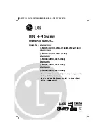
background image

Version 1.1

FWM197

 3141 785 33521

MP3 Mini Hi-Fi System

-/12/05

Published by LX 0942 Service Audio    Subject to modification 

© 

Copyright 2009 Philips Consumer Electronics B.V. Eindhoven, The Netherlands

All rights reserved. No part of this publication may be reproduced, stored in a retrieval

system or transmitted, in any form or by any means, electronic, mechanical, photocopying,

or otherwise without the prior permission of Philips.

CONTENTS

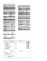
Technical specification ..................................................................1-2

Version variations .........................................................................1-2


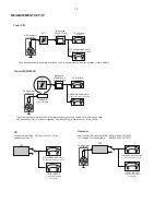
Service measurement setup..........................................................1-3             

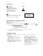
Service aids  .................................................................................1-4          

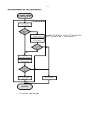
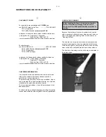
Instructions on CD playability ................................................2-1..2-2

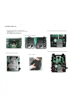
Disassembly diagram............ .......................................................3-1

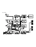
Block diagram ................................................................................4-1

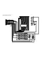
Wiring diagram ..............................................................................4-2 

CD board

     Circuit diagram ..................................................................5-1..5-2 

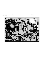
     Layout diagram ..................................................................5-3..5-4

LCD board

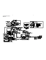
     Circuit diagram .........................................................................6-1 

     Layout diagram ..................................................................6-2..6-3

Cassette board

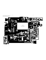
     Circuit diagram .........................................................................7-1 

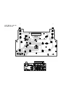
     Layout diagram ..................................................................7-2..7-3

AMP board

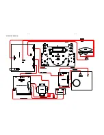
     Circuit diagram .........................................................................8-1

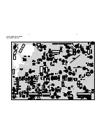
     Layout diagram ..................................................................8-2..8-3

Exploded view diagram .................................................................9-1

Mechanical parts list ......................................................................9-2

Electrical parts list...............................................................10-1..10-2   

Summary of Contents for FWM197/12

Page 1: ...ng or otherwise without the prior permission of Philips CONTENTS Technical specification 1 2 Version variations 1 2 Service measurement setup 1 3 Service aids 1 4 Instructions on CD playability 2 1 2 2 Disassembly diagram 3 1 Block diagram 4 1 Wiring diagram 4 2 CD board Circuit diagram 5 1 5 2 Layout diagram 5 3 5 4 LCD board Circuit diagram 6 1 Layout diagram 6 2 6 3 Cassette board Circuit diagr...

Page 2: ...Distortion 1 Frequency Response 63Hz 16kHz S N Ratio 65dBA General information AC power 220 230V 50 60Hz Operation power consumption 55W Standby power consumption 2W Eco Standby power consumption 1W USB direct Version 2 0 1 1 Dimensions Main Unit W x H x D Speaker Box W x H x D 220 x 292 x 285mm 207 x 292 x 186mm Weight With Packing Main Unit Speaker Box 10 8 kg 2 3 kg 2 x 2 8 kg TECHNICAL SPECIFI...

Page 3: ...15kHz e g 7122 707 48001 LF Voltmeter e g PM2534 DUT S N and distortion meter e g Sound Technology ST1700B Frame aerial e g 7122 707 89001 Tuner AM MW LW To avoid atmospheric interference all AM measurements have to be carried out in a Faraday s cage Use a bandpass filter or at least a high pass filter with 250Hz to eliminate hum 50Hz 100Hz RF Generator e g PM5326 Ri 50 Bandpass 250Hz 15kHz e g 71...

Page 4: ...ng make sure that you are connected with the same potential as the mass of the set via a wrist wrap with resistance Keep components and tools also at this potential ESD CLASS 1 LASER PRODUCT GB Safety regulations require that the set be restored to its original condition and that parts which are identical with those specified be used Safety components are marked by the symbol Lead free ...

Page 5: ...T OK check playability N Y playability ok check playability check playability return set Customer complaint CD related problem fast lens cleaning 1 2 3 For flap loaders access to CD drive possible cleaning method 4 is recommended INSTRUCTIONS ON CD PLAYABILITY 2 1 Exchange CDM 1 4 For description see following pages ...

Page 6: ...viously caused by a scratched dirty or copy protected CD In case problems remain the customer is requested to contact the workshop directly The lens cleaning method 3 should be mentioned in the addendum sheet The final wording in national language as well as the printing is under responsibility of the Regional Service Organizations 4 LIQUID LENS CLEANING Because the material of the lens is synthet...

Page 7: ...oor b Pull out CD door c Press OPEN CLOSE button to close the CD tray power off the mainset and unplug the AC power cord 4 Remove top cabinet 5 Loosen 3 screws PT3X10 and 1 screws PT3X8 to remove CD tray 6 Loosen 14 screws T3 10 and 6 screws PT3x10 to remove CD board 1 2 3 4 5 6 8 7 3 Loosen 6 screws PT3 12 in rear cabinet CD DOOR 1 2 3 4 5 6 5 9 8 7 11 6 12 10 4 3 1 2 13 14 1 2 3 4 5 6 ...

Page 8: ...SET BLOCK DIAGRAM 4 1 4 1 ...

Page 9: ...SET WIRING DIAGRAM 4 2 4 2 ...

Page 10: ...3 VINSD 24 TRB_2 25 VCC1 26 VINTK 27 BIAS 28 MUTE U103 SCA4720 EC114 10U D108 IN4148 D109 IN4148 Q108 8050 R189 22K R191 10K 1 2 3 4 5 CN305 TO LOADER LOADER MOTOR S501 OPEN S502 CLOSE 1 2 3 4 5 CP305 BC136 104 L171 FB 1K L178 FB 1K L200 FB 1K L190 FB 1K L184 FB 1K L182 FB 1K L134 0R L119 0R L136 0R L145 0R L137 0R L144 0R L138 0R L141 0R L139 0R L140 0R L216 FB 1K L217 FB 1K L220 FB 1K L227 FB 1K...

Page 11: ... C197 102 L169 FB L168 FB L1 FB L4 FB C200 102P C201 680P C203 680P C202 680P L6 FB R245 10K R234 10K R230 10K R224 10K R250 10K L170 FB C199 102P D106 IN4148 L165 FB R257 10K C198 102P R8 4 7K R9 1K R10 1K R11 NC D1 IN4148 Q116 8550 R12 10K D2 IN4148 L8 FB L9 FB L10 FB R18 10K R19 10K R20 10K MCU_3V3 CD_CLK CD_STB CD_DATA P_ON REMOTE1 POWER_KEY ECO_LED STANBY_4V MCU_DATA MCU_STB MCU_CLK GND CIRCU...

Page 12: ...LAYOUT DIAGRAM CD BOARD COMPONENT SIDE VIEW 5 3 5 3 ...

Page 13: ...LAYOUT DIAGRAM CD BOARD COPPER SIDE VIEW 5 4 5 4 ...

Page 14: ...7 8 9 10 11 12 13 14 15 16 17 18 19 20 21 22 23 24 25 26 LCD LCD R612 100 R613 10K 1 2 D602 BACKLIGHT LED D601 ECO_WHILE R617 330 B E C Q603 8050 R615 22K R604 100 Q601 8050 R605 22K R610 10K 1 S31 2 S30 3 S29 4 S28 5 S27 6 S26 7 S25 8 S24 9 S23 10 S22 11 S21 12 S10 13 S9 14 S8 15 S7 16 S6 17 S5 18 S4 19 S3 20 S2 21 S1 22 S0 23 CS 24 WR 25 DATA 26 VSS 27 VLCD 28 VDD 29 C0 30 C1 31 C2 32 C3 IC601 E...

Page 15: ...LAYOUT DIAGRAM LCD BOARD COMPONENT SIDE VIEW 6 2 6 2 ...

Page 16: ...LAYOUT DIAGRAM LCD BOARD COPPER SIDE VIEW 6 3 6 3 ...

Page 17: ...CIRCUIT DIAGRAM CASSETTE BOARD 7 1 7 1 ...

Page 18: ...LAYOUT DIAGRAM CASSETTE BOARD COMPONENT SIDE VIEW 7 2 7 2 ...

Page 19: ...LAYOUT DIAGRAM CASSETTE BOARD COPPER SIDE VIEW 7 3 7 3 ...

Page 20: ...CIRCUIT DIAGRAM AMP BOARD 8 1 8 1 ...

Page 21: ...LAYOUT DIAGRAM AMP BOARD COMPONENT SIDE VIEW 8 2 8 2 ...

Page 22: ...LAYOUT DIAGRAM AMP BOARD COPPER SIDE VIEW 8 3 8 3 ...

Page 23: ...EXPLODED VIEW DIAGRAM 10 1 10 1 ...

Page 24: ...SPRING 4 996510021425 CLOCK DISPLAY 41 996510021412 CASS KEYS COVER 42 994000004734 CASS DECK CS 21SC 820T 42 994000004734 CASS DECK CS 21SC 820T 43 996500038818 RECORD SPRING 44 994000004702 7871 CASS DOOR BRACKET 5 996510020747 STOP BUTTON 52 996510029711 TRANSFORMER 05 52 996510002303 TRANSFORMER VDE STD 230V 12 60 996510029708 REAR CAB POWER 62 996510002240 7671 TOP CAB 7 996510020744 PRESET B...

Page 25: ...N 8050C Q114 994000004005 CHIP TR PNP 8550D Q115 994000003972 CHIP TR MMBT9014C Q116 994000004005 CHIP TR PNP 8550D Q117 994000003972 CHIP TR MMBT9014C Q118 994000004004 CHIP TR NPN 8050C Q120 994000004004 CHIP TR NPN 8050C Q123 994000003972 CHIP TR MMBT9014C Q125 994000004005 CHIP TR PNP 8550D U1 996510013449 IC FT24C02 EEPROM SOP8 EP U101 996510021422 IC SST25VF040B SOIC SST U102 996510021426 IC...

Page 26: ...792 TACT SW 6X6MM H4 3 S618 994000004792 TACT SW 6X6MM H4 3 S619 994000004792 TACT SW 6X6MM H4 3 S620 994000004792 TACT SW 6X6MM H4 3 RADIO BOARD ASSEMBLY U1 996510021417 IC SI4730 QFN SILICON LABS X1 996510021421 CRYSTAL SF32 768 JU2620 AMP BOARD ASSEMBLY IC501 996510002288 IC TDA8947J DBS17P SOT243 1 IC502 996510002288 IC TDA8947J DBS17P SOT243 1 IC503 996510002294 IC D4558 SOP8 IC504 9965100022...

Reviews: