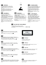
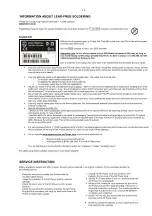
CLASS 1
LASER PRODUCT
©
Copyright 2007 Philips Consumer Electronics B.V. Eindhoven, The Netherlands
All rights reserved. No part of this publication may be reproduced, stored in a retrieval system or
transmitted, in any form or by any means, electronic, mechanical, photocopying, or otherwise without
the prior permission of Philips.
Published by SL0713 Service Audio
Printed in The Netherlands Subject to modifi cation.
GB
3141 785 31680
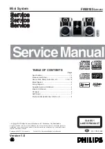
Mini System
TABLE OF CONTENTS
Page
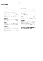
Specifi cations .............................................................. 1-1
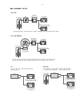
Measurement Setup .................................................... 1-2
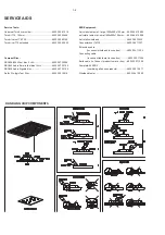
Service Aids, Safety Instruction, etc ..................1-3 to 1-5
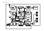
Block Diagram ................................................................ 2
Wiring Diagram ............................................................... 3
Cassette Board & USB Board ........................................ 4
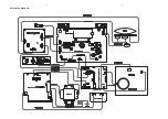
Main & USB Board ......................................................... 5
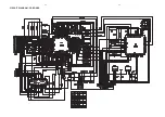
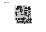
CD Board ........................................................................ 6
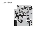
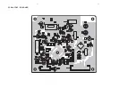
AMP Board ..................................................................... 7
Mechanical Exploded View & Parts List ......................... 8
Version 1.0
FWM185/
05/12/55
Summary of Contents for FWM185/12
Page 6: ...1 6 ...
Page 7: ...2 1 2 1 SET BLOCK DIAGRAM ...
Page 8: ...SET WIRING DIAGRAM 3 1 3 1 ...
Page 9: ...4 1 4 1 PCB LAYOUT CASSETTE BOARD ...
Page 10: ...4 2 4 2 CIRCUIT DIAGRAM CASSETTE BOARD ...
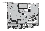
Page 11: ...5 1 5 1 PCB LAYOUT MAIN MCU USB BOARD ...
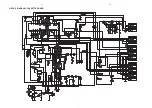
Page 12: ...5 2 5 2 CIRCUIT DIAGRAM MAIN MCU BOARD TUNER PART ...
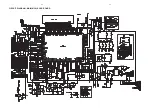
Page 13: ...5 3 5 3 CIRCUIT DIAGRAM MAIN MCU USB BOARD ...
Page 14: ...6 1 6 1 PCB LAYOUT CD BOARD ...
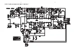
Page 15: ...6 2 6 2 CIRCUIT DIAGRAM CD BOARD ...
Page 16: ...7 1 7 1 PCB LAYOUT AMP BOARD ...