TV rear
connectors
Press
AV+
button on the remote control, then
press
CURSOR V
(down)repeatedly to select
SIDE/SVHS.
Connect the VCR to the TV using
the S-Video cable.
Connect the 2 antenna cables for VCR
Recording. After connecting
all
cables and
devices switch on your TV.
See Set-Top Box
TV rear connector
Press
AV+
button on the remote
control, then press
CURSOR V
(down) until select
AV/SVHS
.
Connect the VCR to the TV using
Video cable (yellow).
Connect the 2 antenna cables for
VCR Recording. After connecting
all
cables and devices switch on your TV.
Composite
Audio / Video
(AV)
Other possible connections for VCR
SERV U
Add for VCR
recording
OUT
Add for VCR
recording
OUT
Add for VCR
recording
Add for VCR
recording
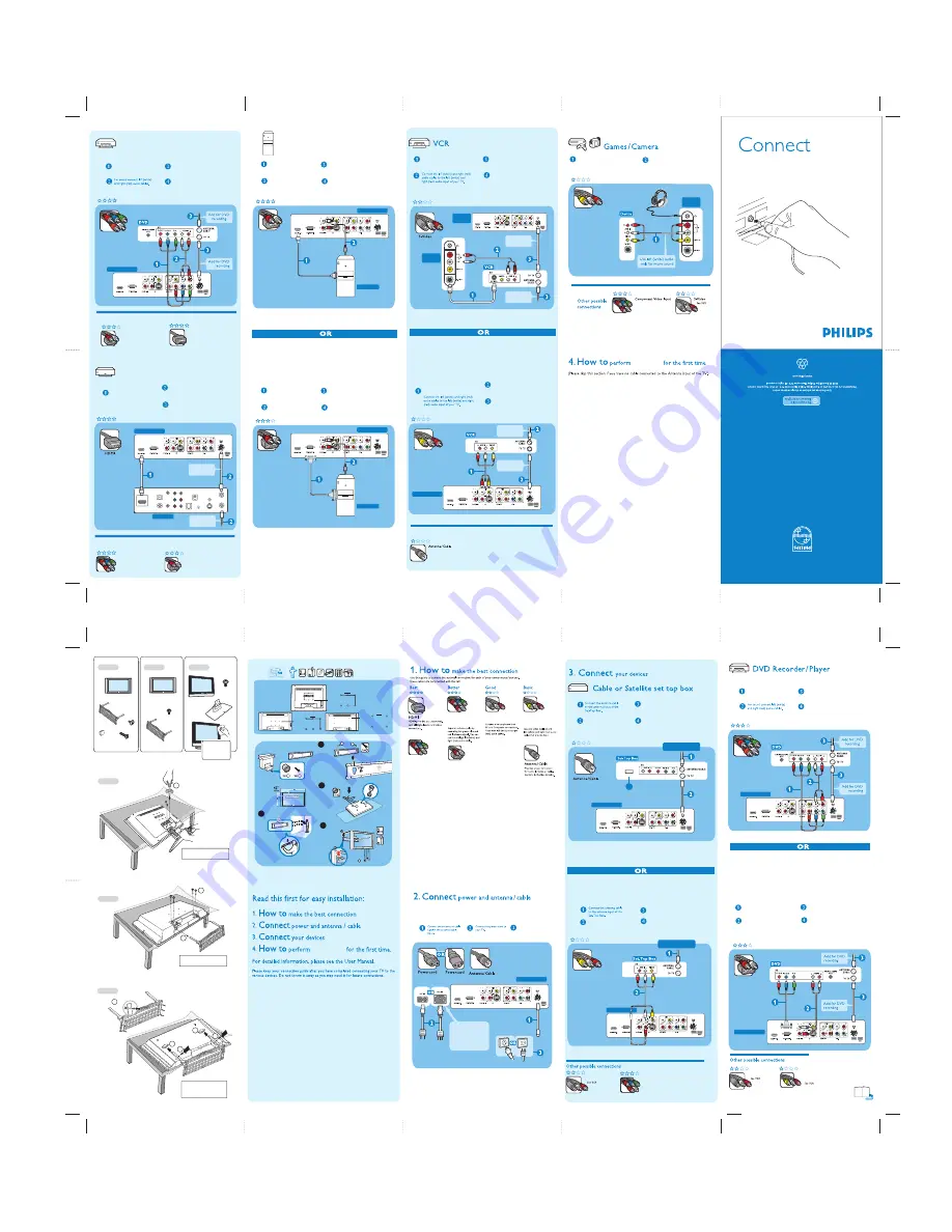
1 When the TV is powered-on for the first time you will have to auto program the TV in
order to receive the channels that are broacasted locally.
2 Press the
MENU
button on the remote control to show the onscreen menu.
3 Press the
CURSOR DOWN
button repeatedly until
Install
is highlighted.
4 Press the
CURSOR RIGHT
button to enter the
Install
menu. Language will be highlighted.
5 Press the
CURSOR DOWN
button repeatedly until
Auto Program
is selected. “
Start ?
”
will appear.
6 Press the
CURSOR RIGHT
button to start the Auto Programing process.
7 Press the
STATUS/EXIT
button to remove the menu from the screen when the Auto
programing process has finished.
programing
Composite
Audio / Video
(SIDE)
/ Headphone
Press the
AV+
button on the remote control
then press
CURSOR V
(down) to select
SIDE/
SVHS
.
AV OUT
x 1
x 4
3
1
x 3
26PF5321
x 1
x 1
32PF5321
42PF7321
A
B
Please be aware that the side Audio/Video
connectors are difficult to access and use
when connecting standard cables.
Please handle with
care. Use only the
soft cloth provided,
to clean the glossy,
black front of the TV.
x 1
x 6
x 2
x 1
32PF5321
Í
VESA
42PF7321 800 x 400 mm
Í
26PF5321
32PF5321
42PF7321
Please be aware that when you mount
your TV on the wall using the key hole
system, the side Audio/Video connectors
are difficult to access and use when
connecting standard cables.
x 2
B
A
A
B
B
C
C
Í
26PF5321
x 1
VESA
100mm
100mm
100mm
VESA
100mm
100mm
100mm
2
4
Please be aware that the side Audio/Video
connectors are difficult to access and use
when connecting standard cables.
1249
415
117
688
FOR VESA MOUNTING
(NOT INCLUDED)
FOR WALL MOUNTING
(INCLUDED ONLY FOR 42PF7321)
A
B
B
B
B
A
A
A
B
TV rear connector
programing
Component
Video Input
(CVI)
S-Video
(SVHS)
Composite
Audio / Video
(AV or SIDE)
connection from your AV
equipment.
VGA (PC-VGA or
CVI-2 SD/HD)
Connect to your PC via VGA
connector. It can be also used
to connect a Progressive Scan
device (using the YPbPr-VGA
adapter)
Progressive Scan input
(CVI-1 SD/HD)
Provide superior picture quality
when using a Progressive Scan
signal in HD mode via Y-Pb-Pr
connector.
It can be also used to connect a
PC via DVI connector.
CAUTION
: This is a
Class 1 apparatus. It
must be connected to a
MAINS socket out with
a protective earthing
connection.
42PF7321
26PF5321
32PF5321
TV rear connector
TV rear connector
Connect the Set-Top Box to
the TV using an antenna cable.
Tune in the TV the same
channel selected in the Set-Top
Box.
Press
AV+
button on the remote
control, then press
CURSOR V
(down) repeatedly to select
AV/SVHS
.
Connect the Set-Top Box to the
TV using Composite Video (AV)
plug into their corresponding
jacks.
S-Video (SVHS)
OUTPUT CH
4
SERV U
SERV U
Composite
Audio / Video
(AV)
Component Video
Input (CVI)
Signal input Cable from
the Cable Provider
Signal input Cable from
the Cable Provider
OUT
See DVD Recorder/Player
TV rear connector
TV rear connector
Press
AV+
button on the remote
control, then press
CURSOR V
(down) repeatedly to select
CVI-1
(HD/SD)
.
Connect the DVD to the TV
using
YPbPr - VGA adapter
.
Press
AV+
button on the remote
control, then press
CURSOR V
(down) repeatedly to select
CVI-2
(SD/HD).
Connect the DVD to the TV using
Component Video cable.
Component
Video Input
(CVI-1 SD/HD)
Component Video
Input via VGA
(CVI-2 SD/HD)
S-Video (SVHS)
SERV U
SERV U
Turn your page to see other connections.
OUT
3139 125 36161
HD Receiver
TV rear connector
HD receiver
Connect the antenna cables for
recording on your HD receiver.
Connect the component video jacks
from the HD receiver to the
HDMI
/ PC-D
of the TV using a
HDMI
cable.
Press
AV+
button on the remote
control, then press
CURSOR V
(down) repeatedly to select
HDMI
.
PC (Monitor)
TV rear connector
PC (Monitor)
Connect the audio output on the
PC to the
PC AUDIO In
of the
TV using an audio cable as shown.
Connect the Monitor (video) output
on the PC to the
HDMI/PC-D
Input
of the TV using a
HDMI to
DVI cable
.
Press the
AV+
button on the
remote control then press
CURSOR V
(down) to select
PC-D
.
PC-D input
RF
REMOTE
PHONE JACK
SATELLITE IN
OUT TO TV
CH 3
CH 4
DIGITAL
AUDIO OUT
VCR
CONTROL
S-VIDEO
VIDEO
in 2
L
AUDIO
VIDEO
in 1
R
L
AUDIO
OUT
PB
PR
Y
VIDEO
OUT
IN FROM ANT
Other possible connections for HD receiver
See DVD Player with
Progressive Scan Output
Progressive Scan Input
(CVI-1 SD/HD)
SERV U
Add for
recording
Add for
recording
HDMI OUT
TV rear connector
PC (Monitor)
Connect the audio output on the
PC to the
PC AUDIO In
of the
TV using an audio cable.
Connect the Monitor (video) output
on the PC to the
PC-VGA/CVI-2
Input
of the TV using a
VGA
cable
.
Press the
AV+
button on the
remote control then press
CURSOR V
(down) to select
PC-VGA
.
SERV U
VGA
TV rear connector
Press
AV+
button on the remote
control, then press
CURSOR V
(down) repeatedly to select
CVI-1
(HD/SD)
.
Connect the DVD to the TV using
Component Video cable.
Progressive
Scan Input
(CVI-1 SD/HD)
SERV U
OUT
Composite
Audio/Video (AV)
OUT
TV side
connectors
Connect the Video cable from the Video output
on your camera or game console to the video
input located on the side of your TV. Connect the
left (white) and right (red) audio cables for sound.
TV side
connectors
Note : For headphone connection, please insert
the plug into the headphone socket as shown.
DVD Player with Progressive
Scan Output
Tighten
B
Other possible connections for DVD Player with Progressive Scan Output
See DVD Recorder / Player
Progressive Scan Input via
VGA (CVI-2 SD/HD)
See HD Receiver
HDMI
See DVD Recorder / Player
See DVD Recorder / Player
Progressive Scan Input via
VGA (CVI-2 SD/HD)
Connect the 2 antenna cables for
DVD Recording. After connecting
all
cables and devices switch on your TV.
After connecting all cables and
devices switch on your TV.
After connecting
all
cables and
devices switch on your TV.
After connecting
all
cables and
devices switch on your TV.
After connecting
all
cables
and devices, plug in the power
and switch on your TV.
After connecting
all
cables and
devices, switch on your TV.
After connecting all cables and
devices switch on your TV.
Connect the 2 antenna cables for
DVD Recording. After connecting
all
cables and devices switch on your TV.
For sound connect the left (white) and
right (red) audio cables to the left
(white) and right (red) audio input of
your TV
(PC AUDIO IN).
Connect the 2 antenna cables for
DVD Recording. After connecting
all
cables and devices switch on your TV.