
DSATX Manual
Copyright 2006 Mpegbox.com
Page 1 of 13
DuraWatt DSATX
220-Watt DC-DC ATX Power Supply
User Manual
Version 1.0
Table of Contents
1.
Getting Started ...............................................................................................................................1
1.1.
Introduction ....................................................................................................................................1
1.2.
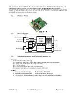
Product Photo .........................................................................................................................2
1.3.
Block Diagram.........................................................................................................................2
1.4.
Included Contents and Optional Accessories ............................................................................2
2.1.
Recommended Additional Supplies ..........................................................................................3
2.2.
Recommended Tools...............................................................................................................3
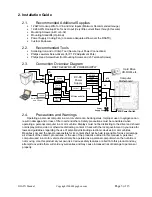
2.3.
Connection Overview Diagram.................................................................................................3
2.4.
Precautions and Warnings.......................................................................................................3
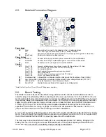
2.5.
Detailed Connection Diagram ..................................................................................................4
2.6.
Bench Testing .........................................................................................................................4
2.7.
Quick Installation Steps ...........................................................................................................5
3.
User Guide......................................................................................................................................5
3.1.
Theory of Operation.................................................................................................................5
3.2.
Modes of Operation .................................................................................................................5
3.3.
LED Codes .............................................................................................................................6
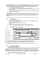
3.4.
Basic Mode Timing Diagram ....................................................................................................6
3.5.
Features Explained..................................................................................................................6
4.
Serial Port Connectivity..................................................................................................................8
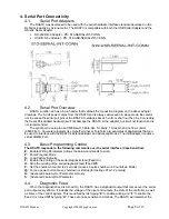
4.1.
Serial Port Adapters ................................................................................................................8
4.2.
Serial Port Overview ................................................................................................................8
4.3.
Basic Programming Control .....................................................................................................8
4.4.
Diagnostic Feed ......................................................................................................................8
4.5.
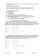
Extended Basic Programming Examples ..................................................................................9
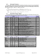
4.6.
Advanced Features ...............................................................................................................10
4.7.
Advanced Feature Tables ......................................................................................................10
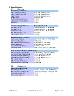
5.
Specifications...............................................................................................................................11
5.1.
Electrical ...............................................................................................................................11
5.2.
Mechanical............................................................................................................................11
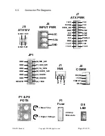
5.3.
Connector Pin Locations........................................................................................................12
7.
Mpegbox.com Limited Warranty ..................................................................................................13
1. Getting Started
1.1.
Introduction
Thank you for purchasing a DSATX 220 Watt Automotive Power Supply. Please take some time to read
through this manual before attempting to use this product.
The DSATX is the most advanced DC-DC Automotive Computer Power Supply available. It is capable of
properly powering most Pentium 4 and AMD based computers in a motor vehicle as well as their accessories.
Its advanced microprocessor control enables features such as Startup/Shutdown Sequencing, Low Voltage


