background image

CD CONNECTOR PCB COMPONENT LAYOUT.......................16

TUNER PCB COMPONENT LAYOUT........................................14-15

TROUBLE  SHOOTING................................................................19-20

SET EXPLODER VIEW DRAWING.............................................18

ISO PCB COMPONENT LAYOUT..............................................17
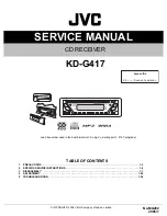
CEM2101G/51

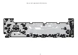
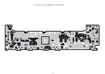
PANEL PCB COMPONENT LAYOUT.......................................12-13

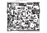
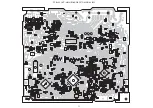
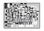
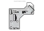
MAIN PCB COMPONENT LAYOUT.........................................10-11

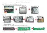
DISMANTLING INSTRUCTIONS............................................2

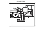
CIRCUIT DIAGRAM TUNER BOARD.......................................9

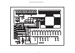
CIRCUIT DIAGRAM PANEL BOARD......................................8

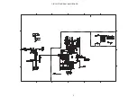
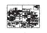
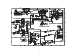
CIRCUIT DIAGRAM MAIN BOARD.......................................5-7

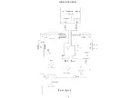
WIRING DIAGRAM.................................................................4

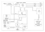
BLOCK DIAGRAM...................................................................3

2012-6-15


Service  Manual

RECORDABLE

REWRITABLE

Mini  System

Service

Service

Version1.0

TABLE  OF  CONTENTS


Summary of Contents for CEM2101G/51

Page 1: ...LAYOUT 17 CEM2101G 51 PANEL PCB COMPONENT LAYOUT 12 13 MAIN PCB COMPONENT LAYOUT 10 11 DISMANTLING INSTRUCTIONS 2 CIRCUIT DIAGRAM TUNER BOARD 9 CIRCUIT DIAGRAM PANEL BOARD 8 CIRCUIT DIAGRAM MAIN BOARD 5 7 WIRING DIAGRAM 4 BLOCK DIAGRAM 3 2012 6 15 Service Manual RECORDABLE REWRITABLE Mini System Service Service Version1 0 TABLE OF CONTENTS ...

Page 2: ...e 2 Remove B C screws in left and right side of metal bracket Then remove D E screws in panel base Remove deck mechanism 0 7 2 2 6 66 0 1 0 5HPRYH WKH ILYH VFUHZV LQ EDFN SDQHO DQG VHSDUDWH EDFN SDQHO IURP IURQW SDQHO 7DNH RXW WKH EDFN SDQHO DQG WKHQ WDNH RXW 3 ERDUG ϔǃThe procedure of disassembling the unit ѠǃThe procedure of disassembling the panel EJ䪂 A B D E C 2 ...

Page 3: ...3 ...

Page 4: ...WIRING DIAGRAM 4 ...

Page 5: ...5 CIRCUIT DIAGRAM MAIN BOARD ...

Page 6: ...6 ...

Page 7: ...7 ...

Page 8: ...5 6 63 6 6281 6 1 6 6 6 6 83 21 5 5 5 5 5 5 5 5 1 5 1 5 5 5 5 5 5 5 8 5 5 5 5 5 5 5 5 5 5 5 5 5 5 5 5 8 8 8 8 8 8 8 8 8 8 8 8 8 8 8 9 9 9 9 3 3 3 3 5 5 5 5 3 8 8 S S 1 1 5 6 1 5 5 8 7 8 4 5 N 5 N 0 0 5 0 0 5 0 0 5 0 0 5 8 5 6 6 6 6 6 6 6 6 6 6 6 6 6 6 6 6 6 6 6 6 6 6 6 6 6 6 6 6 6 6 6 6 6 6 6 6 6 6 6 6 6 6 6 6 6 6 6 6 6 6 6 6 6 6 6 6 6 6 6 6 6 6 6 6 6 6 6 6 6 6 6 6 6 6 6 6 6 6 6 6 6 6 6 6 6 6 6 6 ...

Page 9: ...03 47 XT001 32 768KHz C009 22P C112 103 C020 104 12 11 10 9 8 7 6 5 4 3 2 DATA CLK RES R OUT L OUT GND DGND RFGND FM ANT 3V3 RDS 1 RFGND CN001 TUNER23 C015 104 L007 220UH C013 333 C019 474 L004 FB152 Q004 9014S Q102 Q003 9014S Q002 9018S R006 220K R005 10M C017 183 L006 33UH L005 1MH C014 122 R004 10K R007 4K7 R008 4K7 C016 474 R010 10 C021 1U C020 104 C007 104 AM C018 104 R009 10K L008 FB152 EC00...

Page 10: ...PCB LAYOUT MAIN BOARD TOP SIDE VIEW 10 ...

Page 11: ...PCB LAYOUT MAIN BOARD BOTTOM SIDE VIEW 11 ...

Page 12: ...PCB LAYOUT PANEL BOARD TOP SIDE VIEW 12 ...

Page 13: ...PCB LAYOUT PANEL BOARD BOTTOM SIDE VIEW 13 ...

Page 14: ...4 1 PCB LAYOUT TUNER BOARD TOP SIDE VIEW ...

Page 15: ...15 PCB LAYOUT TUNER BOARD BOTTOM SIDE VIEW ...

Page 16: ...16 PCB LAYOUT CD CONNECTOR TOP SIDE VIEW ...

Page 17: ...17 PCB LAYOUT ISO BOARD BOTTOM SIDE VIEW ...

Page 18: ...SET EXPLODER VIEW DRAING 18 ...

Page 19: ...ther the connection of 8PIN audio output wire of ISO connector is correct wrong connection or short circuit to the ground will caused the protection of the power amplifier no voltage output NO Power a To check whether the volume knob is turn to the minimum position g To check Panel LED 5V voltage should be normal a To check whether it is connect well of the ISO connector 4PIN power input Whether i...

Page 20: ...voltage of the first pin of main board IC604 should be 3V3 when insert USB the voltage of the second pin should be 3V if no insert the USB the voltege should be 0V failure cause failure remark GHIHFWLYH m To check whether the rotation belt of deck mechanism is dislocation or loose b To check whether there is any abnormal of the rotation of the deck mecahnism or whether the disc is enter in positio...

Reviews: