background image

©

 Copyright 2009 Philips Consumer Electronics B.V. Eindhoven, The Netherlands

All rights reserved.  No part of this publication may be reproduced, stored in a retrieval system or 
transmitted, in any form or by any means, electronic, mechanical, photocopying, or otherwise without 
the prior permission of Philips.
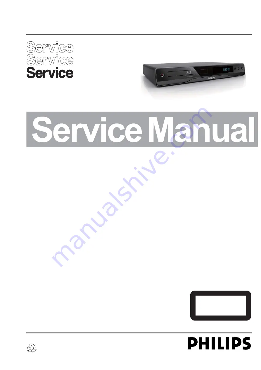
Blu-ray Disc Player

CLASS 1

LASER PRODUCT

©

TABLE OF CONTENTS

Page

Technical Specifi cations ....................................................... 1-2

Safety Instruction, Warning & Notes ..................................... 1-3

QSG & DFU Instruction ........................................................... 2

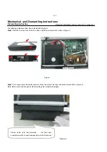
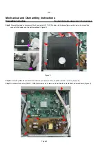
Mechanical and Dismantling Instructions ................................ 3

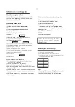
Software Version & Upgrades, Region Code Change ............. 4

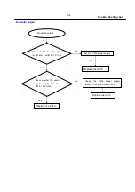
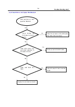
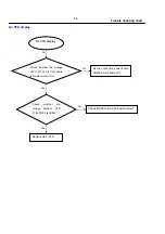
Trouble Shooting Chart ........................................................... 5

Set Wiring Diagram ................................................................. 6

Electrical Diagrams and PCB layouts ...................................... 7

Set Mechanical Exploded view & Parts List ............................ 8

Revision List ............................................................................ 9

Published by SL 094

5

BU AVM        Printed in The Netherlands        Subject to modification

BDP2500

3141 785 34433

/12/05/98

/51

Version 1.3

Summary of Contents for BDP2500

Page 1: ... ray Disc Player CLASS 1 LASER PRODUCT TABLE OF CONTENTS Page Technical Specifications 1 2 Safety Instruction Warning Notes 1 3 QSG DFU Instruction 2 Mechanical and Dismantling Instructions 3 Software Version Upgrades Region Code Change 4 Trouble Shooting Chart 5 Set Wiring Diagram 6 Electrical Diagrams and PCB layouts 7 Set Mechanical Exploded view Parts List 8 Revision List 9 Published by SL 0945...

Page 2: ... V DGGLWLRQDO PHPRU IRU VRIWZDUH XSGDWHV DQG RQXV9LHZ FRQWHQWV 1RW IRU PHGLD SOD Main unit 3RZHU VXSSO UDWLQJ XURSH a 9 a a 3RZHU FRQVXPSWLRQ 3RZHU FRQVXPSWLRQ LQ VWDQGE PRGH LPHQVLRQV Z K G PP 1HW HLJKW NJ Accessories supplied 5HPRWH FRQWURO DQG EDWWHULHV XGLR 9LGHR FDEOHV User manual DVHU 6SHFLÀFDWLRQ DVHU 7 SH DVHU LRGH Q D1 D1 9 DVHU LRGH Q D 3 DVHU LRGH D V DYH OHQJWK QP QP 9 QP QP QP QP 2XWS...

Page 3: ... wire between the two pins of the mains plug 2 Set the mains switch the on position keep the mains cord unplug 3 Measure the resistance value between the mains plug and the front panel controls and chassis bottom 4 Repair or correct unit when the resistance measurement is less than 1M 5 Verify this before you return the unit to the customer user ref UL standard no 1492 6 Switch the unit off and re...

Page 4: ...ch copper tracks and or components in this unshielded primary area when you service the player Service personnel must take precautions to prevent touching this area or components in this area A lighting stroke and a stripe marked printing on the printed wiring board indicate the primary side of the power supply Never replace modules or components while the unit is on 2 Laser The use of optical ins...

Page 5: ...ch off un used equipment or reduce heat x Mix of lead free solder alloy parts with leaded solder alloy parts is possible but PHILIPS recommends strongly to avoid mixed solder alloy types leaded and lead free If one cannot avoid clean carefully the solder joint from old solder alloy and re solder with new solder alloy SAC305 x Use only original spare parts listed in the Service Manuals Not listed s...

Page 6: ... Description LOADING RDGLQJ D GLVF UNSUPP The disc is not supported BD OX UD GLVF LV UHFRJQL HG HDMI ERR 7KH 0 YLGHR UHVROXWLRQ LV QRW VXSSRUWHG E 79 FASTFWD DVW IRUZDUG PRGH FASTBWD Fast reverse mode SLOWFWD 6ORZ IRUZDUG PRGH SETTINGS Setup menu is displayed HOME RPH PHQX LV GLVSOD HG CHAPTER XUUHQW FKDSWHU LV LQ FKDSWHU UHSHDW PRGH DOLBY D Dolby Digital audio is being played DOLBY HD ROE DXGLR L...

Page 7: ...6NLS WR WKH SUHYLRXV RU QH W WLWOH FKDSWHU RU WUDFN j 6HDUFK EDFNZDUG RU IRUZDUG k 0XWH YROXPH DSSOLFDEOH RQO WR FHUWDLQ 3KLOLSV EUDQG 79V l GMXVW YROXPH DSSOLFDEOH RQO WR FHUWDLQ 3KLOLSV EUDQG 79V m SUBTITLE Select a subtitle language on a disc n AUDIO Select an audio language or channel on a disc o Alphanumeric buttons Select an item to play Enter values p Open or close the disc compartment q TV...

Page 8: ...the Top Cover Figure 1 Figure 1 Step2 If it is necessary to dismantle Loader or Front Panel the Front door should be removed first Figure 2 Note Make sure to operate gently otherwise the guider would be damaged Figure 2 3 1 Please kindly note that dismantle the front door assembly carefully to avoid damage tray and the front door Detailed information please refer to the model set ...

Page 9: ...ate gently otherwise the guider would be damaged Figure 3 Step4 Dismantling Front Panel disconnect the connectors J306 CN502 need release 3 snaps of Front Panel Figure 4 3 2 Detailed information please refer to the model set and 2 snaps of bottom cabinet and cut off 2 twist tie then gently pull the Panel out from the set Figure 4 Figure 6 J317 J320 J306 PWR1 CN502 CN504 CN501 Twist tie ...

Page 10: ...ain Board first disconnect the connector and then remove 4 screws Figure 6 Step7 Disconnect connector CN501 CN504 and remove 4 screws on Power Board to dismantle the Power Board Figure 6 Step5 Dismantling Loader disconnect the 2 connector J317 J320 aiming in the below figure and remove 4 screws that connects the loader and the bottom cabinet Figure 5 PWR1 ...

Page 11: ...Cancel Start damaged entirely 4 Press Right cursor button to choose Start then press OK 5 The software will updagrde and screen will display as below Upgrade is ongoing Please wait Please do not unplug or switch off the device DVD Region code change 6 The screen will display as below when upgrading complete Upgrade has completed successfully 1 Power on the set and keep no disc Power off after 1s 2...

Page 12: ...rrive the front board U4 s pin 6 8 9 connect condition Correct connection Replace U4 or VFD Yes Yes Yes No Check5V 12V 12V voltage on the power and front board Check the front board signalsVSTBˈVCLK VD 1 Check whether bad solder exists on the front board U4 and pins of VFD 2 Check whether the circuit connected to K1 K2 K3 K4 K5 K6 is broken Fix the connection JP1 on front board and CN504 on power ...

Page 13: ...ply U916 4 12V and U916 8 12V Check whether the audio signal is right from the U916 7 and U916 1 Yes No Go Check whether the audio signal is right from the U915 9 10 11 12 No audio output Trouble shooting chart 5 2 Replace the U915 Replace the U916 Yes Yes Replace the U916 ...

Page 14: ...e the battery for remote controller Check whether the remote controller s battery is exhausted or Not Check the IR1 power supply is OK IR1 3 is about 5V Check the VCC net No front board Yes Trouble shooting chart 5 3 Check the IR output of U2 1 Check the VCC of U2 Yes Replace U2 IR1 ...

Page 15: ...sc or can t open the disk door Check SATA cable from main board connection to the loader is Normal No GO Check whether the DVD loader running is Normal Fix the connection the SATA cable No Yes Trouble shooting chart 5 4 No Check main board and loader Check the power of main board and loader Yes Replace the main board and loader ...

Page 16: ... VFD F2 is AC24V Go No No No VFD display Yes Fix the connection power board CN502 front board JP1 Check whether the voltage 5V 12V on the front board is Normal work or Not Check DC5V to AC 24V switch circuit Replace U4 or VFD Yes Trouble shooting chart 5 5 ...

Page 17: ... HDMI Component ResetBtn P 5 P 6 P 6 P 8 P 8 CLOCK DDR2 1L DDR2 1H DDR2 0L DDR2 0H P 4 AUD CON DC DC 3 3V NAND FLASH 5V GND GND 12V PSU front board IR_IN ACK GND VSTB VCK VD POW_SW GND LED 2 LED switch board ASA LOADER 5V GND GND 12V SATA serial flash BDP2500 Wiring Diagram 6 1 6 1 ...

Page 18: ...4 GND 5 C15 100pF R43 100 C1 0 1uF R34 1K R36 10K NC R10 10K U4 PT6312 SW1 1 SW2 2 SW3 3 SW4 4 SDout 5 SDin 6 GND 7 SCLK 8 CS 9 KEY1 10 KEY2 11 KEY3 12 KEY4 13 VDD 14 SEG1 K1 15 SEG2 K2 16 SEG3 K3 17 SEG4 K4 18 SEG5 K5 19 SEG6 K6 20 SEG7 21 SEG8 22 SEG9 23 SEG10 24 SEG11 25 SEG12 26 VEE 27 SEG13 28 SEG14 29 SEG15 30 SEG16 31 G6 32 G5 33 G4 34 G3 35 G2 36 G1 37 VDD 38 LED4 39 LED3 40 LED2 41 LED1 4...

Page 19: ...A A B B C C D D E E 1 1 2 2 3 3 4 4 POW_SW SWITCH BOARD C1 47pF LED1 LED03R C2 47pF K1 TAC020 XP1 4PIN 2 0mm 1 1 2 2 3 3 4 4 Switch Board Electric Diagram 7 2 7 2 ...

Page 20: ... 1 L 2 R522 390 R504 22 R505 33K R517 470k CY504 102 400Vac ZD503 24V 1 2W PAS R533 10k F501 T2AL 250Vac PAS ZD501 22V 0 5W PAS C508 0 1uF PAS PAS C503 100PF R507 1M 1206 1 U503 TL431 2 1 3 PAS PAS R524 1k R508 1M 1206 1 FB501 2 2uH R516 100k C501 103 1KV R535 100 D507 RL207 CE501 100uF 400V D506 RL207 R514 150 OHM 0805 U501 NCP1271 RT 1 COMP 2 CS 3 GND 4 OUT 5 VCC 6 NC 7 HV 8 R502 0 82 OHM 2W Q50...

Page 21: ... 6 GND 7 PH 8 CB1003 0 1uF Q208 AO3401 AO3401 1 2 3 CB955 open CTP8 CB993 0 1uF FB570 0805 L R1259 NC 68 1K C3 0 1uF FB566 FB 0805 R1341 NC 68 1K FB569 0805 L CB1000 0 1uF CE576 220uF 6 3v U909 TPS54331D BOOT 1 VIN 2 EN 3 SS 4 VSNS 5 COMP 6 GND 7 PH 8 CE579 220uF 10v CB992 0 1uF CB1001 0 1uF 0603 C CE577 220uF 16V R1257 8 1K 1 CE6 100uF 10v CB997 0 1uF CE566 220uF 10V CE563 220uF 10v C603 5600pF C...

Page 22: ...2 AC15 ARAS AC12 ACAS AE12 ACKE AC16 ARCS Y11 ARWE AA15 ARCLK AE11 ARCLK1 AE23 ARCLKB AF11 ARCLKB1 AF23 REXTDN AD26 REXTUP AF24 VDD_ARVREF AA16 VDD_ARVREF AB16 VCC18IO H21 VCC18IO H23 VCC18IO J22 VCC18IO J24 VCC18IO P21 VCC18IO P23 VCC18IO R22 VCC18IO R24 VCC18IO Y21 VCC18IO Y23 VCC18IO AA8 VCC18IO AA14 VCC18IO AA20 VCC18IO AA22 VCC18IO AA24 VCC18IO AB9 VCC18IO AB15 VCC18IO AB21 VCC18IO AB23 VCC18...

Page 23: ...S M15 DVSS M16 DVSS M22 DVSS M24 DVSS N10 DVSS N12 DVSS N13 DVSS N14 DVSS N15 DVSS N17 DVSS P10 DVSS P12 DVSS P13 DVSS P14 DVSS P15 DVSS P17 DVSS R11 DVSS R12 DVSS R13 DVSS R14 DVSS R15 DVSS R16 DVSS T12 DVSS T15 DVSS U10 DVSS U13 DVSS U14 DVSS U17 DVSS U21 DVSS U23 DVSS V22 DVSS V24 DVSS AA11 DVSS AA17 DVSS AA21 DVSS AB6 DVSS AB12 DVSS AB18 DVSS AB22 DVSS AC6 DVSS AC11 DVSS AC17 DVSS AC23 DVSS AD...

Page 24: ... AOSDATA1 C9 AOSDATA2 B9 AOSDATA3 B8 AOSDATA4 A8 AOSDATA5 D9 AOMCLK A10 AOBCK B10 AOLRCK D10 SPDIF C8 MCIN A7 AMUTE C7 RESET W5 CEC D11 HTPLG E12 HDMISD C10 HDMISCK E11 CH2_P A11 CH2_M B11 CH1_P A12 CH1_M B12 CH0_P A13 CH0_M B13 CLK_P A14 CLK_M B14 AVDD10_HDMI C12 AVSS_HDMI C11 AVSS_HDMI D12 AVSS_HDMI D13 AVDD33_HDMI C13 AVDD33_HDMI C14 EXT_CAP A15 EXT_RES B15 IOR B19 IOB B20 IOG A20 IOX C20 IOC A...

Page 25: ... C24 NFALE B24 NFCLE C23 PMOEN E2 PMVS1N E1 PMCD1N E4 PMD7 D2 PMA7 D1 PMA4 D3 PMCE1N E3 PMREGN H1 PMWAITN G1 PMVS2N G2 PMRDY G3 PMWEN F2 PMWRN F3 PMRDN H5 PMRST H3 PMA6 F5 PMBVD2 H4 PMBVD1 H2 PMCE2N G4 RTCK AB1 TDO AA1 TRST AC1 TDI AB2 TMS AA3 TCK Y4 IR AF2 SFCS B23 SFCK A23 SFDI C22 SFDO D21 SFCS2 B22 SD2CLK A2 SD2CMD A1 SD2D0 B2 SD2D1 B1 SD2D2 C2 SD2D3 C1 UATXD AA2 UARXD Y3 VSTB AE4 VDATA AD5 VC...

Page 26: ...10K CE303 220uF 16v C316 4 7uF 0805 C CB320 0 1uF Q211 AO3402 1 2 3 CB319 0 1uF 0402 C TP1033 CB342 0 1uF R1176 10K CB321 0 1uF TP1019 CB345 0 01uF R1175 10K NC R1260 4 7K CTP48 FB309 FB 0603 R1170 100R CB337 0 1uF 1 GND 2 D 3 D 4 VCC 4 2 3 1 P503 USB TYPEA 2 3 4 1 5 6 TP978 TP1032 CB333 0 01uF R1179 10K CB963 0 1uF R360 33R R359 33R CB329 0 1uF CE307 470uF 10V R1180 10K NC R1174 10K NC CB318 0 1u...

Page 27: ...347 75 1 CTP18 R535 100_1 D522 DIODE SMD BAV99 1 2 3 0 1UF C609 16V 10 1 2 C626 100PF CTP19 CTP39 CB1009 33pF NC R W W R P502 RCA2X2 RCA 407 1 2 3 4 5 6 R1354 150R C510 10pF D520 DIODE SMD BAV99 1 2 3 CTP38 Q212 BT3904 0 1UF C610 16V 10 1 2 R501 100R D521 DIODE SMD BAV99 1 2 3 R1262 75 1 CE605 47uF 16v R536 91_1 R1345 75 1 C501 100pF CB500 0 1uF C509 10pF R1403 33R 0 R1263 NC 0 R1398 2 4K CB1006 3...

Page 28: ...F R1371 470R Q217 BT3904 R1382 5 1K 1 R1380 100K Q220 BT3904 R1358 100R R1368 22K R1378 470R CTP37 CTP35 C625 4 7uF CTP26 R1381 4 7K 1 C621 0 1uF C617 470pF Q216 BT3904 R1395 470R J319 4x1 CONS4 XP 1 2 3 4 R1375 470R R1388 100K U915 AK4385ET DZFR 15 DZFL 16 PDN 5 BICK 2 MCLK 1 VDD 14 VSS 13 SDTI1 3 CSN 6 CDTI 8 CCLK 7 AOUTR 10 AOUTL 12 AOUTR 9 AOUTL 11 LRCK 4 C624 NC R1362 330R C616 0 1uF CTP27 R1...

Page 29: ...3A1 30 TXP 29 SPEED100 PHYAD0 9 VSS FLAG 37 RXP 32 RXN 31 LINK PHYAD1 10 ACTIVITY PHYAD2 11 FDUPLEX PHYAD3 12 VDD33 7 VDD_CORE 8 CLKIN XTAL1 14 XTAL2 13 VDDIO 25 RXD0 MODE0 18 RX_DV 19 RX_CLK REGOFF 20 RX_ER RXD4 21 VDD33A2 33 VDD33A3 35 R1310 100R R1316 NC 10K R1329 12 4K 1 R1298 100R CB989 NC 0 1uF 0603 C R1326 1M R1296 0R CB975 0 1uF CB979 0 1uF R1325 10K R1289 49 9 1 16W 1 0603 R R1311 100R R1...

Page 30: ...Front Board PCB layout Top and Bottom side 7 13 7 13 ...

Page 31: ...7 14 7 14 Power Board Electric Diagram Switch Board Electric Diagram ...

Page 32: ...Main Board Print layout Top side 7 15 7 15 ...

Page 33: ...Main Board Print layout Bottom side 7 16 7 16 ...

Page 34: ...8 2 Exploded view for BDP2500 12 51 It s a general mechanical exploded view for BDP2500 12 51 and pls refer to the model set for detailed information Assy1 includes components 2 3 4 6 7 ...

Page 35: ...8 2 Exloded view for BDP2500 05 It s a general mechanical exploded view for BDP2500 05 and pls refer to the model set for detailed information Assy1 includes components 2 3 4 6 7 ...

Page 36: ...8 2 Exploded view for BDP2500 98 It s a general mechanical exploded view for BDP2500 98 pls refer to the model set for detailed information Assy1 includes components 2 3 4 6 7 18 19 20 21 ...

Page 37: ...D TRANSMISSION LINE 1 J320 996510025852 4PIN CABLE TJC3 4Y 2 1 JP1 996510025834 CABLE 5P 130MM FH JC20 1 JP3 996510027138 4P cbl 1 JP2 996510030213 6PIN 2 0MM 280MM PH JC20 1 RC 996510025848 REMOTE CONTROL 1 SATALINE 996510029499 SATA CABLE 1 Screws List No 12NC No Description Q ty 12 ST SCREW B 3 0 X 6 BLACK 11 15 S T SCREW B 3 X 8 BF 1 16 M C SCREW 3 X 6 B 1 20 ST SCREW B 3 0 X 7 SILVER 4 21 S T...

Page 38: ...6510009669 SMD TRANSISTOR MMBT3904LT1 NPN 1 No 12NC No Description Q ty Q213 996510009670 TRANSISTOR SMT 3CG9012M 1 11 996510029508 BOTTOM CABINET 1 Q214 996510009670 TRANSISTOR SMT 3CG9012M 1 14 996510030372 BACK PANEL 1 Q215 996510009669 SMD TRANSISTOR MMBT3904LT1 NPN 1 18 996510029503 TOP COVER 1 Q216 996510009669 SMD TRANSISTOR MMBT3904LT1 NPN 1 AVCABL 996500020384 AUDIO VIDEO CABLE 1 1 Q217 9...

Page 39: ...EVISION LIST Version 1 0 Initial release for BDP2500 12 05 Version 1 1 Correction 19 996510025832 BLU RAY DISC MODULE was ASA BOARD P021 C 9 1 Version 1 2 Adding BDP2500 98 Version 1 3 Adding BDP2500 51 ...

Reviews: