background image

Color Television

Chassis

B8 Series Chasssis

Manual 7562

Service
Service
Service

Contents


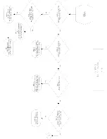
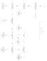
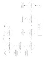
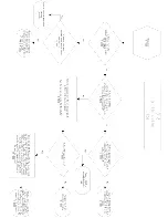
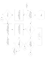
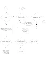
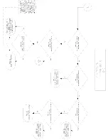
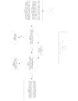
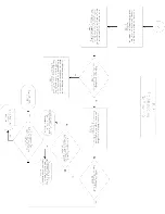
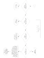
5.  Service Modes, Error Codes and Faultfinding


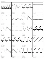
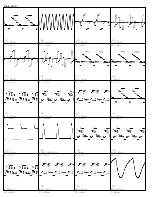
6.  Block Diagrams and Testpoints


7.  Electrical Diagrams and PWB's


     B8 CHASSIS TABLE OF SCHEMATIC DIAGRAMS


     MAIN CHASSIS (SECTION 1 OF 5)


     MAIN CHASSIS (SECTION 2 OF 5)


     MAIN CHASSIS (SECTION 3 OF 5)


     MAIN CHASSIS (SECTION 4 OF 5)


     MAIN CHASSIS (SECTION 5 OF 5 )


     CRT PANEL (13", 19", & 20")


     CRT PANEL (25" & 27")


     KEYBOARD/SOUND SHAPER PANEL


     STEREO PANEL SCHEMATIC


     OCV TV PANEL SCHEMATIC


     CARD INTERCONNECT PANEL


     HEALTH CARE JACK PANEL


     LODGING/SMART PORT PANEL


     MAIN CHASSIS PCB (TOP)


     MAIN CHASSIS PCB (BOTTOM)


     13", 19", & 20" CRT PANEL PCB


     25", & 27" CRT PANEL PCB


     KEYBOARD/SOUND SHAPER PCB


     STEREO PANEL PCB


     OCV TV PANEL PCB (TOP)


     OCV TV PANEL PCB (BOTTOM)


     CARD INTERCONNECT PANEL PCB


     HEALTH CARE JACK PANEL PCB


     LODGING/SMART PORT PANEL PCB


8.  Adjustments


10.  Spare Parts List


  Copyright 2001 Philips Consumer Electronics B.V. Eindhoven, The Netherlands.

All rights reserved.  No part of this publication may be reproduced, stored in a
retrieval system or transmitted, in any form or by means, electronic, mechanical,
photographic, or otherwise without the prior permission of Philips.

©

Published by Philips Consumer Electronics

Subject to modification

2005 Aug 24

Summary of Contents for B8 Series

Page 1: ...ALTH CARE JACK PANEL LODGING SMART PORT PANEL MAIN CHASSIS PCB TOP MAIN CHASSIS PCB BOTTOM 13 19 20 CRT PANEL PCB 25 27 CRT PANEL PCB KEYBOARD SOUND SHAPER PCB STEREO PANEL PCB OCV TV PANEL PCB TOP OCV TV PANEL PCB BOTTOM CARD INTERCONNECT PANEL PCB HEALTH CARE JACK PANEL PCB LODGING SMART PORT PANEL PCB 8 Adjustments 10 Spare Parts List Copyright 2001 Philips Consumer Electronics B V Eindhoven Th...

Page 2: ......

Page 3: ......

Page 4: ......

Page 5: ......

Page 6: ......

Page 7: ......

Page 8: ......

Page 9: ......

Page 10: ......

Page 11: ......

Page 12: ...20 uSec 6 50 Vp p 5 mSec 7 800 mVp p 5 mSec 8 2 7 Vp p 5 mSec 9 400 mVp p 5 mSec 10 29 Vp p 5 mSec 11 1 5 Vp p 5 mSec 12 2 2 Vp p 20 uSec 13 2 2 Vp p 20 uSec 14 2 2 Vp p 20 uSec 15 3 5 Vp p 20 uSec 16 3 6 Vp p 5 mSec 17 450 mVp p 5 mSec 18 750 mVp p 5 mSec 19 5 Vp p 20 uSec 20 4 2 Vp p 20 uSec ...

Page 13: ... 20 uSec 26 1 4 Vp p 20 uSec 27 2 5 Vp p 20 uSec 28 1 Vp p 20 uSec 29 1 4 Vp p 20 uSec 30 2 5 Vp p 20 uSec 31 2 5 Vp p 20 uSec 32 1 6 Vp p 20 uSec 33 120 Vp p 20 uSec 34 1040 Vp p a 20 uSec 35 1 Vp p 20 uSec 36 1 8 Vp p 20 uSec 37 2 Vp p 20 uSec 38 110 Vp p 20 uSec 39 110 Vp p 20 uSec 40 850 mVp p 5 mSec ...

Page 14: ...20B8 7562 41 110 Vp p 20 uSec ...

Page 15: ...trol Settings Mode Switches and Service Factory Setup Data The chassis features a Very Large Scale Integration VLSI IC for TV signal processing This IC performs Video IF Sound IF AGC control Horizontal Signal processing Vertical Signal processing Horizontal Vertical synchronization and Chrominance Luminance processing The On Screen Graphics information is placed on the main signal within the TV Si...

Page 16: ...d applied to the Audio Amp Output IC IC730 to drive the speakers For the stereo equipped sets the detected baseband audio signal exits IC271 Pin 15 and then enters the Stereo Decoder IC200 The Stereo Decoder has Internal External switching via the control input on Pin 21 to allow either the detected baseband audio or External Audio from another source to be routed through and exit to IC730 and IC7...

Page 17: ...t The horizontal signal is applied to a Horizontal Driver Q502 where the signal is amplified and transformer coupled to the Horizontal Output transistor Q503 The output from Q503 drives the Integrated Flyback Transformer The IFT develops the High Voltage Screen Voltage Focus Voltage and Filament Voltage for the Picture Tube If the voltage in T501 T502 for 25 and 27 inch sets goes high a sample is ...

Page 18: ...ing Regulator IC starts switching when the initial voltage is applied through the Start circuit The Switching Regulator and the Drive circuits turns the Switch On and Off to allow current flow through the primary of transformer T425 Energy stored in the primary during the On time is delivered to the secondaries during the Off time Feedback from the Hot secondary is used to control the Switching Re...

Page 19: ...All Models 7562 MAIN CHASSIS SECTION 1 OF 5 ...

Page 20: ...All Models 7562 MAIN CHASSIS SECTION 2 OF 5 ...

Page 21: ...All Models 7562 MAIN CHASSIS SECTION 3 OF 5 ...

Page 22: ...All Models 7562 MAIN CHASSIS SECTION 4 OF 5 ...

Page 23: ...All Models 7562 MAIN CHASSIS SECTION 5 OF 5 ...

Page 24: ...All Models 7562 CRT PANEL 13 19 20 ...

Page 25: ...All Models 7562 CRT PANEL 25 27 ...

Page 26: ...All Models 7562 KEYBOARD SOUND SHAPER PANEL ...

Page 27: ...All Models 7562 STEREO PANEL SCHEMATIC ...

Page 28: ...All Models 7562 OCV TV PANEL SCHEMATIC ...

Page 29: ...All Models 7562 CARD INTERCONNECT PANEL ...

Page 30: ...All Models 7562 HEALTH CARE JACK PANEL ...

Page 31: ...All Models 7562 LODGING SMART PORT PANEL ...

Page 32: ...All Models 7562 MAIN CHASSIS PCB TOP ...

Page 33: ...All Models 7562 MAIN CHASSIS PCB BOTTOM ...

Page 34: ...All Models 7562 13 19 20 CRT PANEL PCB ...

Page 35: ...All Models 7562 25 27 CRT PANEL PCB ...

Page 36: ...All Models 7562 KEYBOARD SOUND SHAPER PCB ...

Page 37: ...All Models 7562 STEREO PANEL PCB ...

Page 38: ...All Models 7562 OCV TV PANEL PCB TOP ...

Page 39: ...All Models 7562 OCV TV PANEL PCB BOTTOM ...

Page 40: ...All Models 7562 CARD INTERCONNECT PANEL PCB ...

Page 41: ...All Models 7562 HEALTH CARE JACK PANEL PCB ...

Page 42: ...All Models 7562 LODGING SMART PORT PANEL PCB ...

Page 43: ...djustments are made through software intervention The remote transmitter supplied with the set may be used in order to modify register values stored within the EEPROM IC on the Main Chassis Board Assembly The G96SVC Service Remote is an ideal tool for this purpose Order 4835 219 17656 Refer to the SERVICE MODE covered later 3 Refer to the Component Location Diagram Figure 1 for a quick location of...

Page 44: ...back Transformer to obtain 120Vp p Screen Control G2 Setup 25 27 1 Apply an NTSC Color Bar test pattern with the color off to the antenna input of the TV Receiver 2 Select the active channel 3 Set all the customer picture controls to mid range 4 Using an oscilloscope measure and note the peak to peak voltage of the CRT Cathodes Use the legs of R60 R61 and R62 which tie to the CRT socket 5 Using th...

Page 45: ...rm Degauss Procedure first 1 Place the multi pole Purity and Convergence Assembly with the 2 Y pole Purity Rings directly in the gap between the G2 and G3 Focus Grids As shown in Figure 2 2 Connect a Center Cross or Crosshatch pattern to the Antenna terminals 3 Enter Service Page G White Balance Set the Green control to minimum 4 Loosen the Yoke Clamp screws pull the Yoke back and remove the three...

Page 46: ...er to set the value to its minimum 00 8 Slowly spread the 2 X Pole Purity Rings to center the Green portion of the screen leaving the same amount of Red on the right side as there is Blue on the left 9 Loosen the Yoke Clamp screws and slide the Yoke back to the point of best Green Purity 10 Tighten the Yoke Clamp screw slightly so that the Yoke can still be moved with some friction 11 Proceed to S...

Page 47: ...ynamic Edge Convergence Review Pre Convergence Information Note Three rubber wedges are used to secure the correct position of the Deflection Yoke They are to ultimately be placed as shown in figure C or F of this display 1 Apply a crosshatch pattern signal to the antenna input 2 Use Service Page G to set the green control to minimum 3 Tilt the Yoke Up and Down to converge the Red and Blue vertica...

Page 48: ...19 17656 The service mode makes it possible to change the values of special memory registers in the EEPROM IC IC302 These registers affect the customer adjustments and other functions These registers also make many other service adjustments possible that previously would have been handled by conventional controls mounted on the P C Board Service Mode Entry and Exit Using the remote transmitter ent...

Page 49: ...y a special display Service Mode Display The first letter on the top line is an S This letter indicates that the set is in the Service Mode The second letter indicates which Service Page the set is currently in The number showing at the top right corner of the display is the currently tuned channel The number shown in the upper middle of the display 31350100661 is the current level of software in ...

Page 50: ...381 0 01pF 50V 10 Ceramic 4835 122 87024 C383 1uF 50V 20 Electrolytic 4835 121 47406 C384 470pF 50V 10 Ceramic 4835 122 47614 C390 100pF 5 50V Carbon Certain Models only 4835 122 87012 C391 100pF 5 50V Carbon Certain Models only 4835 122 87012 C392 100pF 5 50V Carbon Certain Models only 4835 122 87012 S C400 0 220uF 250V Mylar 4835 121 47597 C401 2200pF 250VAC Ceramic All 19 w SVH S 20 25 27 Latam...

Page 51: ...ctrolytic Certa in Models only 4835 121 47586 C744 2200pF 50V 10 Ceramic Certain Mod els only 4835 122 87544 C745 0 47uF 100V Polyester Certain Model s only 4835 121 47222 C746 2200pF 50V 10 Ceramic Certain Mod els only 4835 122 87544 C747 0 033uF 10 50V Electrolytic Certa in Models only 4835 121 47587 C748 2200pF 50V 10 Ceramic Certain Mod els only 4835 122 87544 C770 1000uF 25V Electrolytic 4835...

Page 52: ...23 R390 100 ohm 5 1 2W Metal Film Certain Models only 4835 116 57684 R391 100 ohm 5 1 2W Metal Film Certain Models only 4835 116 57684 R392 100 ohm 5 1 2W Metal Film Certain Models only 4835 116 57684 R393 100k 5 1 2W Metal Film Certain Mod els only 4835 116 57687 R400 4 7 ohm 5 1 2W Metal Film 4835 116 57009 S R401 4 7 ohm 5 1 2W Metal Film 4835 116 57009 R402 1 5 ohm 5 10W Wire 4835 112 37029 R4...

Page 53: ...ly 4822 051 10102 R735 3 3k 5 1 2W Metal Film Certain Mod els only 4835 116 57714 R736 3 3k 5 1 10W Metal Film Certain Mo dels only 4835 111 37247 R737 100 ohm 5 1 10W Metal Film Certain Models only 4835 111 37432 R738 100 ohm 5 1 10W Metal Film Certain Models only 4835 111 37432 R739 22k 5 1 2W Metal Film Certain Mode ls only 4835 116 57706 S R740 10 ohm 5 1 3W Metal Film Certain M odels only 482...

Page 54: ...in Models o nly 4835 130 37059 D450 Diode Silicon BYM36C 4835 130 37773 D460 Diode Silicon BYD33J 4835 130 37094 D508 Diode Silicon BAS216 4835 130 37905 D509 Diode Silicon 1N4148 4835 130 37048 D511 Diode Silicon BYV95C 4835 130 37052 S D530 Diode Silicon BAS216 4835 130 37905 D550 Diode Silicon BYD33J 4835 130 37094 D563 Diode Silicon 1N4148 4835 130 37048 D571 Diode Silicon BYD33J 4835 130 3709...

Page 55: ...5 265 97422 K405 Relay 12V G5P1A B 4835 280 47043 S379 Key Switch 4835 276 57004 SH271 BiMos Shield 3135 011 00630 SH345 Micro Shield 3135 011 00640 00APT186 CRT PANEL CAPACITORS C2 470pF 10 500V Ceramic 4835 122 47211 C3 47pF 5 50V Ceramic 4835 122 47608 C4 1000pF 10 500V Ceramic 4835 122 47384 C5 470pF 10 500V Ceramic 4835 122 47211 C6 470pF 10 500V Ceramic 4835 122 47211 C7 0 1uF 250V Polyester...

Page 56: ...20 Electrolytic 4835 124 47503 2164 10uF 20 50V Electrolytic 4835 124 47499 2171 0 100uF 63V Polyester 4835 121 47602 2172 220uF 25V Electrolytic 4835 124 47557 2106 2 2uF 50V Electrolytic ASD038 041 only 4835 124 47502 2126 2 2uF 50V Electrolytic ASD038 041 only 4835 124 47502 2165 0 0027uF 50V 10 Ceramic ASD038 on ly 4835 122 37024 2166 0 0027uF 50V 10 Ceramic ASD038 044 only 4835 122 37024 RESI...

Page 57: ... 1 4W Metal Film 4835 111 37023 R3 4 7k 5 1 4W Metal Film 4835 111 37037 R4 4 7k 5 1 4W Metal Film 4835 111 37037 R5 47 ohm 5 1 4W Metal Film 4835 111 37107 R6 4 7k 5 1 4W Metal Film 4835 111 37037 R7 4 7k 5 1 4W Metal Film 4835 111 37037 R8 4 7k 5 1 4W Metal Film 4835 111 37037 R9 10k 5 1 4W Metal Film 4835 111 37023 R10 47k 5 1 4W Metal Film 4835 111 37038 R11 47 ohm 5 1 4W Metal Film 4835 111 3...

Page 58: ...64 only 3104 308 71770 J604 5 Pin Connector 2422 025 14672 J605 6 Pin Connector 2422 025 14673 J606 Phone Jack RJ6 0018 221 20006 00A10630 CARD INTERCONNECT CAPACITORS C700 220uF 25V Electrolytic 4835 124 47557 C702 220uF 25V Electrolytic 4835 124 47557 RESISTORS R700 1 ohm 5 1W Metal Film 4835 116 57117 R702 75 ohm 5 1 8W Carbon Film 4835 110 67147 R703 1 ohm 5 1W Metal Film 4835 116 57117 R704 4...

Reviews: