


VIDEO
S-VIDEO
L
Pb
Pr
VIDEO
S-VIDEO
L
AUDIO
L
R
AUDIO
L
R
G/Y
R/Pr
B/Pb
V
H
SYNC
L
R
AUDIO
L
R
AUDIO
HD INPUT-AV 4
HD INPUT-AV 5
INPUT-AV 2
OUTPUT
INPUT-AV 1
Y
ANTENNA IN 75
Ω
DVI
2
TO TV
CABLE
IN
OUTPUT
CH
3 4
1
3
Back of TV
Back of Cable Box
(example only)
Cable TV
Signal
3135 035 21372
Rear-projection
HDTV Monitor
Rear-projection
HDTV Monitor
Quick Use and Setup Guide
Quick Use and Setup Guide
H
OOKING UP THE
TV
C
ONTENTS
Important Notice/Warning............................................................1
Hooking up the TV ..................................................................1–2
Operating the Television and Remote Control ........................2–4
Using the Installation Features ................................................4–6
Using the Picture-in-Picture (PIP) Feature ..................................7
Adjusting the Manual Converge Controls....................................8
IMPORTANT
This owner's manual is used with several different television models.
Not all features (and drawings) discussed in this manual will neces-
sarily match those found with your television set. This is normal and
does not require that you contact your dealer or request service.
B
EST
V
IEWING
T
he major benefit of this projection television is its large view-
ing screen. To see this large screen at its best, test various
locations in the room to find the optimal spot for viewing.
NOTE: Be sure to allow a free flow of air to and from the per-
forated back cover of the set.
To avoid cabinet warping, cabinet color changes,
and increased chance of set failure, do not place
the TV where temperatures can become excessively
hot—for example, in direct sunlight or near a
heating appliance.
Magnetic fields, such as those of external speak-
ers, may cause the picture to distort if the speak-
ers are placed too close to the television. Move
the magnetic field source away from the TV until
there is no picture distortion.
As an Energy Star®
Partner, Philips Consumer
Electronics has determined
this product meets the Energy
Star® guidelines for energy
efficiency. Energy Star® is a
U.S. registered mark. Using
products with the Energy
Star® label can save energy.
Saving energy reduces air pol-
lution and lowers utility bills.
WARNING: TO PREVENT FIRE OR SHOCK HAZARD DO NOT
EXPOSE THIS UNIT TO RAIN OR EXCESSIVE MOISTURE.
VIDEO
S-VIDEO
L
Pb
Pr
VIDEO
S-VIDEO
L
AUDIO
L
R
AUDIO
L
R
G/Y
R/Pr
B/Pb
V
H
SYNC
L
R
AUDIO
L
R
AUDIO
HD INPUT-AV 4
HD INPUT-AV 5
INPUT-AV 2
OUTPUT
INPUT-AV 1
Y
ANTENNA IN 75
Ω
DVI
1
VIDEO
S-VIDEO
L
Pb
Pr
VIDEO
S-VIDEO
L
AUDIO
L
R
AUDIO
L
R
G/Y
R/Pr
B/Pb
V
H
SYNC
L
R
AUDIO
L
R
AUDIO
HD INPUT-AV 4
HD INPUT-AV 5
INPUT-AV 2
OUTPUT
INPUT-AV 1
Y
ANTENNA IN 75
Ω
DVI
C
ABLE
TV
C
ABLE
B
OX WITH
RF IN/OUT
C
ABLE
B
OX WITH
A/V O
UTPUTS
Cable TV
Signal
Back of TV
VIDEO
S-VIDEO
L
Pb
Pr
VIDEO
S-VIDEO
L
AUDIO
L
R
AUDIO
L
R
G/Y
R/Pr
B/Pb
V
H
SYNC
L
R
AUDIO
L
R
AUDIO
HD INPUT-AV 4
HD INPUT-AV 5
INPUT-AV 2
OUTPUT
INPUT-AV 1
Y
ANTENNA IN 75
Ω
DVI
CABLE
IN
TO
TV
VIDEO
OUT
L
R
AUDIO
OUT
3 4
OUTPUT
CH
4
3
PIP ON/OFF
2
1
3
5
4
6
8
7
9
0
TV
SWAP
PIP CH
DN
UP
ACTIVE
CONTROL FREEZE
SOUND
MUTE
SURF
A/CH
PICTURE
STATUS/
EXIT
SURF
ITR/
RECORD
HOME
VIDEO
HOME
MOVIES
PERSONAL
SLEEP
REC •
PIP
POSITION
VCR
ACC
MENU/
SELECT
VOL
CH
TV/VCR
FORMAT
SAP
PROG.LIST
DOLBY V
AV
5
1
2
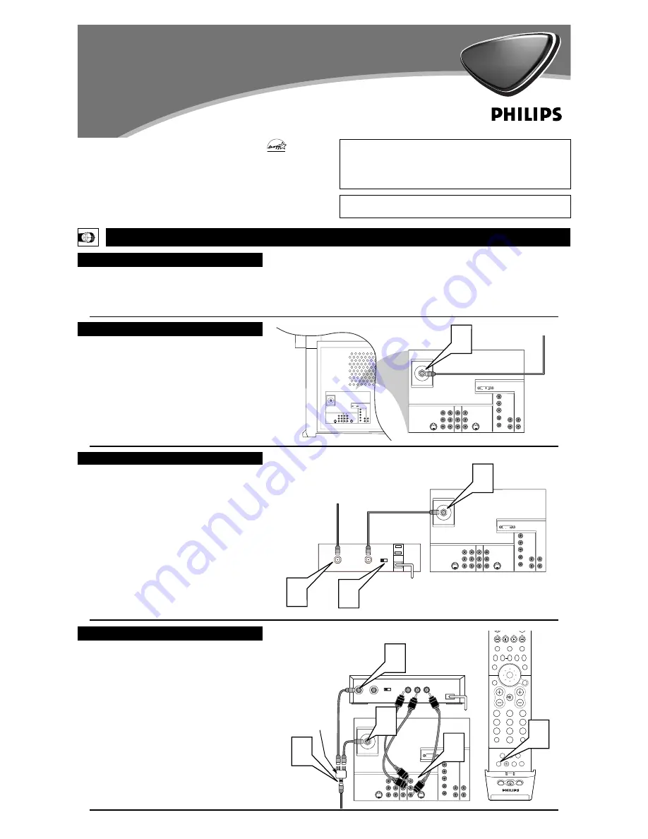
Cable TV Signal
T
his connection WILL supply Stereo sound to the TV.
1
Connect the cable TV signal to the ANTENNA IN 75
Ω
jack on the back of the TV.
NOTE:
Refer to the sections on TUNER MODE and AUTO
PROGRAM on pages 4 and 5 of this guide. Set TUNER
MODE to the CABLE option. Run AUTO PROGRAM to
store all available cable channels in the TV’s memory.
T
his is for example purposes only. The back of your cable box
may be labeled somewhat differently.
This connection WILL NOT supply stereo sound to the TV.
1
Connect the cable TV signal to the CABLE IN jack on
the back of the cable box.
2
Connect a coaxial cable (not supplied) to the TO TV
jack on the back of the cable box and to the ANTENNA
IN 75
Ω
jack on the back of the TV.
3
Be sure to set the Output Channel switch on the back of
the cable box to CH 3 or 4, then tune the cable box on
the TV to the corresponding channel. Once tuned,
change channels at the cable box, not the TV.
NOTE:
Refer to the sections on TUNER MODE and AUTO
PROGRAM on pages 4 and 5 of this guide. Set TUNER
MODE to the CABLE option. Run AUTO PROGRAM to
store all available cable channels in the TV’s memory.
Back of TV
Back of Cable Box
(example only)
T
his is for example purposes only. The back of your cable box
may be labeled somewhat differently.
This connection MIGHT supply stereo sound to the TV. Check
with your cable TV company.
1
Connect the incoming cable TV signal to a signal splitter.
2
Connect a coaxial cable to a connector on the signal split-
ter and to the ANTENNA IN 75
Ω
jack on the back of the
TV.
3
Connect a coaxial cable to a connector
o
n the signal split-
ter and to the CABLE IN jack on the back of the cable
box.
4
Connect A/V cables to the VIDEO and AUDIO L and R
outputs on the back of the cable box and to the AV2
VIDEO and corresponding AUDIO L and R jacks on the
back of the TV.
5
To view programs from your cable box, plug in the TV,
turn it on, and then press the AV button on the remote
control as many times as necessary to select the AV2
input source.
Signal
Splitter


