Published by CQZ/SC 1610 Quality
Printed in the Netherlands
Subject to modification
©
TP Vision Netherlands B.V.
All rights reserved. Specifications are subject to change without notice. Trademarks are the
property of Koninklijke Philips Electronics N.V. or their respective owners.
TP Vision Netherlands B.V. reserves the right to change products at any time without being obliged to adjust
earlier supplies accordingly.
PHILIPS and the PHILIPS’ Shield Emblem are used under license from Koninklijke Philips Electronics N.V.
Colour Television
Chassis
TPN16.1E
LA
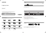
Contents
Page
Contents
Page
Technical Specs, Diversity, and Connections
Precautions, Notes, and Abbreviation List
Cable dressing (24" 5211 series)
Service Modes, Error Codes, and Fault Finding 14
10. Circuit Diagrams and PWB Layouts
Drawing PWB