


● Thank you for your purchase of Panasonic welding power source.
● Before operating this product, please read the instructions carefully and save this manual
for future use.First of all, please read “Safety precautions” or “Safety manual”.
● SPEC. No.
:
YW-50DNW1HAG
Panasonic Welding Systems (Tangshan) Co., Ltd.
WTW031TE0PAA01
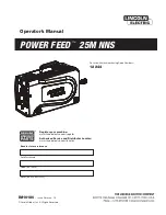
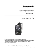
Wire Feeder
Model No.
YW-50DNW
Operating Instructions
Summary of Contents for YW-50DNW
Page 14: ...9 9 Overall dimensions ...
Page 15: ...10 10 Circuit diagram PCB ...
Page 16: ...11 11 Parts layout drawing ...
Page 18: ...13 12 Parts List ...