background image

● Thank you for your purchase of Panasonic welding power source.

● Before operating this product, please read the instructions carefully and save this

manual for future use. First of all, please read “Safety precautions” or “Safety

manual”.

● SPEC. No.

YD-500KR2HJG

Panasonic Welding Systems (Tangshan) Co., Ltd.

Model No.

YD-200KR

YD-350KR

YD-500KR

Operating Instructions

Thyristor Controlled MIG/MAG Arc Welding Power Source

TSM80227-05

Summary of Contents for YD-200KR

Page 1: ...e instructions carefully and save this manual for future use First of all please read Safety precautions or Safety manual SPEC No YD 500KR2HJG Panasonic Welding Systems Tangshan Co Ltd Model No YD 200KR YD 350KR YD 500KR Operating Instructions Thyristor Controlled MIG MAG Arc Welding Power Source TSM80227 05 ...

Page 2: ...er Control Disabled 16 DUTY CYCLE 17 APPLICATIONS E X T E N D E D F U N C T I O N S 1 8 C o n n e c t i n g t h e E x t e n s i o n C a b l e 1 8 Sw itches and Controls on the Printed Circuit Board 19 Setting the Selector Switches On the Printed Circuit Board 20 Adjusting the Controls on the Printed Circuit Board 23 S w i t c h i n g t h e D C R e a c t o r T a p 2 3 FOR YOUR INFORMATION D A I L Y...

Page 3: ...Burn Out of Equipment or Fire Prevent a Fire or Burn out of the Equipment due to Overheat Install a welding power unit 20 cm or more away from the wall and 50 cm or more from an inflammable substance Prevent a Fire or Burn out of the Equipment due to Spark See to it that spark spatter flash will never reach an Inflammable substance or fall on the equipment and enter inside through an air Inlet or ...

Page 4: ... brought as is into the EU after January 1 1995 The same restriction also applies to any country which has signed the EEA accord Please be absolutely sure to consult with us before attempting to relocate or resell this product to or in any EU member state or any other country which has signed the EEA accord ACCESSORIES We1ding power source Name Code No Q ty Glass tube fuse 1A 61NR010H 1 Glass tube...

Page 5: ... Phase 440V 3 Phase 415V Frequency 50 60Hz Switchable on the printed circuit board Facility capacity Commercial power source 20kVA Engine generator Twice large than 18 1 kVA with compensating winding Primary line current Approx 47 5A Approx 27 5A Approx 23A Approx 25 2A Cable sectional area Welding source input side 14mm 2 or more 8mm 2 or more 8mm 2 or more 8mm 2 or more Welding source output sid...

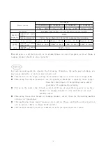
Page 6: ...safe use and operation observe the following Otherwise the parts may he broken arc may become unstable or devices may be burnt out Fluctuation of the supply voltage An allowable range is a rated input voltage 10 When using the engine generator use the generator which has a capacity twice larger than the rated input of the welding source and is provided with compensating winding Wiring on the input...

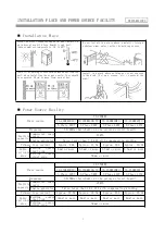
Page 7: ...ared by the customer The non crosshatched units may be altered according to a customer s request or separately arranged PREPARATIONS Welding Torch Switch box 3 phase rated Input Voltage Gas Regulator Grounding Input Cable Heater Cable Gas Hose Gas Bomb Grounding Wire Feed Control Cable Output Cable Base Metal Cable Base Metal Welding Wire Wire Feeder Grounding ...

Page 8: ...nce on the cable or bring it into contact with a weld Zone Tighten securely a cable joint This machine has input power frequency select switch Please confirm the correct position of the switch Refer to pages 22 23 and 25 When a frequency changes depending on where you use the welding source switch to an adequate frequency PREPARATIONS Safety Warning Loose the left and right screws to remove the co...

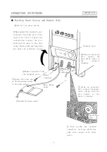
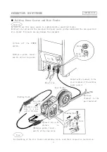
Page 9: ...back the terminal cover Remove two bolts from the terminal cover Connect the other end of the base metal cable to the base metal Minus terminal Plus terminal Base Metal Cable Using an accessory bolt connect the base metal cable to the minus terminal Using an accessory bolt connect the output cable coming from the wire feeder to the plus terminal Tape around any exposed conductive sections which ma...

Page 10: ... feeder and welding torch read their respective instruction manual Turn off the POWER switch Align the guide Guide Align a guide insert and fix with a ring screw Ring Screw Wire Feeder Output cable connect to the plus terminal of the welding power source Gas hose Connect to the gas regulator Connect a gas hose to a gas outlet fitting Gas outlet fitting Welding Torch Locking Bolt CC Fixture Confirm...

Page 11: ... of the following In case of CO2 welding use carbon dioxide gas with moisture content of 0 005 or less or welding carbon dioxide gas For a mixed gas in case of MAG welding use MAG welding gas argon gas with 5 to 20 carbon dioxide gas When mixing two kinds of gas carbon dioxide gas and argon gas for use use a gas mixer In order to avoid irregular mixture Argon gas to be mixed should be high purity ...

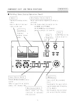
Page 12: ...as wire diameter choices of 1 2 l 4 and 1 6 Fuse A power fuse for the control circuit is Fuse A feeder motor fuse Voltmeter Indicates a welding voltage value Crater Selector Switch POWER Switch Wire Selector Switch Selects whether to enable crater control Refer to pages 18 19 and 43 enable ON disable OFF Select either the flux cored wire in conformity with your wire Turns on off this equipment Not...

Page 13: ...r voltage may not be an optimum condition depending on a welding posture wire brand and length of an extension cable If this is the case the crater voltage can be finely adjusted lower by turning this control to the left and higher by turning to the right Gas Supply Switch Warn Indicator Lamp Power Indicator Lamp Prior to welding use this switch to adjust a gas flow rate in advance Set it to the C...

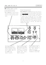
Page 14: ...wound in Scale Plate Fixing Bolt Capable of adjusting a welding current value Note When SIMPLE UNIFIED is selected the welding voltage is internally processed so that it automatically assumes an appropriate value with respect to a set current value This is called simple unification Welding Current Control Capable of adjusting a welding voltage Note When SIMPLE UNIFIED is selected refer to page 25 ...

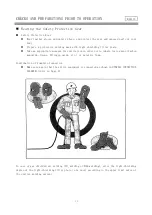
Page 15: ...e measure for ventilation in order not to inhale toxic gases Carbon monoxide Ozone Nitrogen oxide etc or metallic fume Confirmation of Complete Connection Make sure again that the entire equipment is connected as shown in OVERALL CONNECTION DIAGRAM refer to Page 6 In case of gas shielded arc welding CO2 welding or MAG welding alter the light shielding degree of the light shielding filter plate to ...

Page 16: ...witch box Turn on the POWER switch Welding Power Source Flow Meter Gas Regulator Primary Pressure Gauge Open the main valve of the gas bomb Prior to opening it make sure that a flow rate control knob is turned to the SHUT side Turn the flow rate control knob gradually toward OPEN so that a flow meter indicates a required value Flow Rate Control Knob Gas Bomb Earthing Terminal BASICS ...

Page 17: ...e w e l d i n g w i r e Wire Correction Roller Lock nut Correction Adjusting Bolt CC Fixture Wire Stopper Hole Feed Roller Knob Screw Spool Clamping Washer Wire Correction Roller Loosen a knob screw to remove a spool clamping washer Attach the welding wire to the spool fitting In the clockwise direction of the wire spool Put back the spool clamping washer and tighten the knob screw Remove a wire s...

Page 18: ... be taken when adjusting the wire pressurization force For your safety be sure to turn off the switch of the switch box located on the input side of the welding power source switch with fuse or no fuse breaker or leakage breaker and POWER switch of the welding power source At the time of inching do not peep through a tip hole to check if the wire is being fed It is very dangerous because the wire ...

Page 19: ...ter treatment If arc discontinues for 0 5 second or more during welding however self hold will be cancelled BASICS The following two kinds of welding are allowed by operating the CRATER ON OFF selector switch on the operation panel and the torch switch Be sure to read Duty cycle on Page 20 and observe a duty cycle in using the equipment Using only this switch allows you to start stop operation CRA...

Page 20: ... Operation Procedure Set the CRATER ON OFF selector switch to OFF and turn on off the torch switch Synchronized with it welding arc starts or stops Operation Timing Chart BASICS Welding Arc Start Welding Arc Stop Torch Switch ON Torch Switch OFF Torch Switch Gas Supply Wire Feed Welding Voltage Welding Current Welding Condition Adjustment Tpf Gas preflow time Arc start timing Arc stop timing ...

Page 21: ...welding current and duty cycle for the YD 200KR2 350KR2 500KR2 welding current value and use the equipment within that range When using in combination with other device such as welding torch etc use at the lowest duty cycle reactor of each device BASICS Welding Current A Duty cycle Duty cycle Duty cycle 100 50 0 50 100 200 300 Welding Current A YD 200KR Service Range YD 350KR Service Range YD 500K...

Page 22: ...ce or the connected extension cable or how it is led about Undesirable effects are magnified as the extension cable becomes 1onger or its sectional area becomes smaller Therefore erroneous selection of the extension cable used may degrade a welding result Upon using the extension cable bear the following in mind Relations between the extended distance and cable s sectional area Extended distance o...

Page 23: ...ntrols on the printed circuit board as well which are available for extending many different functions Caution After switching work is completed be sure to put back the front panel as it was If this is neglected dust may accumulate inside any destroy the electric circuit of the printed circuit board Change over the switches on the printed circuit board Put back the front panel with 4 bolts 1 Turn ...

Page 24: ...be set to ON The relations with the crosshatched new control sequence operation and welding torch switch operation in the table below are described in the timing chart on the next page Setting of CRATER ON OFF Switch Selector Switch 8 6 on PCB Control Sequence Operation Time Chart DISABLE OFF Torch Switch Synchronous Operation Refer to Page 19 DISABLE ON Switch 8 selected General self hold crater ...

Page 25: ...condition Operation Timing chart Tpf Gas preflow time Arc start timing Arc stop timing An initial condition welding period refers to a period between arc generation by Initial torch switch on and first torch switch off A regular welding period refers to a period between first torch switch off and next torch switch on A crater welding period refers to a period between 2nd torch switch on and next t...

Page 26: ...ng to INDIVIDUAL allows optional setting of the welding voltage to widen an adjustment width Selector Switch 11 FTT Control Enable Disable Set to DISABLE upon shipment DISABLE Does not provide FTT control ENABLE Provides FTT control Refer to page 44 enable ON disable OFF Selector Switch 12 60Hz 50Hz 60Hz Select 60 Hz when using in a 60 Hz district 50 Hz Select 50 Hz when using in a 50 Hz district ...

Page 27: ...nt position Preflow time Adjusts the Preflow time VR11 Preflow time Decrease Increase 0 05s 0 6s Adjustment position Afterflow time Adjusts the Afterflow time VR12 Afterflow time Decrease Increase 0 35s 0 9s Adjustment position Exterior ammeter Adjustment Adjusts the Exterior ammeter VR15 Decrease Increase Center position Already adjusted Do not touch VR3 VR4 VR6 VR7 VR9 Adjustment position Switch...

Page 28: ...s required For replacement parts be sure to use those purely designed for the PANASONIC welding machines in order to maintain performance and functionality Welding power source Block Inspection point Remarks Operation panel Sense of operating changing over the switches loose mounting Secure lighting up off of the POWER indicator lamp Cooling fan Smooth rotating sound and Generation of cooling wind...

Page 29: ...rry out inspection in an appropriate method suitable to your work site Roughly and simply in daily inspection Elaborately in details in periodic inspection Input cable Whether the input and output terminals of the input protective device of the switch box are tight Whether the fuse holder is clamped tight Whether the input terminal of the welding power source is clamped tight Whether the insulator...

Page 30: ...r source Using moisture free compressed air dry air blow off dust accumulated in the welding power source Removal of the top plate and side plates is shown on the following page Inspection of overall Welding Power Source and its Surroundings Centering around checks for odor discoloration trace of heat generation Loosened internal connections and retightening check the items which daily inspection ...

Page 31: ...ected to two output terminals Tie the two output terminals with a conductor to short circuit them 4 Using conductors tie between the anode and cathode of the thyristors SCR1 SCR6 to short circuit them The conductors used in and should have a sectional area of about 1 25 mm2 5 Remove the case grounding terminal wire number 9 The 200KR2 350KR2 has the case grounded using fasten terminals in two plac...

Page 32: ...w that phenomenon For the fuses the operation panel has a power fuse and the printed circuit board has a motor fuse and gas valve fuse respectively Welding Error Initial Diagnoses List Error Block and check item Switch box input protective device Turning on the switch securely Blown fuse Loose connection Input cable Cable being almost cut Loose connection Trace of overheat Switches on the welding ...

Page 33: ...power cable and torch switch contro1 cable Snapping of the cable bending fatigue Trace of a drop of a heavy substance Surface condition of the base metal and wire projection length Distance between the chip and base metal Oil contamination rust painting film Too much wire projection Output cable Insufficient sectional of area of cable Loose connection of the or output cable Improper power source t...

Page 34: ... the welding power unit When you restart welding be sure to lower the welding conditions shorten the welding time or lower the output current When the Warn indicator lamp goes on repeatedly stop using the machine It would lower insulation of internal parts or shorten their lives resulting in a trouble or burn out or the equipment never use the machine in a manner which may turn on the Warn Indicat...

Page 35: ...box turned on Is the switch of the switch box turned on Is the switch of the switch box turned on The printed circuit board is defective YES NO NO NO NO YES YES DC24V YES Is the electromagnetic contactor turned on The electromagnetic contactor is defective Is the output cable properly connected and the cable condition normal When the torch switch is turned on is the wire fed Is the output voltage ...

Page 36: ...ck NO NO When output cannot be adjusted When the torch switch is turned on does the voltmeter s needle swing Check the wire feeder for its connection Is it not snapped Is SIMPLE UNIFIED INDIVIDUAL properly selected Ask our office for examination repair When the torch switch is turned on does the voltmeter s needle swing Is the welding condition appropriated When it gets stuck to the chip decrease ...

Page 37: ...y or the human body such as electric shock or burn Caution After finding out a cause by following the flow chart take a remedy according to the relevant category below When the fuse is gone After eliminating a cause overload or short circuit replace the fuse with a specified one referring to the Parts List When the fuse goes again after turning on the power turn off the power and ask our office fo...

Page 38: ...ed a repair please contact our dealer where you purchased the equipment or our branch office When you ask for a repair let us know the following Your address name and phone number Machine type in terms of spec number Manufacture year and number inscribed on the name plate stuck to the welding power source Details of the trouble or error PREPARATIONS ...

Page 39: ...35 APART LAYOUT DRAWING The part specifications shown in figure is required to refer the attached parts list Front Right Side Rear Left Side YD KR2 200 350 25 ...

Page 40: ...36 AFTER SALE SERVICE The part specifications shown in figure is required to refer the attached parts list Front Right Side Rear Left Side YD 500KR2 25 ...

Page 41: ...meter KFM7BDC50VK 1 13 CT Cur transformer BLF400 S7 1 14 SW1 Switch LAY39 20X K2X 1 Power 15 SW2 Switch VLA04B1 2 1 Gas 16 SW3 Switch VLA04B1 2 1 Crater 17 SW4 Switch VLA04B1 2 1 Wire material 18 SW5 Switch ADS850CF1A02 1 Wire dia 19 VRAC Crater cur Adjustor TV18Y20FB502FNCB 1 20 VRVC Crater vol Adjustor TV18Y20FB502FNCB 1 21 LED1 Pilot lamp Green DB40BG 1 Power 22 LED2 Pilot lamp Red DB40BY 1 War...

Page 42: ...C400AK 1 12 V Volt meter KFM7BDC75VK 1 13 CT Cur transformer BLF400 S7 1 14 SW1 Switch LAY39 20X K2X 1 Power 15 SW2 Switch VLA04B1 2 1 Gas 16 SW3 Switch VLA04B1 2 1 Crater 17 SW4 Switch VLA04B1 2 1 Wire material 18 SW5 Switch ADS850CF1A02 1 Wire dia 19 VRAC Crater cur Adjustor TV18Y20FB502FNCB 1 20 VRVC Crater vol Adjustor TV18Y20FB502FNCB 1 21 LED1 Pilot lamp Green DB40BG 1 Power 22 LED2 Pilot la...

Page 43: ...er KFM7BDC600AK 1 12 V Volt meter KFM7BDC75VK 1 13 CT Cur transformer BLF400 S7 1 14 SW1 Switch LAY39 20X K2X 1 Power 15 SW2 Switch VLA04B1 2 1 Gas 16 SW3 Switch VLA04B1 2 1 Crater 17 SW4 Switch VLA04B1 2 1 Wire material 18 SW5 Switch ADS850CF1A02 1 Wire dia 19 VRAC Crater cur Adjustor TV18Y20FB502FNCB 1 20 VRVC Crater vol Adjustor TV18Y20FB502FNCB 1 21 LED1 Pilot lamp Green DB40BG 1 Power 22 LED2...

Page 44: ...CRCUIT DIAGRAM YD 200 350KR2 40 ...

Page 45: ...CIRCUIT DIAGRAM YD 500KR2 41 ...

Page 46: ...OUTSIDE DRAWING W D H YD 200KR2 376 675 747 YD 350KR2 376 675 747 YD 500KR2 436 675 762 42 ...

Page 47: ...bout 60 to 70 of the welding current so far regular welding current is a setting yardstick of the crater filler welding current Crater filler welding is generally referred to as crater welding There is a control sequence which allows you to switch the regular welding current so far to the lower crater welding current by operating the switch of the welding torch just before the end of welding work ...

Page 48: ...ct from the tip of the welding torch This causes the wire to get stuck to a weld assembly or worsens an arc start for next welding thus leading to an inconvenience To eliminate this inconvenience an output voltage is generated for a very short time to burn up surplus wire even after the torch switch is turned off This processing time is called a burn back time its time width differs depending on t...

Page 49: ...0 5 1 0 120 130 19 5 20 45 50 10 10 15 3 2 1 0 1 2 1 0 1 2 140 150 20 21 45 50 10 15 10 15 4 5 1 0 1 2 1 0 1 2 170 185 22 23 45 50 15 15 6 0 Front 1 2 1 2 1 5 230 260 24 26 45 50 15 15 20 Back 1 2 1 2 1 5 230 260 24 26 45 50 15 15 20 9 0 Front 1 2 1 2 1 5 320 340 32 34 45 50 15 15 20 Back 1 2 1 2 1 5 320 340 32 34 45 50 15 15 20 0 8 0 8 0 9 0 89 16 5 120 10 15 1 0 0 8 0 9 0 100 17 120 10 15 1 2 0 ...

Page 50: ...Phase 415V Frequency 50 60Hz Switchable on the printed circuit board Rated input 18 1kVA 16 1kW Rated output current DC 60 350A Rated output volt DC 16 36V Applicable wire dia for unitary control Solid wire mild steel 0 9 1 0 1 2mm flux cored mild steel 1 2mm Solid wire mild steel 0 8 1 0 1 2mm flux cored mild steel 1 2mm Rated duty cycle 50 Outside dimension W D H 376 675 747mm Mass 117kg Power s...

Page 51: ...Panasonic Welding Systems Tangshan Co Ltd Add Tangshan New Hi Tech Development Zone Hebei China TEL 86 0315 3206017 3206066 FAX 86 0315 3206070 3206018 POST CODE 063020 2017 09 ...

Reviews: