


Before operating this product, please read the instructions carefully and save this manual for future use.
Please also read the operating instructions of peripheral equipment.
First, please read the “Safety Precautions”.
English version is the original instructions.
2011
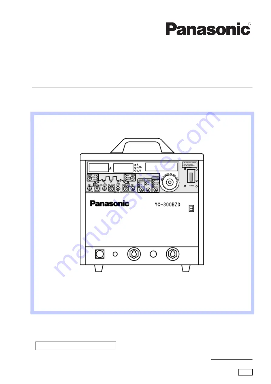
Operating Instructions
Model No.
YC-300BZ3YHD
Fully digital and inverter controlled TIG welding
OMCTT5621E18
DC TIG Welding Power Source


