


Before operating this product, please read the instructions carefully and save this manual for future use.
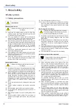
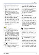
First of all, please read “Safety precautions” or “Safety manual.”
2011
Operating Instructions
Model No.
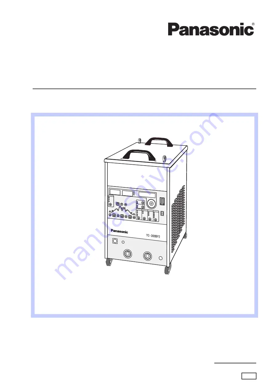
YC-300BP2YAF
Fully digital controlled power source
OMCTT5639E09
Inverter TIG welding power source
Summary of Contents for YC-300BP2YAF
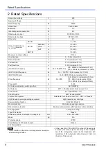
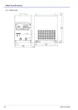
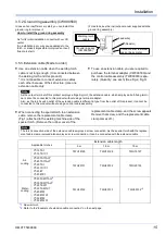
Page 10: ...Rated Specifications OMCTT5639E09 10 2 2 1 Dimensions ...
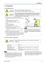
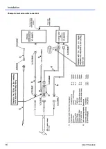
Page 16: ...Installation OMCTT5639E09 16 Example of extension cable connection ...
Page 49: ...Parts list OMCTT5639E09 49 9 Parts list ...
Page 52: ...OMCTT5639E09 52 ...
Page 53: ...Circuit diagram OMCTT5639E09 53 10 Circuit diagram NF9 NF8 ...
Page 54: ...Circuit diagram OMCTT5639E09 54 10 1 Enlarged left half NF8 MCB ...
Page 55: ...Circuit diagram OMCTT5639E09 55 10 2 Enlarged right half NF9 ...
Page 62: ...OMCTT5639E09 62 ...
Page 63: ...OMCTT5639E09 63 ...


