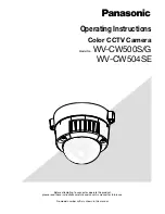
Panasonic WV-CW500S/G, Operating Instruction
The Panasonic WV-CW500S/G Operating Instruction manual is available for free download from manualshive.com. This comprehensive manual provides detailed instructions on how to operate and make the most of your Panasonic WV-CW500S/G product. Simplify your user experience by accessing the manual easily and conveniently at your fingertips.
Share
Download


Reviews:
No comments
Related manuals for WV-CW500S/G
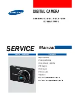
SAMSUNG ST77
Brand: Samsung Pages: 85
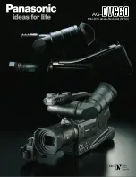
AGDVC60 - DIGITAL VIDEO CAMCORDER
Brand: Panasonic Pages: 8
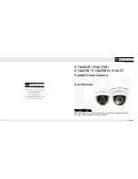
Infinity OMNI-Plus V1382TIRH
Brand: Digital Watchdog Pages: 19

WV-CW500S/G
Brand: Panasonic Pages: 32
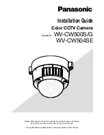
WV-CW504SE
Brand: Panasonic Pages: 44
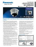
WV-NW502S
Brand: Panasonic Pages: 2
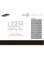
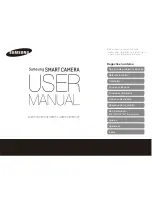
SMARTCAMERA WB150
Brand: Samsung Pages: 160
SMARTCAMERA WB150F
Brand: Samsung Pages: 159
ILCE-5000L
Brand: Sony Pages: 51
ILCE-5000L
Brand: Sony Pages: 181
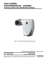
3960 Series
Brand: IVIEW Pages: 28
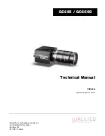
GC655
Brand: Allied Pages: 32

LIVE GAMER DUO
Brand: Avermedia Pages: 12
ST76
Brand: Samsung Pages: 132
TG-610
Brand: Olympus Pages: 4

SAMSUNG ST77
Brand: Samsung Pages: 132
DIVAR AN 5000
Brand: Bosch Pages: 56
DIVAR AN 5000
Brand: Bosch Pages: 170


