


Before attempting to connect or operate this product,
please read these instructions carefully and save this manual for future use.
No model number suffix is shown in this manual.
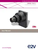
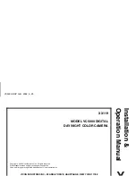
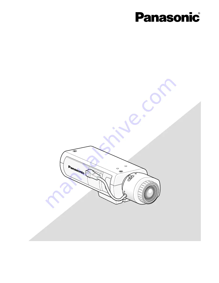
Operating Instructions
Color CCTV Camera
Model No.
WV-CP500
WV-CP504
This illustration represents WV-CP500.
Lens: Option