background image

© Panasonic Corporation 2012. 
Unauthorized copying and distribution is a violation 
of law.

ORDER NO.MTNC120204CE

B32 Canada: B61

47 inch Class 1080p LCD HDTV

Model No.

TC-L47ET5

LA35 Chassis

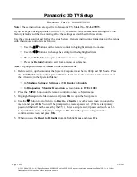
Summary of Contents for Viera TC-L47ET5

Page 1: ... Panasonic Corporation 2012 Unauthorized copying and distribution is a violation of law ORDER NO MTNC120204CE B32 Canada B61 47 inch Class 1080p LCD HDTV Model No TC L47ET5 LA35 Chassis ...

Page 2: ...de 11 6 4 Data Copy by SD Card 12 7 Troubleshooting Guide 15 7 1 Check of the IIC bus lines 15 7 2 Power LED Blinking timing chart 16 7 3 LCD Panel test mode 16 8 Disassembly and Assembly Instructions 17 8 1 Disassembly Flow Chart for the Unit 17 8 2 Disassembly Procedure for the Unit 17 9 Measurements and Adjustments 33 9 1 Voltage chart of P board 33 9 2 Voltage chart of A board 33 10 Block Diag...

Page 3: ...en the jumpered AC plug and each exposed metallic cabinet part on the equipment such as screwheads connectors control shafts etc When the exposed metallic part has a return path to the chassis the reading should be 100 Mohm and over When the exposed metal does not have a return path to the chassis the reading must be 1 1 2 Leakage Current Hot Check See Figure 1 1 Plug the AC cord directly into the...

Page 4: ... of the assembly 3 Use only a grounded tip soldering iron to solder or unsolder ES devices 4 Use only an anti static solder removal device Some solder removal devices not classified as anti static ESD protected can generate electrical charge sufficient to damage ES devices 5 Do not use freon propelled chemicals These can generate electrical charges sufficient to damage ES devices 6 Do not remove a...

Page 5: ...ee solder has a higher melting point than standard solder Typically the melting point is 50 70 F 30 40 C higher Please use a high temperature soldering iron and set it to 700 20 F 370 10 C Pb free solder will tend to splash when heated too high about 1100 F or 600 C If you must use Pb solder please completely remove all of the Pb free solder on the pins or solder area before applying Pb solder If ...

Page 6: ...6 3 Service Navigation 3 1 PCB Layout Board Name Function A Board Main K Board Remote Receiver LED Cat s eye P Board Power supply GK Board Power switch Control Button ...

Page 7: ... IN D SUB 15PIN VGA SVGA XGA WXGA SXGA DIGITAL AUDIO OUT PCM Dolby Digital Fiber Optic OTHERS SD CARD slot ETHERNET 10BASE T 100BASE TX Dimensions W H D Including pedestal 43 6 inch 28 1 inch 10 6 inch 1 107 mm 712 mm 268 mm TV Set only 43 6 inch 26 2 inch 2 1 inch 1 107 mm 666 mm 52 mm Mass Including pedestal 45 2 lb 20 5 kg NET TV Set only 37 5 lb 17 0 kg NET Standard Compliance and Frequency Ra...

Page 8: ...e stored in both Peaks IC IC8000 and EEPROM IC8902 5 1 2 Replacement of ICs When Peaks IC is replaced EEPROM should be also replaced with new one the same time When EEPROM is replaced Peaks IC is not necessary to be replaced the same time After the replacement of IC SELF CHECK should be done to generate the final KEY data How to SELF CHECK While pressing VOLUME button on the main unit press MENU b...

Page 9: ...tion in reverse direction VOL button Value of sub items change in forward direction in reverse direction 6 1 3 How to exit Switch off the power with the POWER button on the main unit or the POWER button on the remote control 6 1 4 Contents of adjustment mode Value is shown as a hexadecimal number Preset value differs depending on models After entering the adjustment mode take note of the value in ...

Page 10: ... shipment This indication except 2nd and 1st occurrence after shipment will be cleared by Self check indication and forced to factory shipment setting 6 2 3 POWER ON TIME COUNT Note To display TIME COUNT menu highlight position then press MUTE for 3 sec Time Cumulative power on time indicated hour minute by decimal Count Number of ON times by decimal Note This indication will not be cleared by eit...

Page 11: ...F HDMI1 HDMI2 HDMI3 HDMI4 Comp Video PC OFF give priority to a last memory Channel Select channel when input signal is RF Set the channel each time power is switched on Selection Any channel number or means the channel when turns off Volume Adjust the volume when each time power is switched on Range 0 to 100 Vol Max Adjust maximum volume Range 0 to 100 OSD Ctrl Restrict the OSD Selection Off Patte...

Page 12: ...Vs 6 4 2 Preparation Make pwd file as startup file for a or b in a empty SD card 1 Insert a empty SD card to your PC 2 Right click a blank area in a SD card window point to New and then click text document A new file is created by default New Text Document txt 3 Right click the new text document that you just created and select rename and then change the name and extension of the file to the follo...

Page 13: ...llowing password for a or b by using remote control a For Board replacement 2770 b For Hotel 4850 Data will be copied from TV set to SD card It takes around 2 to 6 minutes maximum for copying 4 After the completion of copying to SD card remove SD card from TV set 5 Turn off the TV set Note Following new folder will be created in SD card for data from TV set a For Board replacement user_setup b For...

Page 14: ...nt 2771 b For Hotel 4851 Data will be copied from SD card to TV set 4 After the completion of copying to SD card remove SD card from TV set a For Board replacement Data will be deleted after copying Limited one copy b For Hotel Data will not be deleted and can be used for other TVs 5 Turn off the TV set Note 1 Depending on the failure of boards function of Data copy for board replacement does not ...

Page 15: ...nd forced to factory shipment setting Produce TV reception screen and while pressing VOLUME button on the main unit press MENU button on the remote control for more than 3 seconds 7 1 2 Exit Disconnect the AC cord from wall outlet 7 1 3 Screen display 7 1 4 Check Point Confirm the following parts if NG was displayed DISPLAY Check Ref No Description Check Point PEAKS IC8000 PEAKS A Board TUN TU6706...

Page 16: ...ill abnormal picture is displayed The cause must be in LCD Panel Normal picture is displayed The cause must be in A board Remarks The test pattern is created by the circuit in LCD Panel In LCD Panel test mode this test pattern is displayed unaffected by signal processing for RF or input signal If the normal picture is displayed LCD Panel must be okay and the cause of failure must be in A board Bli...

Page 17: ...s is a disassembly chart When assembling perform this chart conversely 8 2 Disassembly Procedure for the Unit 8 2 1 Pedestal 1 Lay down the unit so that the rear cover faces upward 2 Remove the 4 screws 3 Remove the pedestal 8 2 2 WiFi dongle 1 Remove the 1 screw 2 Remove the WiFi Dongle ...

Page 18: ...emove the 5 screws 2 Disconnect the connectors P2 and P4 3 Remove the P Board 4 Remove the Barrier P PCB 8 2 5 A Board 1 Remove the 2 screws 2 Remove the metal AV bracket bottom 3 Remove the 1 screw 4 Remove the metal AV bracket side 5 Remove the 3 screws 6 Disconnect the connectors A02 A10 A12 A20 TC01A and TC02A 7 Remove the A Board ...

Page 19: ...over 3 Remove the 6 screws C 4 Remove the 2 screws D 5 Remove the bottom metal 6 Remove the 4 locking tabs 7 Disconnect the connector K10 8 Remove the K Board 8 2 7 GK Board 1 Remove the 2 screws 2 Remove the control panel 3 Remove the 3 screws 4 Disconnect the connector GK4 5 Remove the GK Board and the key button ...

Page 20: ...crews 3 Remove the 4 speaker brackets 8 2 9 WiFi metal 1 Remove the 1 screw 2 Remove the WiFi metal the USB Cable and the USB cable bracket 8 2 10 Vesa metal 1 Remove the 4 screws 2 Remove the 4 vesa metals 8 2 11 Cabinet and LCD panel 1 Remove the cabinet and the LCD panel ...

Page 21: ...21 8 2 12 EMI processing ...

Page 22: ...22 ...

Page 23: ...23 ...

Page 24: ...24 ...

Page 25: ...25 ...

Page 26: ...26 ...

Page 27: ...27 ...

Page 28: ...28 ...

Page 29: ...29 ...

Page 30: ...30 ...

Page 31: ...31 ...

Page 32: ...32 ...

Page 33: ... 3V 0 1V 16V TP7508 7514 16 1V 0 6V 24V TP7512 7513 24V 1 2V VOLTAGE TEST POINT SPECIFICATION PANEL12V TP4004 TP4005 11 45V 12 55V USB_5V TP5440 4 94V 5 40V SUB5V TP5420 4 95V 5 65V SUB3 3V TP5400 3 17V 3 43V SUB1 8V TP8700 1 7V 1 9V SUB1 5V TP8101 1 435V 1 585V SUB1 1V TP8100 1 10V 1 22V FRC1 0V TP9300 0 95V 1 05V FRC1 8V TP9301 1 71V 1 89V ...

Page 34: ...34 ...

Page 35: ... 0_IF PNL12V ARC OUT POWER SW PANEL_3D_ON A02 FRC DCDC SPEAKER R LVDS TX SUB ON STB3 3V SD CARD KEY1 SUB3 3V ANALOG ASIC V Y PB PR ARC SUB3 3V SPI POWER LED IFD_OUT USB5V PANEL TUNER USB5V HDMI4 TMDS DATA LED RM CATS KEY3 DCDC SUB3 3V GK SWITCH DCDC BL_ON POWER LCD DRIVER P TMDS DATA HDMI3 DCDC C A T S SENSOR STB3 3V SD IF LAN DATA USB2 0_IF DMD OUT MAIN SUB3 3V SUB_ON BL_PWM SIF_OUT ETHERNET K10 ...

Page 36: ... 3 5V 12V IC9303 AC CORD PANEL_3D_ON IC7502 STB6V Q7403 DCDCEN SW 51 2 IC9302 5V PNL3 3V 16V 1 TC 01A 13 10 GK FRC 9 PANEL12V 11 IC5300 16V 16V 2 1 7 LINE FILTER 10 4 2 3 PNL12V MAIN 10 11 3 6 PFC A BL_PWM SPI RECTIFIER GK4 IIC0 2 IC9350 FRC1 0V 3 CONTROL PANEL KEY 1 0V JK7202 IC9301 IIC0 8 IC9100 5V 2 1 4 IC9300 KEY1 IC9250 6 POWER SW SW2851 2855 1 LVDS DATA 7 LF7103 5 SUB5V CF7101 2 P 32 DDR SUB...

Page 37: ...M DDC IIC3 PWM_A_IN TMDS DATA CLOCK 1 1V DDC IIC2 ETHER PHY HDMI_5V_DET3 SPEAKER_L JK4701A IC8100 STB_RESET SUB1 8V STBRST K Rx1 Y V POWER LED A20 PWM IC5000 WiFi L A HDMI_CEC FOR FACTORY USE KEY1 3 ETHERNET 7 NAND I F LAN I F FE_XRST 1 MAIN IC4900 IFD1 2 IC8101 SW_OFF_DET 3 3V PC G PC 1 5V CN0100 IIC1 5 IIC1 5 IC8201 BL_SOS SUB3 3V_SENSE AI_SENSOR SUB1 5V USB0VBUS CATS_EYE HDMI_5V_DET2 A SUB5V TM...

Page 38: ...38 ...

Page 39: ...Diagram 11 1 Caution statement Caution Please confirm that all flexible cables are assembled correctly Also make sure that they are locked in the connectors Verify by giving the flexible cables a very slight pull 11 2 Wiring 1 ...

Page 40: ...40 11 3 Wiring 2 ...

Page 41: ...Model No TC L47ET5 Schematic Diagram Note S 1 ...

Page 42: ...Model No TC L47ET5 Replacement Parts List Note S 2 ...

Page 43: ...Model No TC L47ET5 P Board 1 2 S 3 ...

Page 44: ...Model No TC L47ET5 P Board 2 2 S 4 ...

Page 45: ...Model No TC L47ET5 A Board 1 9 S 5 ...

Page 46: ...Model No TC L47ET5 A Board 2 9 S 6 ...

Page 47: ...Model No TC L47ET5 A Board 3 9 S 7 ...

Page 48: ...Model No TC L47ET5 A Board 4 9 S 8 ...

Page 49: ...Model No TC L47ET5 A Board 5 9 S 9 ...

Page 50: ...Model No TC L47ET5 A Board 6 9 S 10 ...

Page 51: ...Model No TC L47ET5 A Board 7 9 S 11 ...

Page 52: ...Model No TC L47ET5 A Board 8 9 S 12 ...

Page 53: ...Model No TC L47ET5 A Board 9 9 S 13 ...

Page 54: ...Model No TC L47ET5 GK Board and K Board S 14 ...

Page 55: ...Model No TC L47ET5 P Board Foil Side S 15 ...

Page 56: ...Model No TC L47ET5 P Board Component Side S 16 ...

Page 57: ...Model No TC L47ET5 A Board Foil Side S 17 ...

Page 58: ...Model No TC L47ET5 A Board Component Side S 18 ...

Page 59: ...Model No TC L47ET5 K Board S 19 ...

Page 60: ...Model No TC L47ET5 GK Board S 20 ...

Page 61: ...099 C 1UF 10V 1 PAVCA C4702 F1H0J105A051 C 1UF 6 3V 1 PAVCA C4713 F1G1C104A077 C 0 1UF 16V 1 C4716 F1G1C104A077 C 0 1UF 16V 1 C4722 F1G1C104A077 C 0 1UF 16V 1 C4723 F1G1C104A077 C 0 1UF 16V 1 C4727 F1J1A106A087 C 10UF 10V 1 C4900 F1K1V106A010 C 10UF 25V 1 PAVCA C4901 F1K1V106A010 C 10UF 25V 1 PAVCA C4903 F1G1C104A077 C 0 1UF 16V 1 C4904 F1G1C104A077 C 0 1UF 16V 1 C4905 F1G1C104A077 C 0 1UF 16V 1 C...

Page 62: ...1G1H100A833 C 10PF 50V 1 PAVCA C6707 F1G1C104A077 C 0 1UF 16V 1 C6710 F1G1C104A077 C 0 1UF 16V 1 C6712 F1G1C104A077 C 0 1UF 16V 1 C6713 F1G1C104A077 C 0 1UF 16V 1 C6715 F1G1C104A077 C 0 1UF 16V 1 C6716 F1G1C104A077 C 0 1UF 16V 1 C6733 F1G1C104A077 C 0 1UF 16V 1 C6743 F1G1C104A077 C 0 1UF 16V 1 C6744 F1G1C104A077 C 0 1UF 16V 1 C6745 F1G1C104A077 C 0 1UF 16V 1 C6746 F1G1C104A077 C 0 1UF 16V 1 C6747 ...

Page 63: ...01 C 22 UF 4 V 1 C8017 F1G1C104A077 C 0 1UF 16V 1 C8019 F1G1C104A077 C 0 1UF 16V 1 C8020 F1G1C104A077 C 0 1UF 16V 1 C8022 F1G1C104A077 C 0 1UF 16V 1 C8023 F1G1C104A077 C 0 1UF 16V 1 C8024 F1G1C104A077 C 0 1UF 16V 1 C8025 F1G1A105A047 C 1UF 10V 1 C8031 F1J1A106A087 C 10UF 10V 1 C8033 F1J1A106A087 C 10UF 10V 1 C8034 F1J0G2260001 C 22 UF 4 V 1 C8035 F1G1C104A077 C 0 1UF 16V 1 C8036 F1G1A105A047 C 1UF...

Page 64: ...463 F1G1C104A077 C 0 1UF 16V 1 C8465 EEEHB0J221UP E 220UF 6 3V 1 C8467 F1J1A106A087 C 10UF 10V 1 C8470 F1G1C104A077 C 0 1UF 16V 1 C8474 F1J1A106A087 C 10UF 10V 1 C8475 F1G1C104A077 C 0 1UF 16V 1 C8477 F1J1A106A087 C 10UF 10V 1 C8478 F1G1C104A077 C 0 1UF 16V 1 C8600 F1L3D1020008 C 1000PF 2000V 1 C8601 F1G1C1030008 C 0 01UF 16V 1 C8602 F1G1C1030008 C 0 01UF 16V 1 C8603 F1G1H8R0A831 C 8 PF 50V 1 PAVC...

Page 65: ... 1UF 16V 1 C9145 F1G1C104A077 C 0 1UF 16V 1 C9146 F1G1C104A077 C 0 1UF 16V 1 C9148 F1J0G2260001 C 22 UF 4 V 1 C9151 F1G1C104A077 C 0 1UF 16V 1 C9152 F1G1C1030008 C 0 01UF 16V 1 C9155 F1J0G2260001 C 22 UF 4 V 1 C9156 F1J1A106A087 C 10UF 10V 1 C9157 F1J0G2260001 C 22 UF 4 V 1 C9160 F1J1A106A087 C 10UF 10V 1 C9162 F1G1C104A077 C 0 1UF 16V 1 C9163 F1G1H120A834 C 12PF 50V 1 PAVCA C9164 F1G1C104A077 C 0...

Page 66: ...7 C 10UF 10V 1 C9362 F1H1A105A099 C 1UF 10V 1 PAVCA CF7101 D4CA94R0A001 THERMISTOR 1 PAVCA CF7102 D4CA94R0A001 THERMISTOR 1 PAVCA CN0100 K1KA14A00248 14P CONNECTOR 1 CN8660 K1NA12E00016 12P CONNECTOR 1 D2800B B3AAB0000379 DIODE 1 D3006 K7AAAY000014 PHOTO LINK 1 PAVCA D3100 DZ2J140M0L ZENER DIODE 1 D3101 DZ2J140M0L ZENER DIODE 1 D3102 DZ2J140M0L ZENER DIODE 1 D3103 DZ2J140M0L ZENER DIODE 1 D3104 DZ...

Page 67: ...058 J0ZZB0000147 NW_R X4 1 PAVCA FL9059 J0ZZB0000147 NW_R X4 1 PAVCA FL9060 J0ZZB0000147 NW_R X4 1 PAVCA FL9061 J0ZZB0000147 NW_R X4 1 PAVCA FL9068 J0ZZB0000147 NW_R X4 1 PAVCA FL9069 J0ZZB0000147 NW_R X4 1 PAVCA FL9070 J0ZZB0000147 NW_R X4 1 PAVCA FL9071 J0ZZB0000147 NW_R X4 1 PAVCA FL9072 J0ZZB0000147 NW_R X4 1 PAVCA FL9073 J0ZZB0000147 NW_R X4 1 PAVCA GK4 K1KA03BA0061 3P CONNECTOR 1 IC4700 C1AB...

Page 68: ...L3119 J0JYC0000156 FILTER 1 PAVCA L3120 J0JYC0000156 FILTER 1 PAVCA L4901 G1C150MA0533 INDUCTION COIL 1 PAVCA L4902 G1C150MA0533 INDUCTION COIL 1 PAVCA L4903 G1C150MA0533 INDUCTION COIL 1 PAVCA L4904 G1C150MA0533 INDUCTION COIL 1 PAVCA L5300 G1C220MA0445 INDUCTION COIL 1 PAVCA L5400 G1C4R7ZA0311 INDUCTION COIL 1 PAVCA L5420 G1C6R8MA0533 INDUCTION COIL 1 PAVCA L5440 G1C3R3ZA0311 INDUCTION COIL 1 PA...

Page 69: ...TOR 1 Q4700 B1ABCF000231 TRANSISTOR 1 Q4702 B1ABCF000231 TRANSISTOR 1 Q4704 B1ABCF000231 TRANSISTOR 1 Q4709 B1ABCF000231 TRANSISTOR 1 Q7201 B1CERR000070 TRANSISTOR 1 PAVCA Q7202 B1ADCE000022 TRANSISTOR 1 Q7301 B1CFRR000018 TRANSISTOR 1 PAVCA Q7302 B1CFRR000018 TRANSISTOR 1 PAVCA Q7303 B1ADCE000022 TRANSISTOR 1 Q7401 B1ABCF000231 TRANSISTOR 1 Q7402 B1CHRE000005 TRANSISTOR 1 Q7403 B1CHRE000005 TRANS...

Page 70: ...R2805 D1BA1201A014 M 1 2 KOHM F 1 16 W 1 R2806 D0GA470JA023 M 47 OHM J 1 16W 1 R2807 D0GAR00J0005 M 0 OHM 1 16W 1 R2852 D1BD1911A066 M 1 91KOHM J 1 8 W 1 PAVCA R2853 D1BD3091A066 M 3 09KOHM J 1 8 W 1 PAVCA R2854 D1BD6041A066 M 6 04KOHM J 1 8 W 1 PAVCA R2855 D1BD1692A066 M 16 9KOHM F 1 8W 1 PAVCA R3101 D0GA472JA023 M 4 7KOHM J 1 16W 1 R3102 D0GA472JA023 M 4 7KOHM J 1 16W 1 R3103 D0GD750JA052 M 75 O...

Page 71: ...023 M 47KOHM J 1 16W 1 R4766 D0GA473JA023 M 47KOHM J 1 16W 1 R4767 D0GA392JA023 M 3 9KOHM J 1 16W 1 R4770 D0GA473JA023 M 47KOHM J 1 16W 1 R4771 D0GA152JA023 M 1 5KOHM J 0 063W 1 R4772 D0GA152JA023 M 1 5KOHM J 0 063W 1 R4774 D0GA473JA023 M 47KOHM J 1 16W 1 R4775 D0GA473JA023 M 47KOHM J 1 16W 1 R4776 D0GA680JA023 M 68 OHM J 1 16W 1 R4777 D0GA680JA023 M 68 OHM J 1 16W 1 R4780 D0GA121JA023 M 120 OHM J...

Page 72: ...01 D0GF105JA048 M 1M OHM 1 4W 1 PAVCA R7102 D0GF105JA048 M 1M OHM 1 4W 1 PAVCA R7103 D0GF105JA048 M 1M OHM 1 4W 1 PAVCA R7104 D0B1106JA033 M 10MOHM J 1W 1 R7201 ERX1SJR22 M0 22 OHM J 1W 1 R7202 ERX1SJR22 M0 22 OHM J 1W 1 R7203 D0GD104JA052 M 100KOHM J 1 8W 1 R7204 D0GD101JA059 M 100 OHM J 1 4W 1 R7205 D0GD101JA052 M 100 OHM J 1 8W 1 R7206 D0GD220JA059 M 22 OHM J 1 4W 1 R7207 D0GD104JA052 M 100KOHM...

Page 73: ... PAVCA R8112 D1BB1961A087 M 1 96 KOHM F 1 10 W 1 PAVCA R8200 D1BA2400A023 M 240 OHM F 1 16 W 1 PAVCA R8203 D1BA2700A023 M 270 OHM F 1 16 W 1 PAVCA R8204 D1BA2700A023 M 270 OHM F 1 16 W 1 PAVCA R8205 D1BA2700A023 M 270 OHM F 1 16 W 1 PAVCA R8206 D1BA2700A023 M 270 OHM F 1 16 W 1 PAVCA R8207 D1BA2700A023 M 270 OHM F 1 16 W 1 PAVCA R8208 D1BA2700A023 M 270 OHM F 1 16 W 1 PAVCA R8217 D0GA221JA023 M220...

Page 74: ...A680JA023 M 68 OHM J 1 16W 1 R8623 D0GA680JA023 M 68 OHM J 1 16W 1 R8624 D0GA680JA023 M 68 OHM J 1 16W 1 R8625 D0GA152JA023 M 1 5KOHM J 0 063W 1 R8626 D0GA680JA023 M 68 OHM J 1 16W 1 R8627 D0GA472JA023 M 4 7KOHM J 1 16W 1 R8629 D0GA472JA023 M 4 7KOHM J 1 16W 1 R8630 D0GA680JA023 M 68 OHM J 1 16W 1 R8631 D0GA680JA023 M 68 OHM J 1 16W 1 R8634 D0GA472JA023 M 4 7KOHM J 1 16W 1 R8635 D0GA680JA023 M 68 ...

Page 75: ...GA101JA023 M 100 OHM J 1 16W 1 R9011 D0GA101JA023 M 100 OHM J 1 16W 1 R9012 D0GA101JA023 M 100 OHM J 1 16W 1 R9013 D0GA101JA023 M 100 OHM J 1 16W 1 R9014 D0GA101JA023 M 100 OHM J 1 16W 1 R9015 D0GA101JA023 M 100 OHM J 1 16W 1 R9074 D0GAR00J0005 M 0 OHM 1 16W 1 R9100 D1BA2400A023 M 240 OHM F 1 16 W 1 PAVCA R9104 D0GA103JA023 M10KOHM J 1 16 W 1 R9110 D0GA182JA023 M 1 8KOHM J 0 063W 1 R9112 D0GA182JA...

Page 76: ...23 M 47KOHM J 1 16W 1 R9357 D0GA472JA023 M 4 7KOHM J 1 16W 1 R9359 D0GA103JA023 M10KOHM J 1 16 W 1 R9360 D0GA103JA023 M10KOHM J 1 16 W 1 R9361 D0GA102JA023 M1KOHM J 1 16 W 1 R9363 D0GA151JA023 M 150 OHM J 1 16W 1 R9364 D0GA151JA023 M 150 OHM J 1 16W 1 R9365 D0GA151JA023 M 150 OHM J 1 16W 1 R9371 D0GA103JA023 M10KOHM J 1 16 W 1 R9372 D0GA103JA023 M10KOHM J 1 16 W 1 RM2800 PNJ4815M01TV REMOTE SENSOR...

Page 77: ...Model No TC L47ET5 Exploded View S 37 ...

Page 78: ... 14 TKP5ZA13801 BOTTOM COVER 1 15 TKX5ZA02501 SPEAKER_BRACKET 4 16 TKZ5ZF50035 METAL_AV_BRACKET_SIDE 1 PAVCA 17 TKZ5ZF50071 METAL_AV_BRACKET_BTM 1 PAVCA 18 TKZ5ZX5005 2 VESA METAL 4 PAVCA 19 TKZ5ZX50271 BOTTOM_METAL 1 TMK2AX234 BARRIER_P_PCB 1 PAVCA TMK2AX250 SHADING SHEET 2 PAVCA TMK2AX251 SHADING PLATE 4 PAVCA TMKK486 HEAT RUBBER 2 TMKK487 A THERMAL CONDUCTIVE SHEET PEAKS 1 PAVCA TMKK488 A THERM...

Reviews: