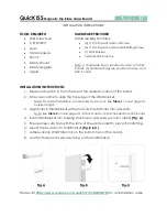
Operating Instructions
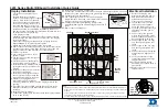
Electronic Board
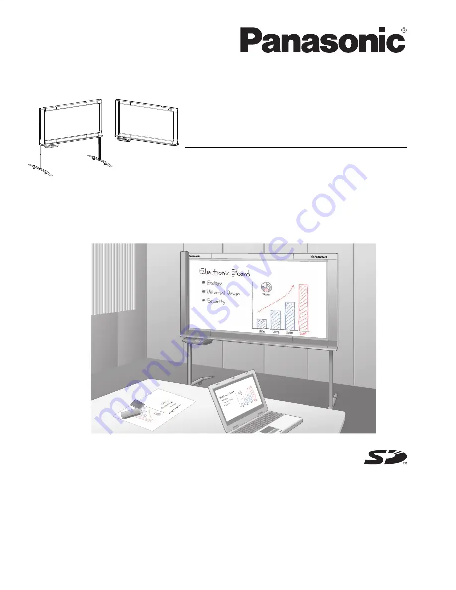
Model No.
UB-5838C
UB-5338C
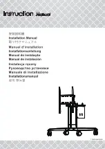
The unit in this picture is UB-5838C.
(Stand kit is optional.)
[Stand (option)]
[Wall-mounting]
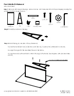
Installation Manual Included (for qualified service personnel)
•
To assemble this unit, please refer to the Installation manual on page 38 through 55.
•
Before operating this unit, please read these instructions completely and keep them carefully for future reference.
•
This unit is designed for installation by a qualified servicing dealer.
Installation performed by non-authorized individuals could cause safety-related problems with the operation of this
equipment.
For U.S.A. only:
•
To locate the closest authorized dealer in your area, please call 1-800-449-8989.
UB5838C-PJQXC0259ZA_mst.book 1 ページ 2009年5月26日 火曜日 午後2時59分