Panasonic TH-50PH20U, Operating Instructions Manual
The Panasonic TH-50PH20U user manual in Spanish (Manual De Instrucciones) is a comprehensive guide for operating this high-quality product. Explore its features, functions, and settings effortlessly with this essential manual, available for free download from manualshive.com. Get the most out of your Panasonic TH-50PH20U with this user-friendly manual.
Share
Download


Reviews:
No comments
Related manuals for TH-50PH20U
65BDL3050Q
Brand: Philips Pages: 64
BDL4256ET
Brand: Philips Pages: 40
BDL4676XL
Brand: Philips Pages: 3
BDL4970EL
Brand: Philips Pages: 52
DB32D
Brand: Samsung Pages: 190
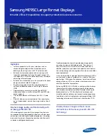
ME95C
Brand: Samsung Pages: 8
ME95C
Brand: Samsung Pages: 281
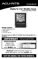
06006RM
Brand: ACU-RITE Pages: 20
VX2252mh
Brand: ViewSonic Pages: 2
PD0711
Brand: ViewSonic Pages: 24
VA2055Sa
Brand: ViewSonic Pages: 26
VX2409
Brand: ViewSonic Pages: 25

VG2433Smh
Brand: ViewSonic Pages: 25

VX2252mh
Brand: ViewSonic Pages: 25
VX4380-4K
Brand: ViewSonic Pages: 62
C4667PW
Brand: 3M Pages: 727
TH42PH20U - 42" PLASMA TV
Brand: Panasonic Pages: 5
Focus 80 Blue
Brand: Freedom Scientific Pages: 58


