background image

h

TH-42LFE7W

TH-50LFE7W

TH-65LFE7W

Operating Instructions

FULL HD LCD Display (for business use)

Model No.

English

TQB0AC0102-1

Please read these instructions before operating your set 
 and retain them for future reference.

Summary of Contents for TH-42LFE7W

Page 1: ...FE7W TH 50LFE7W TH 65LFE7W Operating Instructions FULL HD LCD Display for business use Model No English TQB0AC0102 1 Please read these instructions before operating your set and retain them for future reference ...

Page 2: ...E Setup Set up TIMER 27 PRESENT TIME Setup 27 Set up TIMER 28 Screensaver For preventing image retention 29 Setup of Screensaver Time 30 Wobbling 30 No activity power off 31 ECO Mode settings 32 Customizing the Input labels 33 Selecting the On Screen Menu Language 34 Customizing the On Screen Menu Display 34 Setup for MULTI DISPLAY 35 How to Setup MULTI DISPLAY 35 ID Remote Control Function 36 Set...

Page 3: ...iture Not placing the display on tall furniture for example cupboards or bookcases without anchoring both the furniture and the display to a suitable support Not standing the displays on cloth or other materials placed between the display and supporting furniture Educating children about the dangers of climbing on furniture to reach the display or its controls Note Image retention may occur If you...

Page 4: ...ion professional Installing the Display incorrectly may lead to an accident that results in death or serious injury Furthermore when installing on a wall a wall hanging bracket that conforms to VESA standards TH 42LFE7W VESA 200 200 TH 50LFE7W VESA 400 200 TH 65LFE7W VESA 400 400 must be used If you terminate the use of the Display on the wall ask a professional to remove the Display as soon as po...

Page 5: ...y modi cations to it place heavy objects on top of it heat it place it near any hot objects twist it bend it excessively or pull it To do so may cause re and electric shock If the power cable is damaged have it repaired at your local Panasonic dealer Do not remove covers and NEVER modify the Display yourself Do not remove the rear cover as live parts are accessible when it is removed There are no ...

Page 6: ...which neutral detergent has been diluted 100 times and then wipe it evenly with a dry cloth of the same type until the surface is dry Do not scratch or hit the surface of the panel with ngernails or other hard objects otherwise the surface may become damaged Furthermore avoid contact with volatile substances such as insect sprays solvents and thinner otherwise the quality of the surface may be adv...

Page 7: ...ge and corrosion that will damage the remote control transmitter Disposal of batteries should be in an environment friendly manner Observe the following precaution 1 Batteries shall always be replaced as a pair Always use new batteries when replacing the old set 2 Do not combine a used battery with a new one 3 Do not mix battery types example Zinc Carbon with Alkaline 4 Do not attempt to charge sh...

Page 8: ...IO OUT Connect to sound equipment see page 9 CHARGE OUT Connect to separately sold devices such as stick PCs to supply power see page 13 Connections Video equipment connection AC cord accessory Notes Insert the AC cord rmly into place When disconnecting the AC cord be absolutely sure to disconnect the AC cord plug at the socket outlet rst The included AC cord is for use with this unit only PC IN P...

Page 9: ... 4 2 18 Note Additional equipment and HDMI cable shown are not supplied with this set Pin No Signal name Pin No Signal name 1 T M D S Data2 11 T M D S Clock Shield 2 T M D S Data2 Shield 12 T M D S Clock 3 T M D S Data2 13 CEC 4 T M D S Data1 14 Reserved N C on device 5 T M D S Data1 Shield 6 T M D S Data1 15 SCL 7 T M D S Data0 16 SDA 8 T M D S Data0 Shield 17 DDC CEC Ground 9 T M D S Data0 18 5V...

Page 10: ...0 9 T M D S data 1 21 10 T M D S data 1 22 T M D S clock shield 11 T M D S data 1 shield 23 T M D S clock 12 24 T M D S clock Notes Additional equipment and cables shown are not supplied with this set Image deterioration may occur depending on the length or the quality of the cable DVI D Input Connector Pin Layouts Connection port view 9 8 1 17 24 16 Connections Stereo mini plug M3 Shared with PC ...

Page 11: ...set There is no need to use an adapter for computers with DOS V compatible Mini D sub 15P terminal The computer shown in the illustration is for example purposes only Additional equipment and cables shown are not supplied with this set Do not set the horizontal and vertical scanning frequencies for PC signals which are above or below the speci ed frequency range PC Input Terminals connection Signa...

Page 12: ... Stop bit 1 bit Flow control Signal names for SERIAL IN terminal Pin No Details 2 R X D 3 T X D 4 DTR 5 GND 6 DSR 7 8 Shorted in this set 1 9 NC These signal names are those of computer speci cations Connections Basic format for control data The transmission of control data from the computer starts with a STX signal followed by the command the parameters and lastly an ETX signal in that order If t...

Page 13: ...ppear 5V CHARGE OUT overload Please remove cable then turn the display off on In this case turn the power off and on with the remote control etc Note If there is dust in a terminal the protection circuit may function Cover the terminals such as with tape when not in use The terminals are protected by tape when shipped from the factory Power can be supplied when a separately sold stick PC or such o...

Page 14: ... power management function the power indicator turns orange in the power off state Connecting the plug to the Wall Outlet Notes Main plug types vary between countries The power plug shown at right may therefore not be the type tted to your set When disconnecting the AC cord be absolutely sure to disconnect the AC cord plug at the socket outlet rst Press the Power switch on the Display to turn the ...

Page 15: ...he power is turned ON see page 31 This message display can be set with the following menu Options menu Power On Message see page 44 When rst switching on the unit Following screen will be displayed when the unit is turned on for the rst time Select the items with the remote control Unit buttons are invalid OSD Language PRESENT TIME Setup 1 Select the language 2 Set 1 Select DAY or PRESENT TIME 2 S...

Page 16: ... has been connected to the Display Input signals will change as follows HDMI1 HDMI2 DVI PC HDMI1 HDMI input terminal in AV IN HDMI1 HDMI2 HDMI input terminal in AV IN HDMI2 PC PC input terminal in PC IN DVI DVI input terminal in DVI D IN Note Selecting is also possible by pressing the INPUT button on the unit ...

Page 17: ...gnal See page 32 Basic Controls Main Unit Remote control sensor Brightness Sensor Detects the brightness in the viewing environment See page 32 INPUT button Input signal selection see page 16 Enter Aspect button see page 19 21 Volume Adjustment Volume Up Down When the menu screen is displayed press to move the cursor up press to move the cursor down see page 21 External input terminals Connects su...

Page 18: ...ital Zoom see page 20 Remote Control Transmitter AUTO SETUP button Automatically adjusts the position size of the screen see page 22 SET UP button see page 27 42 SOUND button see page 26 Volume Adjustment Press the Volume Up or Down button to increase or decrease the sound volume level R button see page 21 Press the R button to return to previous menu screen OFF TIMER button The Display can be pre...

Page 19: ...ure Enlarged screen Description 16 9 The display of the pictures lls the screen In the case of SD signals pictures with a 4 3 aspect ratio are enlarged horizontally and displayed This mode is suited to displaying anamorphic pictures with a 16 9 aspect ratio 4 3 Pictures with a 4 3 aspect ratio are displayed with their original aspect ratio Side panels are displayed at the left and right edges of t...

Page 20: ...elected while in the following operation state When MULTI DISPLAY Setup is On see page 35 When Screensaver is running see page 29 30 While Digital Zoom is in operation Adjusting Pos Size cannot be used Select the magni cation required for the enlarged display Each time this is pressed the magni cation factor changes This is shown in the image being displayed 3 2 4 2 EXIT 2 The cursor will move 1 D...

Page 21: ... Adjust 4 Exit the menu Press Press to return to the previous menu 1 2 Signal Input label ECO Mode settings Wobbling Setup Off YUV RGB in select RGB Screensaver No activity power off Disable OSD Language English UK 2 2 Setup MULTI DISPLAY Setup Menu Display Duration 15 S Menu Transparency 20 Set up TIMER PRESENT TIME Setup Network Setup Picture menu Setup menu Pos Size menu Sound menu Menu display...

Page 22: ...ontrol is pressed Auto Setup will be executed When Auto Setup does not work Invalid is displayed Notes Auto Setup may not work when a cropped or dark image is input In such case switch to a bright image with borders and other objects are clearly shown and then try auto setup again Depending on the signal out of alignment may occur after Auto Setup Carry out ne tuning for the position size as requi...

Page 23: ... effective during only 16 9 aspect mode When Off is set H Size and V Size cannot be adjusted 1 1 Pixel Mode Adjusts the display size when 1125i or 1125p signal is input Notes On is effective during only 16 9 aspect mode Select On when you would like to replay 1920 1080 input signal Applicable input signal 1125 1080 50i 60i 24psF 24p 25p 30p 50p 60p Select Off when Àickering is shown around the ima...

Page 24: ...e If you would like to change the picture and colour of the selected Picture menu to something else adjust using the items in the Picture menu see next page Picture Adjustments 1 Advanced settings Enables ne picture adjustment at a professional level see next page While the Picture menu is displayed if either the N button on the remote control is pressed at any time or theACTION button is pressed ...

Page 25: ...lour saturation Sharpness Less More Adjusts picture sharpness Notes Carry out W B adjustment as follows 1 Adjust the white balance of the bright sections using the W B High R W B High G and W B High B settings 2 Adjust the white balance of the dark sections using the W B Low R W B Low G and W B Low B settings 3 Repeat steps 1 and 2 to adjust Steps 1 and 2 affect each other s settings so repeat eac...

Page 26: ...Select to adjust each item 3 Item Details Output Select SPEAKERS Emits sound from the built in speakers AUDIO OUT Emits sound through the AUDIO OUT terminal Sound Mode Normal Emits the original sound Dynamic Accentuates sharp sound Clear Attenuates human voice Bass Adjusts low pitch sounds Treble Adjusts high pitch sounds Balance Adjusts left and right volumes Surround Select On or Off While the S...

Page 27: ...T TIME Setup PRESENT TIME MON 99 99 Set PRESENT TIME DAY 1 2 Press to select DAY or PRESENT TIME Press to setup DAY or PRESENT TIME button Forward button Back Notes Pressing or button once changes PRESENT TIME 1 minute Pressing or button continuously changes PRESENT TIME by 15 minutes Press to select Set Press to store PRESENT TIME Setup Notes Set cannot be selected unless PRESENT TIME is set Unle...

Page 28: ... Input HDMI 1 Set the program number 2 To execute the program set to On The program is disabled when Off is set 3 Set the day The program is executed every day when Everyday is set 4 Set the power On Off 5 Set the time Pressing or button once changes Time 1 minute Pressing or button continuously changes Time by 15 minutes 6 Set the input Notes This function cannot be set unless PRESENT TIME Setup ...

Page 29: ...lect Screensaver Press to display Screensaver screen Mode selection Start setting 4 When the Mode is set to On press to select Start Press to start Screensaver The menu screen will disappear and the Screensaver will be activated To stop the Screensaver under On press the R button or any buttons on the main unit Note When the display is turned off the Scrensaver will be deactivated Press to select ...

Page 30: ...ling Off OSD Language English UK YUV RGB in select RGB No activity power off Disable After selecting Time Designation Interval or Standby after SCR Saver the relevant Time Setup will become available for selection and the Operating Time may be set Time cannot be set when Mode is On or Off Press to select Start Time Finish Time When Time Designation is selected Press to select Periodic Time Operati...

Page 31: ... any key to abort When the power is turned off due to this function a message Last turn off due to No activity power off is displayed next time the power is turned on Note During the screensaver is running this function is disabled 1 2 Signal Input label ECO Mode settings Setup Screensaver Wobbling Off OSD Language English UK YUV RGB in select RGB No activity power off Disable Press to select the ...

Page 32: ...or lights up green Notes This function operates only during input from HDMI IN terminal When the power indicator lights up orange approx 0 7 W of power is being consumed PC Power management When this function is set to On it operates under the following conditions to turn the power on or off automatically When no pictures are detected for 30 or so seconds during PC signal input ĺ Power is turned o...

Page 33: ... 3 PC DVI Input label PC DVI HDMI1 HDMI1 HDMI2 HDMI2 Customizing the Input labels This function can change the label of the Input signal to be displayed see page 16 Image input Input label PC PC DVD1 DVD2 DVD3 Blu ray1 Blu ray2 Blu ray3 CATV VCR STB Skip DVI DVI DVD1 DVD2 DVD3 Blu ray1 Blu ray2 Blu ray3 CATV VCR STB Skip HDMI1 HDMI1 DVD1 DVD2 DVD3 Blu ray1 Blu ray2 Blu ray3 CATV VCR STB Skip HDMI2...

Page 34: ...On Screen Menu Language 1 2 English UK Deutsch Français Italiano Español ENGLISH US Chinese Japanese Ɋɭɫɫɤɢɣ Russian Press to display the Setup menu Press to select Menu Display Duration Press to adjust the display duration Press to select Menu Transparency Press to adjust the transparency Press to exit from adjust mode 1 4 2 3 Customizing the On Screen Menu Display Menu Display Duration 15 S Menu...

Page 35: ...l Scale Bezel V Adjustment 10 Bezel H Adjustment 1 MULTI DISPLAY Setup 10 Press to display the Setup menu Press to select the MULTI DISPLAY Setup Press to display the MULTI DISPLAY Setup menu Press to select the MULTI DISPLAY Setup Press to select On or Off How to Setup MULTI DISPLAY 1 2 3 Item Details MULTI DISPLAY Setup Select On or Off Horizontal Scale Select 1 2 3 4 5 Vertical Scale Select 1 2...

Page 36: ...digit setting Press one of for the units digit setting 4 Notes The numbers in 2 3 and 4 should be set up quickly Adjustable ID number range is 0 99 If a number button is pressed more than two times the rst two numbers become the ID number for the remote control ID Cancellation Press button on remote control This has the same effect as pressing the buttons at the same time Notes Set the Remote ID O...

Page 37: ...No activity power off Disable OSD Language English UK YUV RGB IN select Select to match the signals from the source connected to DVI D IN terminal YUV signals YUV RGB signals RGB Press to display the Setup menu Press to select the YUV RGB in select Press to select the desired mode YUV RGB Press to exit from adjust mode 1 2 3 ...

Page 38: ...s For RGB For Digital Press ACTION button Cinema reality Off Cinema reality Press to select Cinema reality Press to set On Off Cinema reality When on the display attempts to reproduce a more natural interpretation of sources such as movie pictures which are recorded at 24 frames per second If the picture is not stable turn the setting to off Signal menu Press to select the menu to adjust Press to ...

Page 39: ... 1 280 x 768 60Hz XGA input signal irrespective of this setting Press to select XGA Mode Press to select 1024 768 1366 768 This function operates only during input from PC IN terminal Con rm that the input is set to RGB input this setting is valid only for RGB input signal Auto The H and V sync or synchronized signal is automatically selected If both input it is selected the H and V sync However t...

Page 40: ...according to the input signal Note This function can be set to the HDMI signal HDMI Range Press to select HDMI Range Press to select Video 16 235 Full 0 255 Auto H Freq V Freq kHz Hz 63 98 60 02 Signal Format 1280 1024 60 H Freq Dot Clock Freq kHz MHz 63 98 108 0 V Freq Hz 60 02 Signal Format 1280 1024 60 Displays the frequency and the type of the current input signal Display range PC input signal...

Page 41: ... software from Crestron Electronics Inc Ɣ RoomView Express Ɣ Fusion RV Ɣ RoomView Server Edition Crestron Connected is a function to connect to a system developed by Crestron Electronics Inc which manages and controls multiple system devices connected to the network For details of Crestron Connected refer to the Crestron Electronics Inc website Provided only in English http www crestron com For th...

Page 42: ...ame IP address is not used within the same network DHCP DHCP client function To obtain an IP address automatically using a DHCP server set this to On If DHCP server is not used set this to Off IP address IP address display and setting Enter an IP address if DHCP server is not used Subnet mask Subnet mask display and setting Enter a subnet mask if DHCP server is not used Gateway Gateway address dis...

Page 43: ...me Notes When Maximum VOL level is On the volume can only be adjusted between 0 and your maximum range You can hear the changed volume regardless of your volume setting before opening the options menu if you adjust the volume when Initial VOL level is On and cursor is on the menu Maximum VOL level Press button to adjust the maximum volume Off On Off Sets auto maximum volume On Sets your preferred ...

Page 44: ...able ID remote control functions Note To use the ID remote control function it is necessary to set each ID number of remote control and display unit About the setting method please refer to ID Remote Control Function see page 36 and ID select above mentioned Serial ID Sets the panel ID Control Off Disables external control by the ID On Enables the external control by the ID Studio W B Off Nullify ...

Page 45: ...ttings are as follows FUNCTION1 button Signal FUNCTION2 button Screensaver Use the FUNCTION button The menu screen is displayed Example Signal Cinema reality Signal Off Digital HDMI Range Auto H Freq V Freq kHz Hz 63 98 60 02 Signal Format 1280 1024 60 Dot Clock Freq MHz 108 0 Press the FUNCTION button to exit from the menu Press ACTION button Options 1 3 On screen display Input Search On Initial ...

Page 46: ...signal warning No Signal Error If set to On the display sends out the no signal error No Signal Error Timing Set up the detecting time for no signal error The warning of No Signal Warning and the error of No Signal Error are not sent when the no signal state is detected through any of the following functions No Signal power off Enable PC Power management DVI D Power management HDMI1 Power manageme...

Page 47: ... Network function is disabled in standby mode Network Connection Notes Make sure the broadband router or hub supports 10BASE T 100BASE TX Use a LAN cable that is compliant with CAT5 when connecting a device that supports 100BASE TX For instructions on how to connect consult your network administrator Example of network connection Display main unit rear Hub or broadband router LAN cable Shielded ȵ ...

Page 48: ... audio on mute AVMT Shutter control query Parameter 11 Picture Off picture on mute 21 Audio Off audio on mute 30 Shutter mode Off picture and audio mute deactivated 31 Shutter mode On picture and audio on mute ERST Error status query Parameter First byte 0 Second byte 0 Third byte 0 Fourth byte 0 Fifth byte 0 Sixth byte Means other error 0 or 2 Meaning of the 0 2 settings 0 Error is not detected 2...

Page 49: ...neral screen is displayed 2 From the Advanced tab click the Change Settings button next to Proxies Click Proxies and set up a proxy server 3 Deselect the Web Proxy and Automatic Proxy Con guration boxes 4 Click Apply Now Enable JavaScript 1 Display Security of Safari 2 Select Enable JavaScript under Web content 1 Start your Web browser 2 Enter the IP address set with the LAN Setup of the unit see ...

Page 50: ...are displayed Network ID information ID to identify the unit is displayed BASIC CONTROL screen OPTION CONTROL screen Click BASIC CONTROL from the menu Unit status and buttons to change settings are displayed Item Details POWER Switch OFF the unit power INPUT SELECT Switch the input signals Displayed buttons vary according to the connection status of the video device AUDIO MUTE Switch ON OFF of the...

Page 51: ...word is panasonic Up to 32 alphanumeric characters can be used for a password When the password is changed properly Password has changed message is displayed Item Details OLD PASSWORD Enter the old password NEW PASSWORD Enter the new password NEW PASSWORD RETYPE Enter the password entered in NEW PASSWORD for con rmation SAVE Save the new password The con rmation screen is displayed Click OK to cha...

Page 52: ...his operation is not available 5 Operation buttons on the menu screen Operates on the menu screen 6 Image quality adjustments Operate items related to image quality 7 Back Returns to the previous page 1 Control system Sets the information required for the communication with the controller that is connected to the Display 2 User Password Sets the password for the user rights in the operation page o...

Page 53: ...ress Displays the MAC address 3 Resolution Displays the resolution of the Display 4 Power Status Displays the status of the power 5 Source Displays the selected video input 6 Exit Return the operation page 1 Help Desk Sends or receive messages to the administrator who uses Crestron Connected Help page Click Help on the operation page The Help Desk screen is displayed ...

Page 54: ...put to the Display using a selector or distributor sound or images may not be output in the normal fashion depending on the selector or distributor used The symptoms may be improved by turning the power off and on again or by replacing the selector or distributor The RS 232C is uncontrollable Check whether the connection has been made properly see page 12 When controlling the RS 232C command on pa...

Page 55: ...5 0 25 1280x1024 85Hz 91 15 85 02 157 5 1 26 1366x768 50Hz 39 55 50 00 69 92 27 1366x768 60Hz 48 36 60 00 86 71 87 44 28 1400x1050 60Hz 65 22 60 00 122 61 29 1600x1200 60Hz 75 00 60 00 162 0 162 0 30 1920x1080 60Hz 67 50 60 00 148 5 148 5 31 1920x1200 60Hz 74 04 59 95 154 0 32 Macintosh13 640x480 35 00 66 67 30 24 33 Macintosh16 832x624 49 72 74 55 57 28 34 Macintosh21 1152x870 68 68 75 06 100 0 1...

Page 56: ...ayed 4 Press the Volume Up or Down button to select Yes 5 Press the ENTER button and wait for 10 sec 6 Press the power switch on main unit to turn the power off 2 3 Options Display Serial Number Shipping Shipping Yes No Shipping condition 5 6 Wait for 10 seconds Press the power switch on main unit to turn the power off Press to select Shipping Press to display the Shipping menu Press to select Yes...

Page 57: ...XGA UXGA compressed Horizontal scanning frequency 30 110 kHz Vertical scanning frequency 48 120 Hz Connection terminals AV IN HDMI1 HDMI2 TYPE A Connector 2 DVI D IN AUDIO DVI D 24 Pin Content Protection Stereo mini jack M3 1 Compliance with DVI Revision 1 0 Compatible with HDCP 1 1 0 5 Vrms Shared with PC IN PC IN AUDIO High Density Mini D sub 15 Pin Stereo mini jack M3 1 G with sync 1 0 Vp p 75 ...

Page 58: ...mentioning features or use of this software must display the following acknowledgement This product includes software developed by the University of California Berkeley and its contributors 4 Neither the name of the University nor the names of its contributors may be used to endorse or promote products derived from this software without specific prior written permission THIS SOFTWARE IS PROVIDED B...

Page 59: ...59 59 MEMO ...
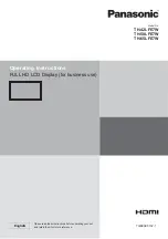
Page 60: ... can be found on its rear panel You should note this serial number in the space provided below and retain this book plus your purchase receipt as a permanent record of your purchase to aid in identi cation in the event of theft or loss and for Warranty Service purposes Model Number Serial Number Printed in China M0414 1064 ...

Reviews: