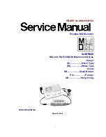
Panasonic SJ-MR200, Service Manual
The Panasonic SJ-MR200 Service Manual is a comprehensive guide that provides detailed instructions and troubleshooting tips, ensuring optimum performance for your device. Easily accessible and completely free to download, you can find this invaluable manual on our website, manualshive.com, empowering you with the knowledge needed for smooth operations.
Share
Download


Reviews:
No comments
Related manuals for SJ-MR200
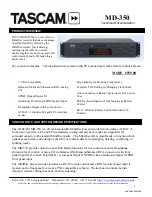
MD-350
Brand: Tascam Pages: 2
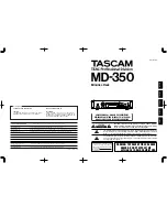
MD-350
Brand: Tascam Pages: 56
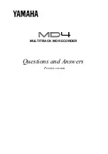
MD4
Brand: Yamaha Pages: 9
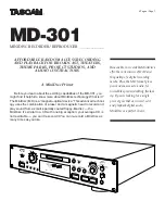
MD-301
Brand: Tascam Pages: 6

DMD-F101
Brand: Denon Pages: 36
0200JTMMDWJSCEN
Brand: JVC Pages: 38
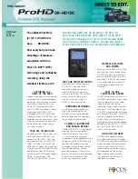
DR-HD100 - Firestore - Data Storage Wallet
Brand: JVC Pages: 2
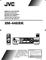
XM-448BK
Brand: JVC Pages: 45
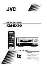
XM-EX90
Brand: JVC Pages: 60
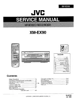
XM-EX90
Brand: JVC Pages: 88
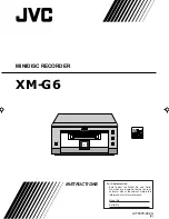
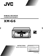
XM-G6
Brand: JVC Pages: 36
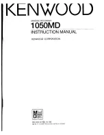
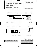
1050MD
Brand: Kenwood Pages: 54
1050MD
Brand: Kenwood Pages: 40
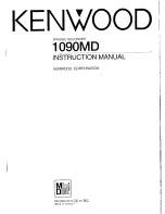
1090MD
Brand: Kenwood Pages: 56
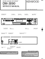
DM-3090
Brand: Kenwood Pages: 48
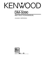
DM-5090
Brand: Kenwood Pages: 56
DM-9090
Brand: Kenwood Pages: 56
DM-B9
Brand: Kenwood Pages: 40


