


QUICK INSTRUCTION MANUAL
Safety Light Curtain Type 4
SF4D Series
ME-SF4D No.0064-86V
Thank you very much for purchasing this Panasonic product.
Please read this Instruction Manual carefully and thoroughly for the correct and opti-
mum use of this product.
Kindly keep this manual in a convenient place for quick reference.
●
This document provides brief explanations of mounting and wiring. For detailed
handling information, refer “
our web site:
https://panasonic.net/id/pidsx/global
”.
●
Instruction Manuals in the following languages are available on our Website.
Japanese, English, Chinese, Korean (excludes the
SF4D-□-01
), French, German,
Spanish (excludes the
SF4D-□-01
), Polish
1
SAFETY CAUTIONS
Always observe
●
This section explains important rules that must be observed to prevent human
injury and property damage.
■
The hazards that may occur if the product is used incorrectly are described and
classified by level of harm.
WARNING
Risk of death or serious injury.
CAUTION
Risk of minor injury or property damage.
● Use this device as per its specifications. Do not modify this device since its func
-
tions and capabilities may not be maintained and it may malfunction.
●
This device has been developed / produced for industrial use only.
●
This device is suitable for indoor use only.
●
Use of this device under the following conditions or environments is not presup-
posed. Please consult us if there is no other choice but to use this device in such
an environment.
1) Operating this device under conditions or environments not described in this manual.
2)
Using this device in the following fields: nuclear power control, railroad, aircraft,
auto mobiles, combustion facilities, medical systems, aerospace development, etc.
●
When this device is to be used for enforcing protection of a person from any dan-
ger occurring around an operating machine, the user should satisfy the regula-
tions established by national or regional security committees (Occupational Safety
and Health Administration: OSHA, the European Standardization Committee,
etc.). Contact the relative organization(s) for details.
●
In case of installing this device to a particular machine, follow the safety regula-
tions in regard to appropriate usage, mounting (installation), operation and main-
tenance. The users including the installation operator are responsible for the intro-
duction of this device.
●
Note that this device may be damaged if it is subject to a strong shock (if it is
dropped onto the floor, for example).
●
Use this device by installing suitable protection equipment as a countermeasure
for failure, damage, or malfunction of this device.
●
Before using this device, check whether the device performs properly with the
functions and capabilities as per the design specifications.
●
In case of disposal, dispose this device as an industrial waste.
WARNING
♦
Machine designer, installer, employer and operator
• The machine designer, installer, employer and operator are solely responsible
to ensure that all applicable legal requirements relating to the installation and
the use in any application are satisfied and all instructions for installation and
maintenance contained in the instruction manual are followed.
• Whether this device functions as intended to and systems including this de-
vice comply with safety regulations depends on the appropriateness of the ap-
plication, installation, maintenance and operation. The machine designer, in-
staller, employer and operator are solely responsible for these items.
♦
Engineer
• The engineer would be a person who is appropriately educated, has wide-
spread knowledge and experience, and can solve various problems which
may arise during work, such as a machine designer, installer or employer etc.
♦
Operator
• The operator should read this instruction manual thoroughly, understand its
contents, and perform operations following the procedures described in this
manual for the correct operation of this device.
• In case this device does not perform properly, the operator should report this
to the person in charge and stop the machine operation immediately. The ma-
chine must not be operated until correct performance of this device has been
confirmed.
♦
Environment
• Do not use a mobile phone or a radio phone near this device.
•
If there exists a reflective surface in the place where this device is to be in
-
stalled, make sure to install this device so that reflected light from the reflec
-
tive surface does not enter into the receiver, or take countermeasures such as
painting, masking, roughening, or changing the material of the reflective sur
-
face, etc. Failure to do so may cause the device not to detect, resulting in
death or serious injury.
•
Do not install this device in the following places:
1) Areas exposed to intense interference (extraneous) light such as high-fre-
quency fluorescent lamp (inverter type), rapid starter fluorescent lamp, stro
-
boscopic lights or direct sunlight.
2) Areas with high humidity where condensation is likely to occur
3) Areas exposed to corrosive or explosive gases
4) Areas exposed to vibration or shock of levels higher than that specified
5) Areas exposed to contact with water
6) Areas exposed to too much steam or dust
♦
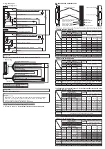
Installation
• Always keep the correctly calculated safety distance between this device and
the dangerous parts of the machine.
• Install extra protection structure around the machine so that the operator must
pass through the sensing area of this device to reach the dangerous parts of
the machine.
• Install this device such that some part of the operator’s body always remains in
the sensing area when operator is done with the dangerous parts of the machine.
•
Do not install this device at a location where it can be affected by wall reflection.
• When installing multiple sets of this device, connect the sets and, if necessary, in-
stall some barriers such that mutual interference does not occur. For details, refer
to “
6
PREVENTING MUTUAL INTERFERENCE BY DEVICE PLACEMENT
”.
•
Do not use this device in a reflective configuration.
♦
Machine in which this device is installed
• When this device is used in “PSDI mode”, an appropriate control circuit must
be configured between this device and the machine. For details, be sure to re
-
fer to the standards and regulations applicable in each region or country.
• Do not install this device with a machine whose operation cannot be stopped im-
mediately in the middle of an operation cycle by an emergency stop equipment.
• This device starts the performance after 2 seconds from the power ON. Have
the control system started to function with this timing.
♦
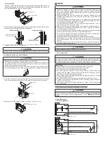
Wiring
• Be sure to carry out the wiring in the power supply OFF condition.
• All electrical wiring should conform to the regional electrical regulations and laws.
The wiring should be done by engineer(s) having the special electrical knowledge.
• Do not run the wires together with high-voltage lines or power lines or put
them in the same raceway. This can cause malfunction due to induction.
• In case of extending the cable of the emitter or the receiver, each can be ex-
tended up to 70m by using the exclusive cable (Total length 10.5m or less
when source/sink current is 350mA.). To use in a series connection, refer to
the manual on our website.
• Do not apply stress such as excessive bending or pulling to a cable or the ex-
tracted part of a cable. In particular, the material becomes hard at low tem-
perature and soft at high temperature, and thus caution is required as bending
or pulling with excessive force may cause wires to break.
• Do not control the device only at one control output (OSSD 1 / 2).
• In order that the output is not turned to ON due to earth fault of the control
output (OSSD 1 / 2) wires, be sure to ground to 0V side (PNP output) / +V
side (NPN output).
• When using this device in Korea with S-mark, be sure to ground to 0V side
(PNP output). (Applicable model:
SF4D-□
)
♦
Maintenance
• When replacement parts are required, always use only genuine supplied re-
placement parts. If substitute parts from another manufacturer are used, the
device may not come to detect, result in death or serious injury.
• The periodical inspection of this device must be performed by an engineer
having the special knowledge.
• After maintenance or adjustment, and before starting operation, test this de-
vice following the procedure specified in “
10
MAINTENANCE
.”
• Clean this device with a clean cloth. Do not use any volatile chemicals.
♦
Others
•
Never modify this device. Modification may cause the device not to detect ob
-
jects, resulting in death or serious injury.
•
Do not use this device to detect objects flying over the detection area.
• Do not use this device to detect transparent objects, translucent objects or ob-
jects smaller than the specified minimum object to be detected.
2
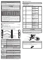
APPLICABLE STANDARDS
Type
Standards
SF4D-
□
SF4D-
□
-01
CE
○
○
NRTL (North America)
○
○
GB (Press machine in China)
○
○
Press machine in Japan
×
○
Korea with S-mark
○
×
○: Yes, ×: No
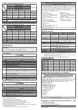
When using as a safety device for a press machine or paper shearing machine in Japan
(Applicable model: SF4D-□-01)
WARNING
In Japan, this device can only be used as a safety device for press machines and
paper shearing machines that meet the specifications below.
<Press machines>
Item
Specifications
Machine type
Press machine with an emergency stop mechanism and restart prevention mechanism
Pressure capacity
50,000kN or less
Emergency stop time
500ms or less
Stroke length
(Protection height - Die height) or less
Mold size range
Bolster width or less
<Shearing machine>
Item
Specifications
Machine type
Shearing machine with an emergency stop mechanism and restart prevention mechanism
Shearing thickness
200mm or less
Shearing width
5,000mm or less
Blade length
5,500mm or less


