© Panasonic Corporation 2009. Unauthorized copy-
ing and distribution is a violation of law.
ORDER NO. VM0902019CE
B27
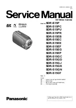
SD Video Camera
Model No.
SDR-S15P
SDR-S15PC
SDR-S15PU
SDR-S15PR
SDR-S15EB
SDR-S15EC
SDR-S15EE
SDR-S15EF
SDR-S15EG
SDR-S15EP
SDR-S15GC
SDR-S15GD
SDR-S15GJ
SDR-S15GK
SDR-S15GN
SDR-S15GT
Vol. 1
Colour
(S)...........Silver Type (except PR/EF/GD/GT)
(K)...........Black Type
(T)...........Brown Type (except PC/GD/GK)
(P)...........Pink Type (only EB)
Summary of Contents for SDR-S15EB
Page 9: ...9 4 Specifications For NTSC areas For PAL areas ...
Page 10: ...10 ...
Page 15: ...15 8 Disassembly and Assembly Instructions 8 1 Disassembly Flow Chart 8 2 PCB Location ...
Page 17: ...17 8 3 1 Removal of the Side case L unit Fig D1 Fig D2 ...
Page 22: ...22 8 3 13 Removal of the LCD unit Fig D16 8 3 14 Removal of the Monitor P C B Fig D17 ...
Page 23: ...23 8 3 15 Removal of the LCD panel Fig D18 8 3 16 Removal of the Side R P C B Fig D19 ...
Page 54: ...S7 2 LCD Section S 25 38 39 40 41 42 B29 B30 47 46 45 44 36 43 34 37 33 35 ...