Panasonic SB-W340E, Service Manual
The Panasonic SB-W340E delivers immersive audio with its powerful sound system. To maximize your experience, make sure to access the free Service Manual on manualshive.com. This comprehensive manual provides detailed instructions and troubleshooting tips to optimize your usage, enhancing your audio journey with the SB-W340E. Enjoy premium sound quality effortlessly.
Share
Download


Reviews:
No comments
Related manuals for SB-W340E
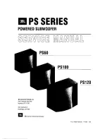
PS60
Brand: JBL Pages: 38
CS1014
Brand: JBL Pages: 4
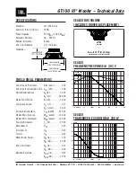
GT100
Brand: JBL Pages: 2
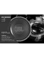
CS10
Brand: JBL Pages: 3
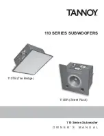
110 Series
Brand: Tannoy Pages: 16
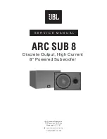
8
Brand: JBL Pages: 16
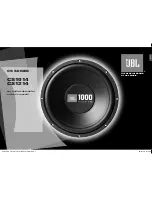
GT1000
Brand: JBL Pages: 3
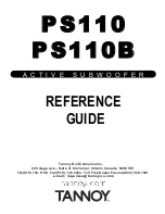
PS110
Brand: Tannoy Pages: 4
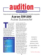
SW-200
Brand: Aaron Pages: 3
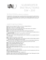
SW-200
Brand: Aaron Pages: 4
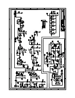
SW-200
Brand: Aaron Pages: 2

GT series
Brand: JBL Pages: 8
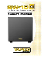
SW-10
Brand: Tapco Pages: 16

ES Series
Brand: YORKVILLE Pages: 16

BC Series
Brand: Danley Pages: 8
X8
Brand: M&K Sound Pages: 20
SUB-120
Brand: Aaron Pages: 4
SW-400
Brand: Aaron Pages: 2


