ORDER NO.
AD1404013CE
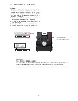
Blu-ray Disc
TM
Home Theater Sound System
Model No.
SA-BTT405P
SA-BTT405PH
SC-BTT405P
SC-BTT405PH
Colour:(K)...........Black Type
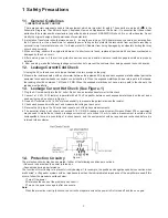
This service information is designed for experienced repair technicians only and is not designed for use by the general
public. It does not contain warnings or cautions to advise non-technical individuals of potential dangers in attempting
to service a product. Products powered by electricity should be serviced or repaired only by experienced professional
technicians. Any attempt to service or repair the product or products dealt with in this service information by anyone else
could result in serious injury or death.
WARNING
© Panasonic Corporation 2014
Unauthorized copying and distribution is a violation of law.
SB-HFS4010
SB-HC4010
SA-BTT405
Remote
Control
SB-HW4010
Notes: Please refer to the original service manual for:
• Speaker system SB-HFS4010/HC4010/HW4010, Order No:AD1403015CE