


85464849303004
REFERENCE NO
.
SM830203-04
TECHNICAL DATA & SERVICE MANUAL
Model No.
Outdoor Units
Remarks
Remarks
42
36
26
42
36
26
Type
Type
U
Single
U-26PE1U6
U-36PE1U6
U-42PE1U6
Cooling/Heating
U-26PS1U6
U-36PS1U6
U-42PS1U6
Cooling
Indoor Units
Nominal Capacity
Nominal Capacity
Indoor Units Type
Outdoor Units
4-Way Cassette
S-26PU1U6
S-36PU1U6
S-42PU1U6
with Wired Remote Controller: CZ-RTC2
with Wireless Remote Controller: CZ-RWSK1U
S-26PK1U6
Wall Mounted
Ceiling
S-26PT1U6
S-36PT1U6
S-42PT1U6
S-42PU2U6
with Wired Remote Controller: CZ-RTC2
with Wired Remote Controller: CZ-RTC2
S-36PF1U6
S-26PF1U6
Low Silhouette Ducted
U1
K1
T1
F1
F2
S-36PF2U6
S-26PF2U6
Concealed Duct
S-36PU2U6
S-26PU2U6
(CZ-36KPU3U)*
(CZ-36KPU3U)*
(CZ-36KPU3U)*
4-Way Cassette 36” × 36”
U2
K2
S-26PK2U6
Wall Mounted
T2
S-26PT2U6
Ceiling
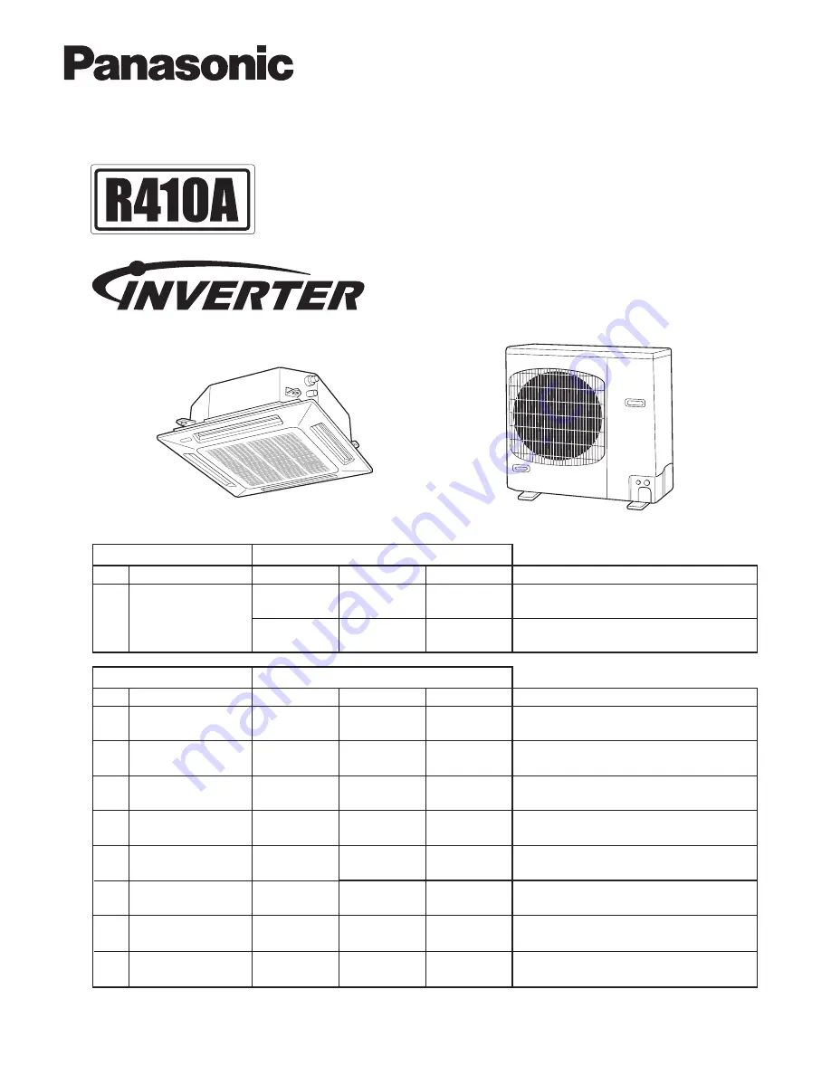
Outdoor Unit
Shows S-26PU1U6
Shows U-26PE1U6
Indoor Unit
Order No. SM830203-11CE
* Panel (optional parts)
S-42PT2U6
S-36PT2U6
SM830203-04.indb 1
15/10/13 17:17:59
Summary of Contents for : S-26PU1U6
Page 8: ...vii MEMO ...
Page 77: ...1 69 1 Specifications 1 4 Dimensional Data Outdoor Unit U 42PE1U6 U 42PS1U6 1 ...
Page 218: ...2 12 MEMO ...
Page 219: ...3 1 3 2 Indoor Units 3 2 Outdoor Units 3 14 3 ELECTRICAL DATA 3 1 3 ...
Page 220: ...3 2 3 Electrical data 3 1 Indoor Units Concealed Duct Type S 26PF2U6 S 36PF2U6 3 ...
Page 221: ...3 3 3 Electrical data 4 Way Cassette Type S 26PU1U6 S 36PU1U6 S 42PU1U6 3 ...
Page 222: ...3 4 3 Electrical data 4 Way Cassette Type S 26PU1U6 S 36PU1U6 S 42PU1U6 3 ...
Page 223: ...3 5 3 Electrical data Wall Mounted Type S 26PK1U6 3 ...
Page 224: ...3 6 3 Electrical data Wall Mounted Type S 26PK1U6 3 ...
Page 225: ...3 7 3 Electrical data Ceiling Type S 26PT1U6 S 36PT1U6 S 42PT1U6 3 ...
Page 226: ...3 8 3 Electrical data Ceiling Type S 26PT1U6 S 36PT1U6 S 42PT1U6 3 ...
Page 227: ...3 9 3 Electrical data Low Silhouette Ducted Type S 26PF1U6 S 36PF1U6 3 ...
Page 228: ...3 10 3 Electrical data Low Silhouette Ducted Type S 26PF1U6 S 36PF1U6 3 ...
Page 230: ...3 12 3 Electrical data Wall Mounted Type S 26PK2U6 3 ...
Page 232: ...3 14 3 Electrical data 3 2 Outdoor Units U 26PE1U6 3 ...
Page 233: ...3 15 3 Electrical data U 26PE1U6 3 ...
Page 234: ...3 16 3 Electrical data U 26PS1U6 3 ...
Page 235: ...3 17 3 Electrical data U 26PS1U6 3 ...
Page 236: ...3 18 3 Electrical data U 36PE1U6 3 ...
Page 237: ...3 19 3 Electrical data U 36PE1U6 3 ...
Page 238: ...3 20 3 Electrical data U 36PS1U6 3 ...
Page 239: ...3 21 3 Electrical data U 36PS1U6 3 ...
Page 240: ...3 22 3 Electrical data U 42PE1U6 3 ...
Page 241: ...3 23 3 Electrical data U 42PE1U6 3 ...
Page 242: ...3 24 3 Electrical data U 42PS1U6 3 ...
Page 243: ...3 25 3 Electrical data U 42PS1U6 3 ...
Page 244: ... MEMO 3 26 ...
Page 284: ...5 24 MEMO ...
Page 297: ...201510 ...


