background image

Model No.


PT-TW230U


PT-TW230E


PT-TW230EA


PT-TW231RU


PT-TW231RE


PT-TW231REA

© Panasonic Corporation 2012. Unauthorized 
copying and distribution is a violation of law.

LCD Projector

D10

ORDER NO. VED1203417CE
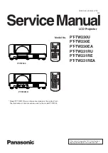
PT-TW230

PT-TW231R

*  Model PT-TW231R has an interactive module on the cabinet front. 
  The illustrations in this manual are used for the model PT-TW230.

Summary of Contents for PT-TW231RE

Page 1: ... Panasonic Corporation 2012 Unauthorized copying and distribution is a violation of law LCD Projector D10 ORDER NO VED1203417CE PT TW230 PT TW231R Model PT TW231R has an interactive module on the cabinet front The illustrations in this manual are used for the model PT TW230 ...

Page 2: ...eplacement 31 Optical Adjustments 32 Contrast adjustment 32 Condenser lens OUT adjustment 33 Relay lens OUT adjustment 34 Electrical Adjustments 35 Service adjustment menu operation 35 Circuit adjustments 36 Test points and locations 40 Service adjustment data 41 Chassis Block Diagrams 58 Chassis overview 58 System control 59 Power supply protection circuit 60 Fan control circuit 61 Troubleshootin...

Page 3: ...ead free solder Or be sure to heat the lead free solder until it melts completely before applying lead solder Aft ld i t d bl l d P C B d h k th t id f ld hi h fl t th it id 2 For US WARNING CAUTION Any unauthorized changes or modifications to this equipment will void the user s authority to operate this device There are special parts used in Panasonic LCD Projectors which are important for safety...

Page 4: ...able to use an isolation transformer in the AC power line before the service Be careful not to touch the rotation part cooling fan etc of this projector when you service with the upper case removed and the power supply turned ON Observe the original lead dress during the service If a short circuit is found replace all the parts overheated or damaged by the short circuit After the service all the p...

Page 5: ...orizontal 15 63 kHz Vertical 50 Hz 625p 576p Horizontal 31 25 kHz Vertical 50 Hz 750 720 50p Horizontal 37 5 kHz Vertical 50 Hz 1125 1080 50i Horizontal 28 13 kHz Vertical 50 Hz HD SYNC and V terminals are not compliant with 3 value composite SYNC for Video signal in cluding S Video Horizontal 15 75 kHz 15 63 kHz Vertical 50 Hz 60 Hz for HDMI signal 525p 480p 625p 576p 750 720 60p 750 720 50p 1125...

Page 6: ...rms input impedance 22 Ω and more AUDIO OUT 1 M3 stereo mini jack stereo monitor output compatible 0 V rms to 2 0 V rms valuable output impedance 2 2 kΩ and less CONTROL PORT 1 D sub 9 pin RS 232C compliant for computer control use LAN 1 for RJ 45 network connection PJLink compatible Power cable length 2 0 m 78 3 4 Cabinet Molded plastic Dimensions Width 350 mm 13 78 excluding protractions Height ...

Page 7: ...f and replace the old one with the specified type Lamp cover switch SW901 The lamp cover switch SW901 cuts off the drive signal to the lamp circuit when the lamp cover is removed or not closed completely After opening the lamp cover for replacing the lamp ass y place the lamp cover correctly otherwise the projector can not turn on Thermal fuse SW902 There is the thermal fuse SW902 inside of the pr...

Page 8: ...apter Power supply protection circuit and Fan control circuit in the Chassis Block Diagram section When the temperature inside the projector reaches a certain level the projector will be automatically shut down to protect the inside of the projector and the WARNING and ON G STANDBY R indicators start blinking When the pro jector has cooled down enough to its normal operating temperature the ON G S...

Page 9: ... Filter prevents dust from accumulating on the optical ele ments inside the projector Should the filter become clogged with dust particles it will reduce cooling fans effectiveness and may result in internal heat buildup and adversely affect the life of the projector If a Filter warning icon appears on the screen replace the filter immediately n Replacement of the air filter unit 1 Remove the air ...

Page 10: ...unit dropping Do not operate the projector with the filter removed Dust may accumulate on the optical elements degrad ing picture quality Do not put anything into the air vents Doing so may result in malfunction of the projector Do not wash the filter with water or any other liquid mat ter Otherwise the filter may be damaged n Attaching the lens cover When moving this projector or while not using ...

Page 11: ... cover is opened If pieces of glass get into your eyes or mouth Seek medical advice immediately The lamp contains mercury Consult your local municipality or your deal er about correct disposal of used lamp units Attention Do not use other than designated lamp units The part numbers of accessories and separately sold components are subject to change without notice n When to replace the lamp unit Th...

Page 12: ...nd pull it gently from the projector 4 Insert the new lamp unit in correct direction Tighten the three lamp unit fixing screws securely with a Phillips screwdriver 5 Attach the lamp cover and tighten the lamp cover fixing screw se curely with a Phillips screwdriver Attach the lamp cover by pushing it slowly opposite the direction of the arrow n Resetting the lamp runtime After replacing the lamp u...

Page 13: ...al used time in the normal mode Teco used time in the eco mode You can check the lamp runtime following to the below procedure 1 Press and hold the button on the projector or the remote control for more than 20 seconds 2 The projector used time and lamp runtime will be displayed on the screen briefly as follows Counter Projector 500H Lamp Normal 200H Eco 300H Corresponding value 425H lamp runtime ...

Page 14: ...after performing disassembly cleaning 1 Remove the cabinet top and main units following to Mechanical Disassembly 2 Remove the optical base top following to Optical Unit Disassembly If the LCD panel needs cleaning remove the LCD panel unit following to LCD panel replacement 3 Clean the optical parts with a soft cloth Clean extremely dirty areas using a cloth moistened with alcohol Caution The surf...

Page 15: ... outlet again 3 Keep pressing the ENTER button and then press the button 4 Release the button first and then release the ENTER button The PIN code lock and Logo PIN code lock will be reset as the initial PIN code at the factory and the key lock function is disabled Please refer to the owner s manual for further information of the security functions Function Description Key lock Locks operation of ...

Page 16: ...de use the projector s menu Setting Network Supply the power to the network function even after turning off the projector You can turn on off the projector via network modify network environment and receive an e mail about projector status while the projector is powered off Eco Select Eco when you do not use the projector via network The projector s network function will stop when turning off the ...

Page 17: ...s of performance and product safety Screws expression Type Diameter x Length mm T type M type Fig 1 1 Press and hold the part indicated with the arrow and press leftwards on the filter cover to release the latch and open the filter cover 2 Pull out the filter cartridge Filter cover Filter cartridge Note Do not disassemble the filter cartridge to clean up or replace the parts inside of the filter c...

Page 18: ...screw C T3x10 2 screws D M3x8 and 1 screw E T3x8 and 1 screw F T3x8 to remove the cabinet top assy 3 Loosen 1 screw G and remove the lamp cover 4 Remove 2 screws H T3x8 1 screw J M4x6 to remove the shield plate Fig 2 A A A A B B C B D D E F G H H J Lamp cover Cabinet top Shield plate AV panel A Located on the center of the cabinet bottom ...

Page 19: ... main board upward 2 Remove 1 screw D M4x6 2 screws E T3x8 3 screws F M4x6 and remove the filter shield top 3 Remove 1 screw H M3x6 and 2 screws G T3x8 and remove the filter board upward off 4 Loosen 3 screws J and pull the lamp upward off Fig 3 Main board Filter board A B C C B E E F H G G Filter shield top Lamp J Isolation sheet F D F ...

Page 20: ... the cabinet bottom 3 Remove 1 screw D T3x8 to remove the thermal fuse SW902 4 Remove 1 screw E M4x6 and 4 screws F T3x8 Disconnect the connectors CN1 on the ballast board and K6C on the power board Remove the power box top upward off 5 Remove 1 screw G M3x8 2 screws H M3x8 to remove the power board A Lamp socket A A B C C F E D F F F H G Lamp cover bottom Power board Isolation sheet Power box top...

Page 21: ... shown in the figure below Place the cables at the original position after replacing the parts Ferrite core Ferrite core Thermal fuse Lamp socket Wire band Guide Guide Guide Guide SW901 Hook Ferrite core Hook Wire band Guide Guide Wire band Wire band Fig 5 hook hook ...

Page 22: ... T3x8 SW901 Lamp cover switch T3x12 T3x30 T3x30 T3x30 T3x12 T3x12 T3x30 FN903 FN904 FN902 FN901 Main board holder Panel duct bottom 1 Remove 2 screws A T3x8 to remove the main board holder 2 Remove 2 screws B T3x12 and 5 screws C T3x8 and remove the optical unit upward off 3 Remove 9 screws D T3x8 and remove the duct assembly upward off Fig 6 D ...

Page 23: ...e 2 screws A T3x8 to remove the duct assy Remove fan FN905 and temp sensor C board 2 Remove 2 screws B T3x8 to remove the lens holder Pull the R C front board up ward off A A B B T3x30 T3x30 T3x8 T3x12 T3x12 Temp sensor C board R C front board Lens holder Speaker box Bushes FN905 Fig 7 ...

Page 24: ...ection lens removal M3x14 x2 Fig 1 x Integrator lens OUT PBS removal Fig 2 Main board holder Note The main board holder should be removed from the cabinet bottom before removing the projection lens T3x8 x2 PBS marker M3x8 x4 Lens assy Lens holder top M2 5x6 x1 Projection lens PBS Light mask PBS Integrator OUT Light mask Int Integrator IN Rugged surface is facing to PBS Rugged sur face is facing to...

Page 25: ...c Condenser lens OUT removal Fig 3 v Polarized glasses removal M2 5x6 x2 Condenser Lens OUT Polarized glass IN B Polarized glass IN G Polarized glass IN R M2 5x6 x3 Polarized glass is not re moved from the mounting base Fig 4 M2 5x6 ...

Page 26: ...assy Loosen 1 screw A and then pull the panel prism assy upward off A Note on handling the LCD panel prism assy LCD panel polarized glasses are very sensitive parts Never touch or wipe the surface When removing the dust on the surface use a commercial inert gas air spray to remove them ...

Page 27: ...ics are different between L type and R type LCD panel prism assy How to check the type of LCD panel prism assy Check the printed number on the flat cable of the G LCD panel L type LCD panel prism assy R type LCD panel prism assy Fig 5 2 Panel type check IMPORTANT NOTICE on LCD panel prism assy replacement LCD panels used for this model can not be replaced separately Do not disassemble the LCD pane...

Page 28: ... 28 Optical Parts Disassembly n Optical unit top removal Unhook 6 hooks to remove the optical unit top Optical unit top m Relay lens OUT assy removal Relay lens OUT M2 5x5 Fig 6 Fig 7 ...

Page 29: ...ounted in the specified location and direction as shown in figure below Locations and directions No Parts Name 1 Dichroic mirror B 2 Dichroic mirror G 3 Condenser lens G 4 Relay lens IN 5 Mirror R 6 Condenser lens R 7 Condenser lens B 8 Mirror B 4 Marker 2 1 5 8 7 6 5 3 Marker comes this side up Marker comes this side up ...

Page 30: ...lace it on the new main board Adjustment data setting Serial number and lamp runtime setting The projector service tool v 4 20 and serial no setting tool v1 00 can be download from the projector service web site The data of projector s model no is stored in both memory ICs IC1371 and IC1051 on the main board The model number displayed on on screen menu is stored in the memory IC IC1371 The model n...

Page 31: ...nd setting Auto calibration adjustment PC Auto calibration adjustment Component Auto calibration adjustment Video Common center adjustment 50 white adjustment PC Gamma correction adjustment White balance adjustment PC Color shading correction adjustment To setup or adjust those items the Projector Service Tool v 4 20 software is needed Refer to the owner s manual for this software for the further ...

Page 32: ... suffer of UV radiation those adjustment must be completed within 25 minutes Before adjustment Input a 100 of black raster signal 1 Loosen 1 screw A Fig 1 on the polarized glass mounting base which you intend to adjust 2 Adjust the slot B to obtain the darkest brightness on the screen by using a slot screwdriver 3 Tighten the screw A to fix the polarized glass mount ing base Repeat steps 1 to 3 fo...

Page 33: ... Fig 2 1 loosen 1 screw C and adjust the slot D to make color uniformity in white by using a slot screwdriver 2 If the shading appears on the top or bottom of the screen as shown in Fig 2 2 loosen 2 screws E and adjust the slots F to make color uniformity in white by using a slot screwdriver 4 Tighten screws C and E to fix the condenser lens OUT assy Note The relay lens adjustment must be carried ...

Page 34: ...justment base of relay lens OUT assy to make color unifor mity in white If the shading appears on the left or right of the screen as shown in Fig 3 loosen 1 screw G by using a hex screwdriver and adjust the slot H to make color uniformity in white by using a slot screwdriver 4 Tighten the screw G to fix the relay lens OUT assy White G H Fig 3 Moving of slot H ...

Page 35: ...essing the MENU button increase or ENTER button decrease and se lect the adjustment item no by pressing the pointer e or d button and change the data value by pressing the 7 or 8 button Refer to the Service adjustment data table for further description of adjustment group no item no and data value To exit the service mode To exit the service mode press the button Service adjustment menu operation ...

Page 36: ...ROTECTION DURING SERVICING CAUTION To prevent suffer of UV radiation those adjustments must be completed within 25 minutes Adjustment Condition Input signal Computer signal 0 7Vp p 75Ω terminated XGA Video signal 1 0Vp p 75Ω terminated Composite video signal Component video signal 1 0Vp p 75Ω terminated Component video signal 480i Image mode Standard Lamp power Normal Note Please refer to Service ...

Page 37: ... the service mode 2 Adjust the amplitude a of waveform at each test point to be minimum by changing the data value of Group No Group No Test Points 0 3 TP35G 0 4 TP35R 0 5 TP35B a White Level Pedestal adjustment PC Equipment Oscilloscope 1 Enter the service mode 2 Adjust the black level on each test point to be minimum by changing the data value of Group No Group No Test Points 0 0 TP35G 0 1 TP35R...

Page 38: ...mode Video Input signal Composite video signal Signal pattern 16 step gray scale 1 Enter the service mode 2 Select Group 260 No 0 and then change data value from 0 to 1 After the auto calibration com pleted OK will appear on the screen Below adjustment is performed when the above auto calibration is failed Pedestal adjustment Component Input signal 480i component signal Signal pattern 16 step gray...

Page 39: ...0 white computer signal 4 Select Group 100 No 6 and change the data val ue to make the reading of illuminance meter to be A x 22 8 White balance adjustment PC Input mode Computer 1 RGB Input signal XGA computer signal Signal patterns 16 step gray signals 1 Enter the service mode 2 Select Group 100 No 7 Red or 8 Blue and change Data values respectively to make a proper white balance Group No Adjust...

Page 40: ... 40 Electrical Adjustments MAIN BOARD Test points and locations IC561 K5B K5G K5R K6E K6G K6J K6P K6F IC1371 K8F K8H K8K K8L K8R K8S IC501 I C 5 3 1 TP35B TP35R TP35G K8D K6W ...

Page 41: ...een Hsysterisis Enable 0 0 1 12 HS1TH 4 0 7 13 HS0TH 4 0 7 100 PreCoast PC Signal 3 0 63 101 PostCoast PC Signal 8 0 63 120 PreCoast PC Video 480i 7 0 63 121 PostCoast PC Video 480i 13 0 63 122 PreCoast PC Video 575i 7 0 63 123 PostCoast PC Video 575i 13 0 63 124 PreCoast PC Video 480p 7 0 63 125 PostCoast PC Video 480p 13 0 63 126 PreCoast PC Video 575p 7 0 63 127 PostCoast PC Video 575p 13 0 63 ...

Page 42: ...on 0x1000 0 9999 Group 20 Video Decoder 0 Y Level Composite S Video Y Level ADC RGB Gain 10 10 0 255 Composite S Video 1 C Level Composite S Video C Level ADC Saturation 115 115 0 255 Composite S Video 3 XCXL Level Cross Chroma Cross Luma Level 3 0 5 4 C2DNBANDWIDTH Comb 2D Narrow Bandwidth 3 3 0 3 NTSC PAL 5 C2DWBANDWIDTH Comb 2D WidBandwidth 4 4 0 7 NTSC PAL 6 C2DCNMINLEAK Comb 2D ChromNarrow Ba...

Page 43: ...Y2 NSREGIONUV2 40 0 1023 4 Noise Gain Level NSFILTERY NSFILTERUV 0 0 255 Group 47 Noise Reduction Time Effective only for N R L1 0 Noise Pixel Range NSRANGEY NSRANGEUV 1 0 2 1 Noise Region 0 NSREGIONY0 NSREGIONUV0 12 0 1023 2 Noise Region 1 NSREGIONY1 NSREGIONUV1 24 0 1023 3 Noise Region 2 NSREGIONY2 NSREGIONUV2 40 0 1023 4 Noise Gain Level NSFILTERY NSFILTERUV 50 0 255 Group 49 Noise Reduction Ti...

Page 44: ... 512 0 1023 3 Center Tint 90 90 90 90 90 90 0 180 4 Center Sharpness 16 16 16 16 16 16 16 5 Alpha Contrast 40 40 40 40 40 40 0 1000 6 Alpha Brightness 140 140 140 140 140 140 0 1000 7 Alpha Color 70 70 70 70 70 70 0 1000 8 Alpha Tint 10 10 10 10 10 10 0 1000 9 Alpha Sharpness 10 10 10 10 10 10 0 1000 Group 100 Panel Service 0 G SubGain 2048 2068 2024 2024 1950 1950 1 830 1900 2048 2068 2024 2024 1...

Page 45: ...8 GhostG Pos 6 0 31 49 GhostB Pos 6 0 31 50 GhostR Cent 0 0 2047 51 GhostR Start 128 0 255 52 GhostR End 128 0 255 53 GhostG Cent 0 0 2047 54 GhostG Start 128 0 255 55 GhostG End 128 0 255 56 GhostB Cent 0 0 2047 57 GhostB Start 128 0 255 58 GhostB End 128 0 255 59 BlockR1 0 0 2047 MIN MAX Cyclic Operation 60 BlockG1 0 0 2047 MIN MAX Cyclic Operation 61 BlockB1 0 0 2047 MIN MAX Cyclic Operation 62...

Page 46: ...G DCOffset N7 0 0 2047 124 G DCOffset N8 0 0 2047 125 G DCOffset N9 0 0 2047 126 G DCOffset N10 0 0 2047 127 G DCOffset N11 0 0 2047 128 G DCOffset N12 0 0 2047 129 B DCOffset NGain 0 0 1023 130 B DCOffset N1 0 0 2047 131 B DCOffset N2 0 0 2047 132 B DCOffset N3 0 0 2047 133 B DCOffset N4 0 0 2047 134 B DCOffset N5 0 0 2047 135 B DCOffset N6 0 0 2047 136 B DCOffset N7 0 0 2047 137 B DCOffset N8 0 ...

Page 47: ...018 0 1023 193 R_V_INPUT_ SETP_4096 1016 0 1023 194 G_V_INPUT_SETP_0 20 0 1023 195 G_V_INPUT_SETP_512 17 0 1023 196 G_V_INPUT_SETP_1024 13 0 1023 197 G_V_INPUT_SETP_1536 9 0 1023 198 G_V_INPUT_SETP_2048 4 0 1023 199 G_V_INPUT_SETP_2560 0 0 1023 200 G_V_INPUT_SETP_3072 1020 0 1023 201 G_V_INPUT_SETP_3584 1018 0 1023 202 G_V_INPUT_SETP_4096 1016 0 1023 203 B_V_INPUT_SETP_0 20 0 1023 204 B_V_INPUT_SE...

Page 48: ... B ENBX11N 8 0 31 12 R FPDDR1M 0 0 0 3 13 1 0 0 1 14 1 0 0 1 15 R PARA1 0 0 7 16 1 0 1 17 R PARA2 868 0 1023 18 R PARA3 867 0 1023 19 R FPDDR1 868 0 1023 20 R FPDDR11 921 0 1023 21 G FPDDR1M 2 2 0 3 22 1 0 0 1 23 1 0 0 1 24 G PARA1 0 0 7 25 1 0 1 26 G PARA2 868 0 1023 27 G PARA3 867 0 1023 28 G FPDDR1 868 0 1023 29 G GPDDR11 921 0 1023 30 B FPDDR1M 2 2 0 3 31 1 0 0 1 32 1 0 0 1 33 B PARA1 0 0 7 34...

Page 49: ...freq Panel frequency of input signal 1 0 1 2 Field Sense Invert Enable Reverse Processing of FLDINVSetting Value 0 Disable Used FLDINV Setting Value 1 Enable Used Reversed FLDINV Setting Value 0 0 1 4 Sub Image Enable 0 Disable Service Adjustment Dsiable Used all the Center Values 1 Enable Service Adjustment Enable 1 0 1 6 Zoom Accelerator Enable 0 Zoom Accelerator OFF 1 Zoom Accelerator ON No las...

Page 50: ...ge Point for Mimmer 4 1 16 16 DIMMER_AVERAGE_ DATA Luminance Data Avarage Value for Dimmer Read only 17 DIMMER_LEVEL_AUTO Current Dimmer Leverl Read only 18 DIMMER_LEVEL_ NORMAL Normal Dimmer Level 15 0 15 19 DIMMER_LEVEL_ECO Eco Dimmer Level 0 0 15 20 Panel life mode Panel life mode 0 0 1 21 VOLTAGE_LEVEL Lamp Voltage Unit 8bit Raw Data Read only 22 DIMMER_LEVEL_HIGH 15 0 15 Group 230 VBI Slice L...

Page 51: ...on the lamp Right to change the Lamp mode 3 0 5 21 Temp B Warning Offset Time 3 0 5 22 Temp C Warning Offset Time 3 0 5 23 Temp B A Warning Offset Time 3 0 5 24 Temp C A Warning Offset Time 3 0 5 Group 254 Fan Control Range Setting Temp Voltage Normal OFF Ceiling OFF Hiland Normal ON1 DIF ON2 Hiland Ceiling ON1 DIF ON2 10 High Fan Control Min Temp 35 35 0 32 0 32 20 100 11 High Fan Control Max Tem...

Page 52: ...osition 500 0 1000 2 GAIN AREA H START White Level Acquiring Area H Start Position 25 0 1000 3 GAIN AREA V START White Level Acquiring Area V Start Position 500 0 1000 4 Image AREA H WIDTH Black White Level Acquiring Area 13 0 4095 5 Image AREA V HIGHT Black White Level Acquiring Area Height 9 0 4095 6 OFFSET target Target Value of Black Level Adj 3 0 127 7 OFFSET torelance Torelance of Black Leve...

Page 53: ...shold 5 0 10 0 10 Not matched 3 Fine Phase Do Phase Adj after Total Dot Adj 1 0 1 0 Executes Fine Phase 1 Not Execute 4 BLKDET Black Level Detection Area 1 0 7 5 PHASEMSK Phase Detection Filter 0 0 3 0 Effective All Bit 1 Disable Lower 1 bit 2 Disable Lower 2 bit 3 Disable Lower 3 bit Group 290 Panel Type 0 GammaL R View 0 0 20 0 Gamma for L Turn 20 Gamma for R Turn Read only 1 GammaL R Change Set...

Page 54: ... 0 4095 3 V Back Porch 18 0 4095 4 Disp Line 458 0 4095 Group 501 Composite PAL For Composite S Video 1 Disp Dots 658 0 4095 2 H Back Porch 34 0 4095 3 V Back Porch 22 0 4095 4 Disp Line 536 0 4095 Group 502 Composite SECAM For Composite S Video 1 Disp Dots 652 0 4095 2 H Back Porch 28 0 4095 3 V Back Porch 22 0 4095 4 Disp Line 536 0 4095 Group 510 SCART 480i 1 Disp Dots 674 0 4095 2 H Back Porch...

Page 55: ...ts 1872 0 4095 2 H Back Porch 256 0 4095 3 V Back Porch 54 0 4095 4 Disp Line 1052 0 4095 Group 527 YCbCr 1080i 50 0 Total Dots 2640 0 4095 Read only 1 Disp Dots 1870 0 4095 2 H Back Porch 257 0 4095 3 V Back Porch 54 0 4095 4 Disp Line 1052 0 4095 Group 528 YCbCr 1035i 0 Total Dots 2200 0 4095 Read only 1 Disp Dots 1872 0 4095 2 H Back Porch 256 0 4095 3 V Back Porch 92 0 4095 4 Disp Line 1012 0 ...

Page 56: ...6 0 4095 2 H Back Porch 310 0 4095 3 V Back Porch 34 0 4095 4 Disp Line 702 0 4095 5 Clamp 1 0 255 Read only 6 Clamp Width 31 0 255 Read only Group 546 RGB Video 1080i 60 0 Total Dots 2200 0 4095 1 Disp Dots 1872 0 4095 2 H Back Porch 260 0 4095 3 V Back Porch 58 0 4095 4 Disp Line 1046 0 4095 5 Clamp 1 0 255 Read only 6 Clamp Width 31 0 255 Read only Group 547 RGB Video 1080i 50 0 Total Dots 2640...

Page 57: ...teps 0 0 255 8 VSBEG 2 0 15 Group 565 HDCP 1080i 50 7 OverScan Over Scan Rate 0 25 5 at 0 1 steps 0 0 255 8 VSBEG 2 0 15 Group 566 HDCP 1035i 7 OverScan Over Scan Rate 0 25 5 at 0 1 steps 0 0 255 8 VSBEG 2 0 15 Group 981 Color Shading Adj Offset L R 0 R Max 0 0 0 255 1 R Mid1 0 0 0 255 2 R Mid2 0 0 0 255 3 R Min 0 0 0 255 4 G Max 0 0 0 255 5 G Mid1 0 0 0 255 6 G Mid2 0 0 0 255 7 G Min 0 0 0 255 8 ...

Page 58: ...20 2 12 1 82 260 258 265 264 262 3 7 13 SP901 SPEAKER PC_L R 18 4 HDMI_L R VIDEO S VIDEO VIDEO_L R OUT_L R RGB H V RGB H V TP35B B G R HS1 VS1 HS2 VS2 IC531 G D A S H L3E06200 IC561 R D A S H L3E06200 IC3801 RS232C DRIVER MAX232 IC8801 NETWORK AX11005 IC9882 INVERTER TP35G TP35R Q1001 R1 G1 B1 S_CHROMA S_Y VIDEO Q1002 Q1005 263 SOG1 Q1007 Q2011 172 78 256 5 1 9 13 R2 G2 B2 Q1003 86 SOG2 Q1008 409 ...

Page 59: ... ON_50V 419 P_FAIL LAMP_DC_ON 215 FAN_SW1 FAN_SW1 190 89 275 191 189 IC3804 MUTE KEY1 KEY1 KEY2 267 28 KEY2 126 164 R C_PW R C R C_PW SCL1 SDA1 SCL2 SDA2 214 211 294 SCL0 SDA0 293 212 290 208 30 120 FAN_CON_C 374 IC301 SCALER Q6846 D6831 D6833 D6835 Q5035 LAMP REPLACE WARNING POWER IC4891 NAND IC9882 INVERTER 2 6 8 13 22 12 7 9 10 1 3 10 19 3 6 3 6 5 15 20 23 11 K8R K6R K8S 2 1 K8H 4 5 1 K8D K29D ...

Page 60: ..._150V LAMPDC_ON POWER_SW IC4891 NAND S6V S16V S 5V 8 9 5 6 3 11 IC8821 TEMP SENSOR B MCP9801 PANEL ROOM LAMP IC8811 TEMP SENSOR A MCP9801 IC8831 TEMP SENSOR C MCP9801 LAMP_DET 285 2 13 P_FAIL P Fail L 215 188 95 ON_50V 419 ON_16V 96 Power On H ON_18V ON_18V 347 Power On H LAMP_DC_ON 89 293 212 SCL0 SDA0 IC9882 INVERTER IC9885 SUB CPU SW901 S16V FAN_A IC7811 D3613 D8092 D8093 D8094 D591 D592 2 Q583...

Page 61: ...IC7841 Q7864 Q7842 P_FAIL FAN_SW1 D3613 FANC D3644 D3614 D3626 K6Q FN907 1 2 D3631 IC8811 TEMP SENSOR A MCP9801 2 1 IC8821 TEMP SENSOR B MCP9801 MAIN BOARD IC301 SCALER Power On H IC4891 NAND 1 2 4 190 293 212 SCL0 SDA0 Power Error On P_Fail H SIGNAL MODE POWER ON STAND BY H L NORMAL ERROR H L FAN_SW1 P_FAIL P_FAIL FAN_ERR TPFANC TPFANB K8S K8H 11 K8L 2 1 1 LAMP_SCI 30 FAN_CON_A 374 FAN_CON_C 120 ...

Page 62: ... If the projector is turned off again the projector may have the internal error It needs to check up or servic ing Provide good installing condition to your projector Move the installation of the projector away from the duct or vent Replace filter unit WARNING indicator Indicator status Status No illumination or flashing The power cord is unplugged RED Lit The power cord is plugged The projector i...

Page 63: ...upply secondary circuits Check fan operation and power supply lines and the driving signal status The P_FAIL signal Error L is sent to pin 215 of IC301 SCALER when the abnormality occurred inside the projector and then the IC301 sends the shutdown signal LAMP_DC_ON to the power supply circuit to stop its operation and the signal LAMP_SCI output from IC9885 SUB CPU is sent to the lamp ballast board...

Page 64: ...ng stage Check IC301 Scaler and peripheral circuit Check S5V and S 5V supply voltages No picture with all of computer input sources Yes Yes No No No No Check AV source selecting and decoding stage S Video source Check S video signal Y C S_CHROMA signal is applied to pin 265 of IC301 Scaler and S Y signal is applied on pin 264 of IC301 Composite video source Check composite video signal Video The c...

Page 65: ...C001 The Mute signal is output from pin 267 of IC 301 Scaler The OUT_DET signal is sent from Audio Out terminal Mute On H at pin 267 of IC301 L at pin 1 of IC001 Check if the audio sig nal is observed at pins 20 and 23 of IC001 Yes No Check IC5001 and peripheral circuit Check the 12V power supply Check if the audio sig nal is observed at pins 7 and 15 of IC5001 No Troubleshooting ...

Page 66: ...K_PW 3 Wired Serial Control Clock O 368 E20 RXD_PW Serial Control RXD I 30 E26 FAN CON_A FAN CON_A O 96 F1 ON_16V Standby Power Control 16V S 5V O 189 F2 PW_MASTER_SDI Sub CPU Communication I 420 F5 POWER_SW_LAN Network Power SW O 298 F23 Option SW Option Switch I 128 F25 FAN CON_B FAN CON_B O 95 G1 ON_150V Standby Power Control 15V O 188 G2 ON_33V Standby Power Control 3 3V O 273 G3 IRM_RST Color...

Page 67: ... 67 FA5550NG P F control IC621 IC Block Diagrams L3E06200 D A S H LCD Driver IC501 IC531 IC561 ...

Page 68: ... 68 IC Block Diagrams L3E07111 Digital Gamma and Driver IC401 MB95F353EPFT Sub CPU IC9885 ...

Page 69: ...ator Burst mode OCP threshold comparator Restart timer Latch circuit reset comparator UVLO comparator VUL VCC start VCC stot VCC startup off VCC startup on VTH OCL VTH burst limit Q1 VOVP Vref IF B OVP comparator Thermal Shutdown circuit Zero current detection circuit Turn on dead timer Standby circuit ON width timer S Q R 1 2 3 4 7 9 5 Z C F B NJW1156 Audio Selector IC5001 ...

Page 70: ...d Spectrum PLL Color Matrix Gamma CLTs Color Space Expander Display Port PW190 Internal Block Diagram Video Enhancement Color Space Converter Image Blending OSD Control and Generation Deinterlacer Scaler Memory Controller Internal Memory VBI Memory Interface VBI Memory Interface Input Port 0 Sync Decoder Auto Image Optimizer Input Port 1 Sync Decoder Auto Image Optimizer 2DVideo Decoder GPIO PWM 2...

Page 71: ...l symbol have special characteristics impotant for safety When replacing any of these components use only the manufacturer s specified parts Before ordering the service parts comfirm the parts number with the Ref No in the parts list and the exploded view Exploded Views Parts List Models PT TW230U PT TW230E PT TW230EA PT TW231RU PT TW231RE PT TW231REA ...

Page 72: ...t top assembly Cabinet bottom 1 assembly A100 MAIN BOARD A602 FILTER BOARD C12 S02 C08 M08 C01 1 C01 C10 S02 C09 C07 C03 C02 S03 A901 BALLAST BOARD A601 POWER BOARD FN907 FN906 M04 M17 M15 M13 M13 M13 LP900 M16 C06 A2000 KEY SW BOARD Only models PT TW231R series have this parts C14 ...

Page 73: ...W231RE TW231REA Filter duct assembly Cabinet bottom 2 assembly FN901 A605 TEMP SENSOR C BOARD A604 TEMP SENSOR A BOARD M10 M09 A603 R C BOARD C04 C04 1 SW901 FN902 FN903 FN904 S01 S01 S01 S01 M14 M01 M02 SW902 FN905 M11 M12 M18 M19 M03 C11 C05 C05 C04 2 SP901 ...

Page 74: ...SPL 4 PT TW230U TW230E TW230EA PT TW231RU TW231RE TW231REA Exploded Views Projection Lens PBS and Integrator lens assembly L13 L09 L08 L07 M05 M06 S05 S05 S07 ...

Page 75: ...SPL 5 Exploded Views PT TW230U TW230E TW230EA PT TW231RU TW231RE TW231REA Condenser lens OUT assembly Polarized Glass IN assembly S04 S04 S04 L04 S04 L02 R Red L02 G Green L02 B Blue S04 S04 ...

Page 76: ...SPL 6 PT TW230U TW230E TW230EA PT TW231RU TW231RE TW231REA Exploded Views LCD Panel Prism Assembly Relay lens OUT assembly L01 S06 M07 L06 S04 ...

Page 77: ...230E TW230EA PT TW231RU TW231RE TW231REA L10 L15 L14 L12 L11 L03 L05 In the optical unit CAUTION Part must be placed in specified direction when replacing the optical parts Please see Optical parts disassembly for further instructions ...

Page 78: ...SPL 8 PT TW230U TW230E TW230EA PT TW231RU TW231RE TW231REA Exploded Views Labels W02 W04 W05 W03 W01 W06 Packing P01 P02 ...

Page 79: ... HOLDER AC CORD STOPPER STRAP VGA CABLE INTERACTIVE LIGHT PEN 1 INTERACTIVE PONTER 1 INTERACTIVE USB CABLE 1 Not service parts Product Model No ET PEN100 Not service parts Product Model No ET PNT100 CABLE HOLDER 1 FERRITE CORE 1 Accessories see accessories parts list 1 These parts are exclusive for model PT TW231R series ...

Page 80: ... TW230EJ 6550052131 SETUP INST LW4SC TW230EA TW230EAJ 6451053893 ASSY REMOCON MXEJ 6520032767 CORE CLAMP TW231R 6451043719 CABLE USB CL 2 TW231R 6103547107 FIXER BTM KJ8AE TW231R MECHANICAL PARTS CABINET PARTS C01 6103595665 CABINET TOP SERVIEC KW4AC C01 1 6103592374 DEC CONTROL SHEET KW4CC C02 6103592282 ASSY COVER LMP KW4CC C03 6103490083 DEC INLAY LED KJ8YC C04 6103595689 CABINET BTM SERVICE KW...

Page 81: ... POLG IN KJ8YC L02 B 6103465548 ASSY POL B IN KD5AC L03 6450964657 LENS CONDENSER G L04 6450990564 LENS CONDENSER OUT L05 6450990571 LENS RELAY IN L06 6450990601 LENS RELAY OUT L07 6450999161 LENS INTEGRATOR IN L08 6450999178 LENS INTEGRATOR OUT L09 6451023902 LENS PROJECTION L10 6451029980 LENS RELAY IN L11 6451010247 MIRROR B L12 6451010254 MIRROR R L13 6451053428 PRISM PBS L14 6451046918 DICHRO...

Page 82: ...ILM Metalized Polyphenylene Sulfide Film MT PEN FILM Metalized Polyethylenenaphthalate Film CAPACITOR Other CARBON 4 7K J A 1 4W Rated Wattage Performance Symbols A General B Non flammable Z Low noise Other Temperature coefficient Tolerance Symbols A 0 05 B 0 1 C 0 25 D 0 5 F 1 G 2 J 5 K 10 M 20 P 5 15 Z 0 ohm Rated value ohms K 1 000 M 1 000 000 Material CARBON Carbon MT FILM Metal Film OXIDE MT ...

Page 83: ... 0 068U K 16V C1017 3034420519 CERAMIC 0 068U K 16V C1018 3034420519 CERAMIC 0 068U K 16V C1019 3034093426 CERAMIC 0 1U K 16V C1049 3034093426 CERAMIC 0 1U K 16V C1061 3033983312 ELECT 47U M 10V C1092 3033583215 CERAMIC 10U K 6 3V C1103 3034093426 CERAMIC 0 1U K 16V C1105 3034093426 CERAMIC 0 1U K 16V C1331 3032761911 CERAMIC 22P J 50V C1332 3033092519 CERAMIC 27P J 50V C1371 3034093426 CERAMIC 0 ...

Page 84: ...426 CERAMIC 0 1U K 16V C3581 3032763113 CERAMIC 33P J 50V C3582 3032763113 CERAMIC 33P J 50V C3583 3032763113 CERAMIC 33P J 50V C3584 3032763113 CERAMIC 33P J 50V C3586 3032763113 CERAMIC 33P J 50V C3587 3032763113 CERAMIC 33P J 50V C3588 3032763113 CERAMIC 33P J 50V C3598 3033945815 CERAMIC 4 7U K 16V C3599 3034331112 CERAMIC 1U K 10V C361 3034331112 CERAMIC 1U K 10V C362 3034331112 CERAMIC 1U K ...

Page 85: ...AMIC 10U K 6 3V C568 3034014312 ELECT 47U M 25V C569 3033727510 CERAMIC 2 2U K 6 3V C5705 3033763112 ELECT 100U M 25V C5706 3034093426 CERAMIC 0 1U K 16V C5707 3033246417 CERAMIC 0 022U K 16V C5708 3033975713 ELECT 100U M 10V C571 3033978219 CERAMIC 2 2U K 25V C572 4034670911 CERAMIC 0 1U K 25V C573 4034670911 CERAMIC 0 1U K 25V C574 4034670911 CERAMIC 0 1U K 25V C576 4034670911 CERAMIC 0 1U K 25V...

Page 86: ...12P J 50V C8860 3032152214 CERAMIC 0 01U K 50V C8863 3033915412 ELECT 22U M 6 3V C9875 3033058812 CERAMIC 47P J 50V C9878 3033246417 CERAMIC 0 022U K 16V C9882 3034093426 CERAMIC 0 1U K 16V C9883 3033921215 ELECT 47U M 6 3V C9884 3034093426 CERAMIC 0 1U K 16V D001 3072350816 DIODE 1SS387 TPL3 D002 3072350816 DIODE 1SS387 TPL3 D1001 3072091214 ZD UDZS TE 176 2B D1002 3072091214 ZD UDZS TE 176 2B D1...

Page 87: ...L3501 6520028500 INDUCTOR 330OHM P L3531 6520028500 INDUCTOR 330OHM P L3534 9450412210 INDUCTOR 0 12U K L3561 6520028500 INDUCTOR 330OHM P L3622 6520028524 INDUCTOR 220OHM P L3623 6520028524 INDUCTOR 220OHM P L3626 6520028524 INDUCTOR 220OHM P L3627 6520028524 INDUCTOR 220OHM P L3628 6520028685 INDUCTOR 1000OHM P L3630 6520028524 INDUCTOR 220OHM P L3631 6520028685 INDUCTOR 1000OHM P L3633 65200286...

Page 88: ... GLAZE 1 5K JA 1 16W R1070 3012637420 MT GLAZE 75 JA 1 16W R1072 3012637420 MT GLAZE 75 JA 1 16W R1075 3012637420 MT GLAZE 75 JA 1 16W R1077 3012637420 MT GLAZE 75 JA 1 16W R1078 3012637420 MT GLAZE 75 JA 1 16W R1079 3012637420 MT GLAZE 75 JA 1 16W R1080 3012637420 MT GLAZE 75 JA 1 16W R1081 3012251418 MT GLAZE 47K JA 1 16W R1083 3012258110 MT GLAZE 10 JA 1 16W R1084 3012249316 MT GLAZE 1K JA 1 16...

Page 89: ...12251814 MT GLAZE 47 JA 1 16W R416 3012251814 MT GLAZE 47 JA 1 16W R418 3012251814 MT GLAZE 47 JA 1 16W R419 3012251814 MT GLAZE 47 JA 1 16W R422 3012251814 MT GLAZE 47 JA 1 16W R423 3012251814 MT GLAZE 47 JA 1 16W R424 3012251210 MT GLAZE 4 7K JA 1 16W R472 3012261516 MT GLAZE 0 000 ZA 1 16W R4834 3012253818 MT GLAZE 1 5K JA 1 16W R4862 3012257915 MT GLAZE 220 JA 1 16W R4863 3012257915 MT GLAZE 2...

Page 90: ...GLAZE 30K JA 1 16W R7848 3012249019 MT GLAZE 10K JA 1 16W R7863 3012249316 MT GLAZE 1K JA 1 16W R7871 3013018010 MT GLAZE 1 5K FA 1 16W R7872 3012942910 MT GLAZE 560 FA 1 16W R7873 3012646115 MT GLAZE 20K FA 1 10W R7874 3012994810 MT GLAZE 2 7K FA 1 16W R7878 3012249019 MT GLAZE 10K JA 1 16W R7879 3012249316 MT GLAZE 1K JA 1 16W R7881 3012249316 MT GLAZE 1K JA 1 16W R7882 3012250213 MT GLAZE 3 3K ...

Page 91: ...RK 47X4 1 16W RB431 9450370831 R NETWORK 47X4 1 16W RB432 9450370831 R NETWORK 47X4 1 16W RB433 9450370831 R NETWORK 47X4 1 16W RB434 9450370831 R NETWORK 47X4 1 16W RB436 9450370831 R NETWORK 47X4 1 16W RB437 9450370831 R NETWORK 47X4 1 16W RB501 9450370817 R NETWORK 0X4 1 16W RB503 9450370817 R NETWORK 0X4 1 16W RB504 9450370817 R NETWORK 0X4 1 16W RB506 9450370817 R NETWORK 0X4 1 16W RB531 9450...

Page 92: ...26520 CORE PIPE Q622 3051739816 TR 2SC3928A1R Q641 3051739816 TR 2SC3928A1R Q642 3051739816 TR 2SC3928A1R Q651 4052203016 TR ISA1235AC1F R610 3012533712 MT GLAZE 0 000 ZA 1 4W R611 4013530311 MT GLAZE 430K JA 1 3W R612 4013530212 MT GLAZE 360K JA 1 3W R613 3012566314 MT GLAZE 47K JA 1 10W R614 4021232907 WIRE WOUND CRE IA 0 0 R615 4021220409 MT GLAZE 680K DD 1 4W R616 4021220409 MT GLAZE 680K DD 1...

Page 93: ...SY PWB TEMP SENSOR A KW4CC C8833 3033969613 CERAMIC 1U K 25V C8833 3033977618 CERAMIC 1U K 25V IC8811 4106312708 IC MCP9801T M SN R8856 3011622219 MT GLAZE 10 JA 1 10W R8857 3011622219 MT GLAZE 10 JA 1 10W A605 6550051745 ASSY PWB TEMP SENSOR C KW4CC C8813 3033977618 CERAMIC 1U K 25V IC8831 4106312708 IC MCP9801T M SN R8812 3011622219 MT GLAZE 10 JA 1 10W R8813 3011622219 MT GLAZE 10 JA 1 10W ...

Page 94: ......

Page 95: ...n The cuicuit is defined by HOP and COLD indications in the schematic diagram Take the precautions below This schematic diagram is the lated at the time of model production start and subject to change without notice n Precautions NEVER touch the HOT part or the HOT and COLD parts at the same time or you may get an electric shock NEVER short circuit the HOL and COLD cuicuits or the fuse may blow an...

Page 96: ... C B2 B1 C1 C2 E B2 B1 C1 C2 E1 E2 K A A A K K K A K A C B E C B E C B E 1 2 3 4 5 6 Index 1 2 N Index Index 1 2 N 2 1 3 IN OUT GND 2 1 4 2 3 1 Index 1 N Index 1 N Index 1 N Index 1 N Index 1 N Index 1 N 2 1 3 1 2 3 2 1 3 GND RESET Vdd 5 3 D G S D G S K Cathode A Anode C Collector B Base E Emitter D Drain G Gate S Source L Diode L Transistor FET L IC E1 C2 E2 C1 B2 B1 Index Diode Transistor FET IC...

Page 97: ...89 R625 D0GB122JA089 R671 F601 6 3A250V F G LIVE LIVE 21506 3 50CT063H F601A K3GE1YA00011 F601B K3GE1YA00011 K6B_1A K6B_2A K2AHYB000004 LF601 1 2 3 K6A_2A K6A_1A K6A_G K6A_2B K6A_1B GND G0B173H00003 L601 1 2 3 4 GND D4EAY6210004 VA601 1 2 K1KA02A00676 K6B 1 2 F1AAF4710001 C603 250 F1AAF4710001 C604 250 RGA5603JTDANL R602 RGA5603JTDANL R601 K5D632YYA068 F601 G0B502J00004 L602 1 2 3 4 K6B_2B K6B_1B ...

Page 98: ...I SIRST TPSISCK D1HY3304A005 RB8001 D1HY3304A010 D0GA5R6JA038 R8045 RXC D0GB2R2JA090 R8023 X R8041 F1G1C104A077 C8013 S3 3VSI F1G1C104A077 C8303 SDA2 B0ACCK000003 D8094 B0ACCJ000055 RX0 D0GB2R2JA090 R8002 HDMI_L D1HY3304A005 RB8008 D1HY3304A010 D0GA473JA028 R8043 X C8020 RX1 TPSIDE RXC D0GA5R6JA038 R8051 F1J0J106A004 C8001 TPSIEO X R8035 PW_CEC_A D0GA5R6JA038 R8046 X L8009 D0GA473JA028 R8056 D4EDY...

Page 99: ... 309 U23 149 AE23 310 V23 311 W23 150 AE22 312 Y23 151 AE21 313 AA23 152 AE20 314 AB23 153 AE19 315 AC23 154 AE18 316 AC22 155 AE17 317 AC21 156 AE16 318 AC20 157 AE15 319 AC19 158 AE14 159 AE13 320 AC18 321 AC17 160 AE12 322 AC16 161 AE11 323 AC15 162 AE10 324 AC14 163 AE9 325 AC13 164 AE8 326 AC12 165 AE7 327 AC11 166 AE6 328 AC10 167 AE5 329 AC9 168 AE4 169 AE3 330 AC8 331 AC7 170 AE2 332 AC6 1...

Page 100: ...5031 1 2 3 4 5 6 S16V GND X R7834 R7801 D0GA472JA028 X C7811 D0GA303JA028 R7847 FAN_CON_A D0GA102JA028 R7845 F1K1E1060004 C7812 D0GA102JA028 R7829 GND D0GA682ZA040 R7841 D0GA102JA028 R7881 D0GA102JA028 R7831 FAN_B D0GA152ZA040 R7824 P_FAIL S16V D0GA103JA028 R7828 GND D0GA332JA028 R7846 D0GA392JA028 R7836 D0GA222JA028 R7833 FAN_C D0GB203ZA038 R7819 D0GA472JA028 R7825 D0GA103JA028 R7830 F1H1C473A041...

Page 101: ...0GA331JA028 R8845 LINK DB_DO FUK DB_DO SPD DB_DI X C8853 LINK DB_DO SPD DB_DI D1HY4724A005 RB8801 D1HY4724A005 RB8802 D1HY4724A005 RB8803 D1HY4724A005 RB8804 X D8801 X R8833 X C8814 D0GA472JA028 R8814 C3EBDY000038 IC8802 1 NC 2 NC 3 NC 4 GND 5 SDA 6 SCL 7 WP 8 VDD D0GA472JA028 R8816 PW_NET_H L FUK DB_DO SPD DB_DI LINK DB_DO H0J250500113 X8801 D0GA105JA028 R8810 D0GA472JA028 R8808 D0GA473JA028 R880...

Page 102: ...ID3 64 VID2 65 AVCC 66 VID1 69 AVCC 70 AGND 71 SCLK 72 SDATA 73 SCS 74 RESET 75 ADDR 76 DVDD 77 TS 78 D1IN0 79 D1IN1 80 D1IN2 81 D1IN3 82 D1IN4 83 D1IN5 84 D1IN6 85 D1IN7 86 D1IN8 87 DIN9 88 DGND 89 22 ENBY1IN 43 CLY 44 DY 45 AVCC 46 TEST 67 AGND 68 BIASC 21 CLYIN D0GA101JA028 R512 CLXOUTB 1AV4J30B1640G TP561E G_DIRY F1G1E104A059 C587 D0YAR0000012 R507 XFRR TP_BENBY3 TP_BENBY4 F1G1C104A077 C534 F1...

Page 103: ...40 R642 R651 R671 R675 R611 R612 R653 Q651 Q642 C641 Q641 R641 C626 R626 R625 D613 R643 R644 R613 8 5 1 4 IC621 C625 R624 R629 R628 C623 R627 C622 R621 R622 R616 C627 C621 R623 R615 D643 R633 R631 C631 D641 R634 C634 R636 C633 D632 C653 R639 R652 D651 D642 R637 R647 D631 Q622 1 2 3 4 PC663 1 2 3 4 PC671 D663 D664 L663 R672 C663 R676 IC671 C671 R674 R683 R673 R684 D669 R662 R680 C662 PTH641 1 2 3 4...

Page 104: ... R8041 5 4 1 3 IC5542 Q6846 1 23 22 44 45 67 88 66 IC561 1 23 22 44 45 67 88 66 IC501 1 2 3 2 2 4 4 4 5 6 7 8 8 6 6 IC531 D8092 L7811 L7861 1 4 K6W F F G G H H I I 1LG4B10W1100A 2nd Reflow R R K10B 19 1 K8001 K8801 K20A K20B K20C K40B SCB2 SCB3 K10A SCB1 SN593 SN510 SN581 R8814 R7874 R8815 R8045 R3801 R8046 R3802 R403 R8047 R3803 R8818 R404 R7878 R8048 R3804 R8819 R7879 R3806 C8843 R408 C2891 C289...

Page 105: ...G C601 R601 R602 1st_Reflow 1LG4B10W1120A R6801 R6806 R6807 R6808 R6809 R6811 K6H 1 4 SW6801 SW6803 SW6804 SW6806 SW6807 SW6808 SW6809 SW6810 SW6811 2nd_Reflow 1LG4B10W1120A MAIN K8K POWER K6C THERMAL FUSE SW902 1LG4B10W1110D 1 6 K6L 1LG4B10W1110D 1 6 K6L C8833 C8836 C8837 R8856 R8857 SC8836 SC8837 1 4 5 8 IC8811 MAIN K8L 1LG4B10W1110E 1 5 K6S 1LG4B10W1110E 5 1 K6S C8813 C8830 C8831 R8812 R8813 SC...

Reviews: