
© 2013 Panasonic Co., Ltd. All rights reserved.
Unauthorized copying and distribution is a violation
of law.
Order Number PHARW1304002CE
Refrigerator-Freezer
Model No.
NR-B32FX3
NR-B32FW3
NR-BG32FX3
NR-BG32FW3
Product Color W: White, X: Stainless
Destination
E: Europe Continental, B: U.K. ,
G: Germany
TABLE OF CONTENTS
PAGE
PAGE
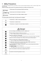
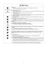
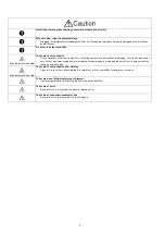
1 Safety Precautions
-----------------------------------------------
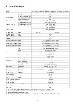
2 Specifications
-----------------------------------------------------
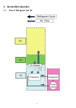
3 General/Introduction
--------------------------------------------
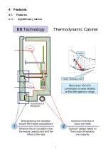
4 Features
-------------------------------------------------------------
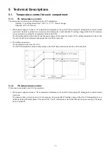
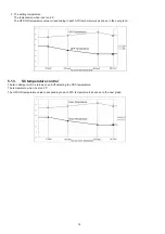
5 Technical Descriptions
----------------------------------------
6 Location of Controls and Components
------------------
7 Installation Instructions
---------------------------------------
8 Test Mode
----------------------------------------------------------
9 Service Mode
-----------------------------------------------------
10 Troubleshooting Guide
---------------------------------------
11 Disassembly and Assembly Instructions
---------------
12 Maintenance
------------------------------------------------------
13 Dimensions
-------------------------------------------------------
14 Schematic Diagram
--------------------------------------------
15 Exploded View and Replacement Parts List
-----------
Summary of Contents for NR-B32FX3
Page 6: ...6 3 General Introduction 3 1 Flow of Refrigerant And Air ...
Page 7: ...7 4 Features 4 1 Features 4 1 1 High Efficiency Cabinet ...
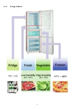
Page 8: ...8 4 1 2 Storage Solution ...
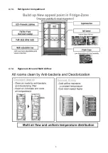
Page 9: ...9 4 1 3 Refrigerator Compartment 4 1 4 Hygiene Active and Multi Airflow ...
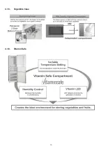
Page 10: ...10 4 1 5 Vegetable Case 4 1 6 Vitamin Safe ...
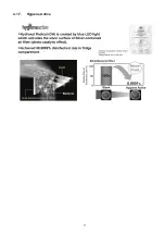
Page 11: ...11 4 1 7 Hygiene Active ...
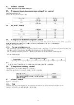
Page 18: ...18 6 2 Components ...
Page 19: ...19 7 Installation Instructions 7 1 Installation Instructions ...
Page 20: ...20 ...
Page 21: ...21 7 2 Setting the temperature ...
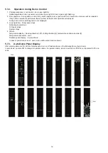
Page 22: ...22 7 3 Using the handy functions ...
Page 27: ...27 10 Troubleshooting Guide 10 1 FC and PC not cooling at all Compressor does not run ...
Page 28: ...28 10 2 PC is not cooling or poor cooling FC cooling condition is normal ...
Page 29: ...29 10 3 FC is poor cooling Compressor run ...
Page 30: ...30 10 4 VC is poor cooling or excessive cooling ...
Page 48: ...48 12 Maintenance ...
Page 49: ...49 ...
Page 50: ...50 ...
Page 51: ...51 13 Dimensions 13 1 Outside ...
Page 52: ...52 13 2 Inside ...