background image

© 2017 Panasonic Manufacturing Malaysia Berhad (6100-K).
Unauthorized copying and distribution is a violation of law.

ORDER NO. PMMA170535CE

Stand-alone Dishwasher

Model No.

NP-6R2MUQNZ-NZ

Destination:

New Zealand

Summary of Contents for NP-6R2MUQNZ-NZ

Page 1: ...017 Panasonic Manufacturing Malaysia Berhad 6100 K Unauthorized copying and distribution is a violation of law ORDER NO PMMA170535CE Stand alone Dishwasher Model No NP 6R2MUQNZ NZ Destination New Zealand ...

Page 2: ... Heater 20 5 5 1 Technical data 20 5 5 2 Possible cause of Malfunction 20 5 5 3 Inspect heater 20 5 6 Washing Pump 21 5 6 1 Possible cause of Malfunction 21 5 6 2 Technical data 21 5 6 3 Inspect Washing Pump 22 5 7 Pressure Switch 23 5 7 1 Working Principle 23 5 8 NTC 24 5 8 1 Working Principle 24 5 8 2 Inspect NTC 25 5 9 Flowmeter 26 5 9 1 Working Principle 26 5 9 2 Inspect Flowmeter 27 5 10 Safe...

Page 3: ...ecifications Model NP 6R2MUQNZ Power Source 220 240 V Wattage 1760 2100 W Frequency 50 Hz Water Pressure 0 04 1 0 MPa Capacity 12 Settings Dimensions L W H Approx 600 mm 600 mm 850 mm Nett Weight Approx 48 kg ...

Page 4: ... Display To show the remaining time and the state running state delay time and such Delay Time Remain Time or Error Codes indicator Water Supply indicator Indicates when shortage of water supply Extra Dry indicator 6 Programme indicators To show which programme has been chosen 7 Programme Selection button Press the button to select appropriate programme 8 Other indicators Rinse Aid indicator Indic...

Page 5: ...tom of machine 1 Disconnect power supply 2 Take out cutlery basket basket and filter system 3 Open the cover of bottom board 4 Remove the screws for fixing protecting box and open the protecting box cap 5 Disconnect the connector form PCB 6 Remove the screws securing the PCB to control panel 7 Remove the PCB 8 Reverse the above procedure to install ...

Page 6: ...rop 3 Remove the cover of the bottom board 4 Disconnect the 2 terminal lugs from the inlet valve 5 Pull out the valve a little then turn it in anti clockwise direction it to take it off 6 Remove the clamp and disconnect the inlet hose to air breaker from the water valve 7 Reverse above procedures to install ...

Page 7: ...sher If not wet the floor 2 Loosen the hooks and then remove bottom board Note You should first loosen the top hooks then the left and right hooks and be care do not break the hook 3 Label and disconnect the two terminal lugs from the drain pump 4 Turn the drain pump in anti clockwise direction to take it off 5 Reverse the above procedure to install ...

Page 8: ... and disconnect the power supply Note Make sure to remove remained water in the dishwasher If not wet the floor 2 Remove bottom board 3 Label and disconnect the terminals 4 Remove the 3 screws for fixing the heating element 5 Reverse above procedures to install ...

Page 9: ...p assembly from the dishwasher 7 Reverse above procedures to install 3 6 Access NTC 1 Remove bottom board 2 Remove two screws securing the NTC to sump shown in above picture 3 Take out NTC 4 Reverse the above procedure to install 3 7 Access Flowmeter 1 Remove the baseboard top panel and left side panel 2 Remove the plastic nut inside tub which secures the air breaker to tub Because flowmeter is in...

Page 10: ...lled out 3 Reverse the above procedure to assemble Mechanical Aquastop hose is connected to appliance just as universal water inlet hose 3 9 Access Diverter Valve 1 Disconnect power 2 Remove bottom board 3 Label and disconnect the 4 terminals 4 Remove 1 screw fastening the diverter valve to sump 5 Contrarotate the diverter valve to take it off 6 Reverse the above procedure to install ...

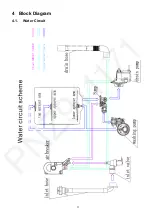
Page 11: ...11 4 Block Diagram 4 1 Water Circuit ...

Page 12: ... tub During this phase some of inlet water will be stored in the air breaker to be regenerating water Process of cycle washing indicated by blue route Cycle washing action is driven by washing pump motor Water can obtain the power during it passing through the working washing pump then be pumped into spray arm pass from spray arm nozzles over the dishes into sump where connect to washing pump and ...

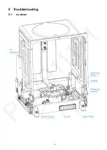
Page 13: ...13 5 Troubleshooting 5 1 Location ...

Page 14: ...14 1 Ensure there is no wire clamped by PCB Casing after you closed the PCB Box 2 Ensure the foam is already insert into the overflow assembly 3 Ensure all terminals is inserted firmly ...

Page 15: ...serted as the condition below 5 2 PCB Printed Circuit Board is the control center of dishwasher which receive and process signal from components send order to components and deal with the feedback information etc 5 2 1 View of PCB ...

Page 16: ...ontroller 5 3 2 Possible cause of Malfunction 1 The valve coil is broken so the valve can t open It will cause the E1 error 2 The filter is jammed so water can t enter It will cause the E1 error 3 The connector is loose so the valve can t open It will cause the E1 error 4 The valve pole is rusted or locked by dreg so the valve can t open or close It will cause the E1 or E4 error Mark Function HEAT...

Page 17: ...n first If the problem hasn t been solved by re connection we should replace the valve 4 If the resistance is OK we need to inspect the valve body 5 3 4 2 Check machine part 1 If the electric part is OK we need to check the machine part 2 Check the valve filter if the valve filter is blocked we need clear the residues 3 If the valve filter is clear and the valve can t inlet water check whether val...

Page 18: ...e drain pump can t work It will cause the E2 E4 or E1 error 2 The magnetism of motor rotor is weak so drain pump cannot work It will cause the E2 E4 or E1 error 3 The connector is loose so the drain pump can t work It will cause the E2 E4 or E1 error 4 The rotor is locked by residues so the drain can t work It will cause the E2 E4 or E1 error 5 The drain pump assembly rack is loose it will cause n...

Page 19: ...e we should check the connection first If the problem hasn t been solved by re connection we should replace the drain pump 4 If the resistance is OK but it also can t work maybe the magnetism is too weak so we need to replace the drain pump 5 4 4 2 Check the machine part 1 If the electric part is OK we need to check the machine part 2 Remove bottom board 3 If the non return valve is wrongly assemb...

Page 20: ...not work It will cause the E3 error 5 5 3 Inspect heater 1 Remove bottom board 2 With the door closed use the multi meter Ω shelf to measure resistance between the two terminals shown in above right picture the resistance is about 29Ω to 31Ω 3 If the measured resistance is not correct it means the heater coil or the thermostat is broken we should replace the heating element or the thermostat Nomin...

Page 21: ...ocked by residues so the wash pump can t work It will cause the E3 error 5 The drain pump assembly bracket is loose it will cause noise 6 If the machine hasn t been used for long time there is a possibility the wash pump can t starting 5 6 2 Technical data Models YXW48 2F 1 YXW48 2F Items Nominal voltage 220 240VAC 220 240VAC Frequency 50Hz 50Hz Resistance Main coil 159 4 10 Ω Main coil 120 10 7 Ω...

Page 22: ...irst If the problem hasn t been solved by re connection we would replace the washing pump 4 If the resistance is OK but it cannot work it maybe the capacitor weakly we need to replace the capacitor 5 6 3 2 Check the machine part 1 If the electric part is OK we need to check the machine part 2 Remove bottom board 3 Check the pump assembly if the bracket is loose it will bring the noise we need to t...

Page 23: ...witch consists of a moving diaphragm and disc which activate a change over contact The contact can be calibrated to trip and reset at the desired pressure levels The main application is to control the level of water in appliances May also provide flood protection ...

Page 24: ...24 5 8 NTC 5 8 1 Working Principle Negative Temperature Coefficient Thermistor is integrated into sump which is used for measuring temperature of water in the tub ...

Page 25: ...es RE and GND the normal resistance is shown in below table 3 If the resistance is not correct it means NTC circuit has a problem In this case we should check the connection first If the problem hasn t been solved by re connection we would replace the NTC NTC resistance table NTC 15 C 17 48KΩ 20 C 12 12KΩ 25 C 10KΩ 30 C 8 299KΩ 40 C 5 807KΩ 50 C 4 144KΩ 60 C 3 011KΩ 70 C 2 224KΩ 80 C 1 667KΩ 85 C ...

Page 26: ... Function of Flowmeter is measure how much water has entered in appliance it consists of impeller tongue tube and terminal etc When water pass through the flowmeter moving water can rotate magnetic impeller the tongue tube can sense the impeller s magnetic and send electronic pulses ...

Page 27: ...rm whether electrical pulse is sent out while water is passing through flowmeter or not 3 If there is continual electrical pulse the multi meter will send out sound de continually 4 if there is no electrical pulse the multi meter will not send sound In this case it means something wrong with flowmeter circuit We should check the connection first If the problem hasn t been solved by re connection w...

Page 28: ...layers If water leak and fill the air space between two layers the foaming material will expand and lock the hose In this situation the machine might set off E1 alarm Electronic Aquastop safety hose also has two layers But the difference from mechanical is that if water leak and flow on the bottom tray the flooding pressure switch on the tray will act the electromagnetic valve on the hose will cut...

Page 29: ...ybe moisture absorption of foaming material in mechanical device cause a self lock fault can t fill the water and this lock is non resettable 5 11 Diverter Valve 5 11 1 Work Principle Diverter also named alternating flow control valve is used to control the flow of water between the upper and lower spray arms and can also be used on some models to stop the flow of water to the upper spray arm on m...

Page 30: ...n and error code shown in above figure 5 12 2 Attention Priority level of E4 is the highest E4 operation is valid after other error operations have done When E4 operation has done all the others are invalid In test program E1 E3 E4 E6 E7 and E8 are valid Note ...

Page 31: ... the E4 would occur When E4 occurs the drain pump will run until flowmeter keep motionless for 2 minutes and all the other components will be stopped immediately At the same time the buzzer will alarm for 30 seconds and error 4 will be shown Note Priority level of E4 is the highest E4 operation is valid after other error operations have done When E4 operation has done all the others are invalid 5 ...

Page 32: ...32 5 13 Inspection 5 13 1 E1 tree ...

Page 33: ...33 5 13 2 E3 tree ...

Page 34: ...34 5 13 3 E4 tree ...

Page 35: ...s not been solved through all the inspection mentioned above maybe the PCB has a malfunction So replace PCB and test again Caution Because the real situation is unpredictable inspection trees mentioned in this manual are for reference only ...

Page 36: ...36 5 14 Troubleshooting ...

Page 37: ...37 ...

Page 38: ...38 ...

Page 39: ...39 ...

Page 40: ...40 ...

Reviews: