background image

© Panasonic Corporation 2016 Unauthorized copy-
ing and distribution is a violation of law.

Order No.APJWM160401CE
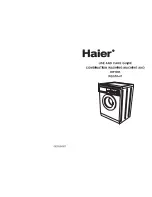
Washer Dryer

Model No.

NA-D106X1

Product Color :White 
Destination :Malaysia, Singapore, Thailand, Philippines 

TABLE OF CONTENTS

PAGE

PAGE

1 Safety Precautions

-----------------------------------------------

2

2 Specifications

-----------------------------------------------------

3

3 General/Introduction

--------------------------------------------

4

4 Control panel

------------------------------------------------------

5

5 Feature and Technical Description

-------------------------

6

6 Installation Instructions

----------------------------------------

9

7 Operating Instructions

-----------------------------------------

13

8 Disassembly Instructions and Adjustments

-----------

25

9 Wiring Diagram (OUTLINE) Drawing

----------------------

46

10 Troubleshooting Guide

----------------------------------------

48

11 External Diameter

-----------------------------------------------

56

12 Exploded View and Replacement Parts List

-----------

58

Summary of Contents for NA-D106X1

Page 1: ...d Philippines TABLE OF CONTENTS PAGE PAGE 1 Safety Precautions 2 2 Specifications 3 3 General Introduction 4 4 Control panel 5 5 Feature and Technical Description 6 6 Installation Instructions 9 7 Operating Instructions 13 8 Disassembly Instructions and Adjustments 25 9 Wiring Diagram OUTLINE Drawing 46 10 Troubleshooting Guide 48 11 External Diameter 56 12 Exploded View and Replacement Parts List...

Page 2: ...2 NA D106X1 1 Safety Precautions ...

Page 3: ...1 49 rpm Dram Dry revolutions 15 60 rpm Fan Dry revolutions 5 400 rpm Course Select Wash 7 course Cotton ECONAVI Hand Wash Intensive Bedding 40 C Soak Tub Clean Course Select Wash Dry 5 course Cotton ECONAVI Intensive Bedding 40 C Soak Course Select Dry only 2 course Cotton Bedding Individual setting Wash 1 30 min Individual setting Rinse 4 setting 1 time 2 times 3 times 4 times Individual setting...

Page 4: ...4 NA D106X1 3 General Introduction 3 1 Location of Components and Accessories ...

Page 5: ...5 NA D106X1 4 Control panel ...

Page 6: ...6 NA D106X1 5 Feature and Technical Description 5 1 Key feature 5 2 Foam maximize detergent power ...

Page 7: ...7 NA D106X1 5 3 Active Foam system 5 4 ECONAVI ...

Page 8: ...8 NA D106X1 5 5 Eco Drying system ...

Page 9: ...9 NA D106X1 6 Installation Instructions ...

Page 10: ...10 NA D106X1 ...

Page 11: ...11 NA D106X1 ...

Page 12: ...12 NA D106X1 ...

Page 13: ...13 NA D106X1 7 Operating Instructions 7 1 Door Lock and Child Lock ...

Page 14: ...14 NA D106X1 7 2 Laundry Procedure ...

Page 15: ...15 NA D106X1 7 3 Selecting the Program ...

Page 16: ...16 NA D106X1 7 4 How to Put in Detergent and Sofetner ...

Page 17: ...17 NA D106X1 7 5 Everyday Washing ...

Page 18: ...18 NA D106X1 7 6 Washing Options ...

Page 19: ...19 NA D106X1 ...

Page 20: ...20 NA D106X1 7 7 Drying ...

Page 21: ...21 NA D106X1 7 8 Maintenance ...

Page 22: ...22 NA D106X1 ...

Page 23: ...23 NA D106X1 7 9 Changing the Settings ...

Page 24: ...24 NA D106X1 7 10 Program Details ...

Page 25: ...ion part Do not touch rotating part high temperature part and surface of metal Be sure to replace with cable unit when any cable was snapped When a part of the cable unit was cut you must not do the connection repair It may be the cause of smoke ignition or receiving an electric shock Be sure to replace the whole cable unit when it is judged that connectors solderless terminals are connected inapp...

Page 26: ... is replaced remove the Top board as described in the procedure above and then disengage the hooks on the back side to replace 8 2 Lid sash Lead wire cover Controller Display side Door and Window cover 8 2 1 Replacement of Lid sash 1 Open the Door and disengage the hook on the Lid sash with the slotted screwdriver etc and slide the Lid sash upward to remove Same procedure on both sides While pushi...

Page 27: ...nnectors in the Lead wire cover blue and white 2 Remove the 3 mounting screws from the controller Display side 3 While pulling the lever of the Controller Display side upward slide it to the side to remove During assembly set the Lid sash at the end The Lid sash can be set only at the end Caution At the time of failure diagnosis and parts replacement please be sure to ground yourself Not doing so ...

Page 28: ...he hooks both sides and bottom securing the Window cover with the slotted screwdriver etc and remove the Window cover from the Door 8 3 Back panel V belt Pulley Motor 8 3 1 Replacement of Back panel 1 Remove the drain hose fastener from Back panel Be careful drain hose takes down may cause for drain water flow out 2 Remove 12 Back panel fixing screws on the back side of the main unit and remove th...

Page 29: ...ers with the hammer section when the HW 25K Flange nut remover tool is used 8 3 4 Replacement of Motor 1 After performing the procedures for Replacement of Back panel 8 3 1 and Replacement of V belt 8 3 2 remove the 4 Body joint plate B installation screws Earth cable fixing screw Clamping band 2 Motor left side connectors and 2 Motor fixing bolts and then remove the Motor from the Tank outer tub ...

Page 30: ...nsulation spacer fixing screws then remove insulation spacer from the Controller Power side 3 Remove the 4 Clamping bands from Controller Power side and disconnect all connectors Remove the 2 Controller Power side fixing screws The fan epuipped to the Controller Power side will be used to attach to the service Controller Power side during replacement Caution At the time of failure diagnosis and pa...

Page 31: ...xing screw and Clamping band then take the Cooling fan off 8 5 Damper 8 5 1 Replacement of Damper 1 After performing the procedures for Replacement of Panel A 8 1 1 Replacement of Back panel 8 3 1 and Replacement of Controller Power side 8 4 1 remove the Damper upper bolt Perform the Damper replacement work refer to Replacement of Controller Power side 8 4 1 until the state illustrated in the figu...

Page 32: ...hen disengage the 2 hooks on the Connector case B remove the Connector case B disconnect all connector wires inside the unit and remove the 1 Clamping band 3 After performing the procedure for Replacement of Back panel 8 3 1 stretch the Sub hose clamp securing the Discharge air hose to disconnect the Discharge air hose from the Tank outer tub In the figure shown below the hose clamp is removed and...

Page 33: ...the 2 Duct C fixing screws and remove it 7 Separation of the Fan case U from the Heater cover U Remove the 6 Clamping bands and the 3 Fan case U fixing screws Untie 4 lead wire fixing tapes Remove sensor and Discharge air hose Discharge air hose and the Fan case U are fixed by Clamping band Remove the 4 Fixing screws from the Terminal plate Remove the Fan case U and the Heater cover U ...

Page 34: ...ace it Once the Heater cover B is removed the Drying heater is exposed 8 7 3D sensor Water level sensor Nozzle and Detergent case A 8 7 1 Replacement of Water level sensor 1 After performing the procedures for Replacement of Panel A Dry filter Filter frame and Top board 8 1 remove the 1 Clamping band fixing the lead wire and 1 connector from Water level sensor and then remove the Air tube from the...

Page 35: ...d Top board 8 1 Replacement of Back panel 8 3 1 remove 4 Body support A mounting screws The Rinse case lid and Detergent case B will be used to attach to the service Nozzle and Detergent case A during replacement 2 Remove the 1 Nozzle fixing screw and 5 Clamping bands fixing the lead wire and then remove the Lead wire of the Water level sensor from 3 hooks 3 Lift the Nozzle up from the product and...

Page 36: ...Filter frame and Top board 8 1 Replacement of Lead wire cover 8 2 2 Replacement of Door 8 2 4 and Replacement of Controller Power side 8 4 1 Replacement of Panel B remove the Lid hinge cover and then remove the 8 Body B fixing screws 8 8 2 Replacement of Door lock switch 1 After performing the procedures for Replacement of Body B 8 8 1 remove the 1 Clamping band fixing the lead wire for the Door l...

Page 37: ...fter performing the procedures for Replacement of Body B 8 8 1 Replacement of Door lock switch 8 8 2 Replacement of Body band B 8 8 3 remove the 1 nozzle fixing screw refer to Replacement of Nozzle and Detergent case A 8 7 3 the 1 Clamping band fixing the lead wire for Door lock switch 8 Clamping bands fixing the Connector lead wire and 4 Body support D fixing screws The Lid hinge U can be replace...

Page 38: ...t of Body band B 8 8 3 and Replacement of Body band B front side back side 8 8 4 remove 13 Outer tub cover fixing screws and 3 bottom hose bands and then remove the Outer tub cover 8 10 Replacement of Drum unit 1 After performing the procedures for Replacement of Back panel V belt Pulley Motor etc 8 3 and Replacement of Wringer frame packing A Outer tub cover 8 9 pull out the Drum unit from the fr...

Page 39: ...nt of Circulation pump 1 Tilt the Controller Power side down refer to the Replacement of Damper 8 5 1 and remove 2 Circulation pump fixing screws and the Separator side of the Suction hose A 8 11 3 Replacement of Drain pump and Separetor After taking out Separator Assembly Separator Drain pump from Base remove Drain pump from Separator 1 Remove Service hose BU and Drain hose B from Separator 2 Rem...

Page 40: ...B in Replacement of Motor 8 3 4 in removed condition 2 Remove 2 nuts and remove the Earth terminal tightened with the nuts And remove the 2 Clamping bands to separate the connectors Please tighten the nut until the bolt extends to 14 mm 3 Tilt the body down to the left The body surface will touch the floor so be sure to use the Protective sheet before tilting it down 4 Remove 2 Clamping bands and ...

Page 41: ... connector and 1 Clamping band enables you to disassemble as shown in the figure below At this point the Sensor U and Heater switch plate can be removed At this point the Connector lead wire DU can be removed 7 Take the Heater off ...

Page 42: ... filter Filter frame and Top board 8 1 Replacement of Back panel 8 3 1 remove 4 Body support A mounting screws 2 Remove the 1 Nozzle fixing screw 5 Clamping bands fixing the lead wire and 2 Feeding valve connectors 3 Disengage 8 hooks on the Detergent case A and Nozzle 4 Remove the 2 Feeding valve fixing screws ...

Page 43: ... Sensor built in cord seal rubber Because the cord seal rubber is Sleeve you can take it easily 8 14 2 Replacement of Sensor U TH1 TH2 Go to the procedure for Replacement of Drying heater 8 6 2 1 Remove 3 Tapes and 2 Clamping bands 2 Remove the 6 Heater cover B fixing screws 3 Pull out 2 Sensor U TH1 TH2 built in cord seal rubbers to complete replacement Because the cord seal rubber is Sleeve you ...

Page 44: ...to the Sensor U as if to insert it into the hole Set the Dry filter as shown in the figure and perform the Service check D mode d1 8 14 3 Replacement of Discharge air hose and Exhaust air hose 1 When the Heater cover block is pulled out in the procedure 6 of Replacement of Fan case U 8 6 1 loosen the Sub hose clamp and then replace the Discharge air hose and Exhaust air hose Important Notice ...

Page 45: ...ter 1 After performing the procedures for Replacement of Back panel 8 3 1 remove 2 Body joint plate B fixing screws 2 Remove the 2 fixing screws securing the Chemical capacitor cover and Earth 3 Remove all Connectors 4 Take the Noise filter off ...

Page 46: ...46 NA D106X1 9 Wiring Diagram OUTLINE Drawing 9 1 NA D106X1 Wiring Diagram ...

Page 47: ...47 NA D106X1 9 2 Measure Input and Output value of Controller Power side ...

Page 48: ...l back to the Wash operation If controller have malfunction LED display indicate H05 2 C Spin operation check Operation check of Lid lock switch 7 Panel display Spin blinks LED display 7 7 minutes and then count down by one minute unit Locks the Lid performs Spin operation for 7 minutes Perform a electric continuity check of Lid lock switch When Lid lock switch OFF Times LED will be illuminate 3 D...

Page 49: ...tion sensor and memorized Then it performs the normal laundry amount detection After this detection standard value have memorized And then automatically Power Off If controller have malfunction LED display indicate H05 6 G1 LED display showing the last 10 errors detected E1 Panel display Wash and Spin blinks Initially LED display shows E1 Each time Rinse button is pressed the display changes in fo...

Page 50: ...g the operation contents in the last normal operation The contents of Normal operation is memorized when it has operated Wash Rinse and Spin E3 Panel display Wash and Spin blinks Initially LED display shows E3 Hold down Program button contents of last time operation setting shall be indicated Program Wash Dry Operation time and times for each process initial set remaining time Anti crease setting ...

Page 51: ...splayed cup LED is illuminate 10 P Initial display This part is not using this model P0 Panel display Rinse blinks Initially LED display shows P0 11 L Limit the maximum number of spin rotations L0 Panel display Spin and Dry blinks Initially LED display shows L0 This means no limitation for spin rotations Press once Rinse button display shows L1 This is preform of maximum number of spin rotation li...

Page 52: ...t switch in timer operation Door is open at the restart operation after Pause condition Door cannot be locked even if door lock signal is performed 3 times while the power is on The door is open Close the door The door is closed Check the deformation of lid hook Check the malfunction of lid lock switch And replace the lid or lid lock switch Close the door properly Press Start Pause button Cleared ...

Page 53: ...arm air thermistor TH3 Open condition more than 206k Short condition less than 96 Check the connector has not come off Replace the thermistor TH3 Power button off and on again H11 Malfunction of Exhaust air thermistor Open circuit or short circuit is caused in the Exhaust air thermistor TH1 Open condition more than 206k Short condition less than 96 Check the connector has not come off Replace the ...

Page 54: ...ration Check the clothes lean to one side Replace the 3D sensor Acceleration sensor Replace the motor Replace the controller unit Power side Power button off and on again H48 Malfunction of P C board thermistor Open circuit or short circuit is caused in the P C board thermistor Error data is memorized only Error is not displayed Replace the controller unit Power side Continued the operation and un...

Page 55: ...he demagnetization current detection circuit operates the specified times during the circulation pump operation Error data is memorized only Error is not displayed Check the operation of the circulation pump and replace it if necessary Replace the controller unit Power side Continued the operation and unnecessary to clear the error Circulation pump stop the operation Malfunction of Circulation pum...

Page 56: ...56 NA D106X1 11 External Diameter ...

Page 57: ...57 NA D106X1 ...

Page 58: ...58 NA D106X1 12 Exploded View and Replacement Parts List 12 1 Parts Exploded View Part A ...

Page 59: ...CKING 2 A22 AXW8E 9UU0 NOZZLE UNIT 1 A23 AXW2150 9SG0 SOAP CASE A 1 A24 AXW1250 9SG0 FEED HOSE A 1 A25 AXW245 6ML0 HOSE BAND 2 A26 AXW14A 9UU0 CONNECTOR LEAD WIRE UNIT 1 A27 AXW1619 9UU0 LOCK CASE UNIT 1 INCLUDES string for unlock A28 AXW1814 9SG0 CASE PACKING B 1 A29 AXW1317 9SG0 HEATER COVER B 1 A30 AXW264 9SL0 SUB HOSE CLAMP 1 A31 AXW314 9SG0 BLAST HOSE 1 A32 AXW6B 7JG0 TERMINAL PLATE UNIT 2 fo...

Page 60: ...60 NA D106X1 12 3 Parts Exploded View Part B ...

Page 61: ... AXW1096K9SH0 LID SASH A 1 Right side B09 AXW162K9SG0 WRINGER PORT FRAME 1 B10 AXW212 9SG0 WRINGER FRAME PACKING 1 B11 AXW172 9SH0 BODY TRIM B 1 B12 AXW114 9SG0 BODY SUPPORT D 1 B13 AXW11D 9SG0 LID HINGE UNIT 1 Upper B14 AXW11D 9SJ0 LID HINGE UNIT 1 Lower B15 AXW117 9SG0 BODY SUPPORT G 1 B16 AXW1194 9FX0 BODY LABEL 1 B17 AXW172 9SG0 BODY TRIM B 1 11 XTTAXW450 TAPPING SCREW 5 SUS410 L 12mm 12 XTBAX...

Page 62: ...62 NA D106X1 12 5 Parts Exploded View Part C ...

Page 63: ...0 CASING GASKET B 1 C16 AXW518 7PJ0 PULLEY THRUST WASHER A 1 C17 AXW502 8RT0 IMPELLER PULLEY UNIT 1 C18 AXW239 9SG0 SUB DRAIN HOSE A UNIT 1 C19 AXW6B 8RT0 TERMINAL PLATE UNIT 1 for Bubble sensing 1 C20 AXW1238 8RT0 WATERPROOFING COVER 1 C21 AXW13K 8RT0 HEATER HOLDER A UNIT 1 C22 AXW13C 7580 HEATER UNIT 1 Water Heater C23 AXW1328 6YZ0 THERMIC FUSE HOLDER A 1 C24 AXW24N 3910 SENSOR UNIT 1 Hot water ...

Page 64: ...64 NA D106X1 12 7 Parts Exploded View Part D ...

Page 65: ... 9SH0 SUSPENSION COMPLETE UNIT 1 Right front D31 AXW2331 9SG0 SUSPENSION COMPLETE UNIT 1 Right rear D32 AXW301K9UU0 BASE A 1 INCLUDES D33 and D34 D33 AXW337 6YZ0 ADJUSTABLE LEG BRACKET 2 D34 AXW3P 9SG0 LEG PLATE UNIT 2 D35 AXW343K7EP0 ADJUSTABLE THUMB 2 D36 AXW3D 7TE0 ADJUSTABLE LEG UNIT 2 Front Legs D37 AXW8H 9SG0 DC FAN MOTORS 1 Control Board cooling D38 AXW486 9SG0 INSULATION SPACER A 1 D39 AXW...

Page 66: ...66 NA D106X1 12 9 Parts Exploded View Part E ...

Page 67: ... E25 AXW110M8RT0 GRIP 8 Right and Left 4 pcs each E26 AXW170M8RT0 HOSE HANGER 2 Right and Left E27 AXW101K9SG0 BODY A 1 Left side E28 AXW101K9SH0 BODY A 1 Right side E29 AXW116 9SG0 BODY SUPPORT F 2 Front lower Right and Left E30 AXW1CK9SG0 PANEL A UNIT 1 E31 AXW1102 9UU0 DRAIN LABEL B 1 Malaysia Singapore Philippines E31 AXW1102 9UW0 DRAIN LABEL B 1 Thailand E32 AXW140K9UU0 PANEL B 1 Malaysia Sin...

Page 68: ...F04 AXW9004 9SG0 SIDE CUSHION 1 One set Right and Left F05 AXW9073 9SG0 UPPER CUSHION SUPPORT 2 Cardboard F06 AXW9069 6VD0 LID SHEET 1 F07 AXW9057 8RT0 ACCESSORY BAG 1 Small for E10 E24 and Screws F08 AXW9057 6NV0 ACCESSORY BAG 1 Large for E17 E18 E34 and F07 F09 AXW9057 7JG0 ACCESSORY BAG 1 for OPERATING INSTRUCTION F10 AXW9960 9UW0 ANTIFREEZE INSTRUCTION C 1 Thailand F12 AXW9060 7PJ0 POLYETHYLEN...

Reviews: