background image

© Panasonic Corporation 2015 Unauthorized copy-
ing and distribution is a violation of law.

Order No. VES1504005CE

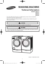
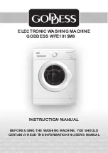
Drum Type Washing Machine

Model No.

NA-127VC6WFR

Model No.

NA-127VC6WES

Model No.

NA-127VC6WTA

Model No.

NA-127VC6WPL

Model No.

NA-127VC6WGN

Model No.

NA-127VC6WNR

Product Color : White
Destination     : France, Spain, Italy, Poland, Estonia, Lat-

via, Lithuania, Holland, Belgium, Czech, 
Hungary, Romania, Slovakia, Croatia, 
Serbia, Slovenia, Bosnia-Herzegovina, 
Sweden, Norway, Finland, Denmark

TABLE OF CONTENTS

PAGE

PAGE

1 Safety Precautions

-----------------------------------------------

2

2 Specifications

-----------------------------------------------------

3

3 Location of Controls and Components

-------------------

5

4 Installation Instructions

----------------------------------------

6

5 Operating Instructions

------------------------------------------

8

6 Test Mode

----------------------------------------------------------

10

7 Service Mode

-----------------------------------------------------

12

8 Troubleshooting Guide

----------------------------------------

13

9 Torque Values

----------------------------------------------------

14

10 Disassembly and Assembly Instructions

---------------

15

11 Component Specifications

-----------------------------------

25

12 Wiring Connection Diagram

---------------------------------

32

13 Exploded View and Replacement Parts List

-----------

34

Summary of Contents for NA-127VC6WES

Page 1: ...Lat via Lithuania Holland Belgium Czech Hungary Romania Slovakia Croatia Serbia Slovenia Bosnia Herzegovina Sweden Norway Finland Denmark TABLE OF CONTENTS PAGE PAGE 1 Safety Precautions 2 2 Specifications 3 3 Location of Controls and Components 5 4 Installation Instructions 6 5 Operating Instructions 8 6 Test Mode 10 7 Service Mode 12 8 Troubleshooting Guide 13 9 Torque Values 14 10 Disassembly a...

Page 2: ...2 ...

Page 3: ...195 kWh annum Water Consumption 10346 L annum Noise Level Wash 58 dBA Spin 74 dBA Control Panel LCD Display Wash Programs 15 settings Spin Speed Setting 7 setting Dimensions Height 84 5 cm Width 59 7 cm Depth 52 7 cm Door Opening Large door opening Delay Time Setting Yes Colour White Water Protection Overflow Protection Other Features Child Lock Packaging Shrink package 2 2 Name Plate ...

Page 4: ...4 2 3 Dimension in millimetres NA 127VC6 ...

Page 5: ...5 3 Location of Controls and Components ...

Page 6: ...the plastic adjustment nut again by rotating it upwards against the base of the cabinet 7 Never put cartons wooden blocks or similar materials under the machine to balance irregularities of the floor 3 Pull out the screws and rubber washers 4 1 3 Electrical Connection 1 Washing machine requires a 50Hz supply of 220 240Volts 2 A special earthed plug has been attached to the supply cord of washing m...

Page 7: ...ng on tap completely 6 Make sure that water inlet hoses can not become folded damaged stretched or crushed when the washing machine is in its final position 7 Mount the water inlet hose to a threaded water tap 4 1 5 Drain Connection 1 Make sure that water inlet hoses are not folded twisted crushed or stretched 2 The drain hose should be mounted at a minimum height of 60 cm and a maximum height of ...

Page 8: ...erature Display I8 Extra Rinse Symbol SS2 7 Segment LCD for Spin Speed Display I9 Easy Ironing Symbol SS3 7 Segment LCD for Remaining Time I10 Eco Mode Symbol I1 Child Lock Symbol I11 Speed Mode Symbol I2 Door Lock Symbol I12 Cold Wash Symbol I3 Drain Phase Symbol I13 Temperature Sign I4 Spin Phase Symbol I14 Program Proceeding Zone I5 Rinse Phase Symbol Slow Blink ON 0 5 sec OFF 0 5 sec ON 0 5 se...

Page 9: ...9 5 2 Program Details ...

Page 10: ...hild Lock is active Deactivation Press SW7 for 5 seconds The Child Lock Symbol will disappear on LCD displayupon deactivation 6 Test Mode 6 1 Autotest Set PR to program 3 Colours While pressing SW5 Extra Rinse change position of the PR from third program to second Cotton Prewash and release SW5 Autotest starts ...

Page 11: ...n the water level NTC check Heather resistance Pump EPS measurement End Visualization 65 55 35 15 50 60 5 10 25 40 AUTOTEST If temperature value is outside the range then it means NTC is detecting the temperature in a wrong way and heating step will be skipped EPS measurement The frequency value should be between 46 04Hz 43 40Hz It checks the EPS and if it OK it continues the autotest if it is NOK...

Page 12: ...heating Heater will be on max 8 minutes after this 8 minutes if the temp doesn t change more than 2 C then it will give NTC failure E05 Or if the NTC connection is broken then it should give again E05 NTC failure At the end of heating SAU visualization should make slow blink to indicate that the step is over Note If user changes the selector position machine will do what is defined for the new sel...

Page 13: ... the desired status The door is not shut properly Shut the door properly You should hear the click Child lock is active See section 5 3 Machine does not receive water Water tap is closed Open water tap The water inlet hose may be bent Check the water inlet hose The water inlet hose is obstructed Clean the filters of water inlet hose The water inlet filter is obstructed Clean the valve inlet filter...

Page 14: ...etergents which do not dissolve in water may stick to clothes as white stains By calibrating machine for Rinsing program make an additional rinsing or eliminate the stains After drying with the help of a brush There are grey stains on the clothes These stains may be caused by oil cream or ointment In the next washing operation use the maximum detergent amount declared by the detergent producer The...

Page 15: ...the back Push the top plate back and pull it up 10 2 Door 1 2 Remove two screws that fix the door by using T25 tool Pull the door up 3 4 Remove screws that fix the door group Put the door outside plastic with helping screwdriver 5 6 Remove the door inside plastic Remove six screws that fix the door hinge T25 ...

Page 16: ...he small size screw driver Pull the tub bellows seal Remove the tub bellows seal body fixing spring 10 4 Detergent Drawer 1 2 Gently pull the detergent drawer While pressing siphon cover keep pulling drawer to remove it 10 5 Control Panel 1 2 Remove the screw which fixes the control panel to the front panel Remove two screws fixing control panel ...

Page 17: ... plastic by depressing the taps with the help of a screwdriver 3 4 Remove the card out off panel Remove the sockets on the card 5 6 After releasing sockets remove PCB box from its housing around the box Disassemble the PCD box and its cover 7 8 Remove the PCB card by depressing the taps that fix it Remove the connector that fix the LCD screen ...

Page 18: ...e taps by using a screwdriver 10 7 Front Panel 1 2 Remove the screw fixing the front panel at the bottom Remove two screws fixing the door lock 3 4 Remove the tub bellows seal 5 6 Remove two screws fixing front panel to body Remove the screw fixing twinjet elbow 7 8 Pull front panel up Remove front panel ...

Page 19: ...tub bellow hose by releasing the holder extensions of bellow hose Unplug connectors from feed valve 3 4 Slightly turn the feed valve counter clockwise to remove Remove the detergent drawer housing assembly 10 10 Power Cable Group and EMI Filter 1 2 Remove the five conectors that is connected to the EMI filter Remove two screws fixing EMI filter ...

Page 20: ...r 10 11 Electronic Pressure Switch EPS 1 2 Unplug EPS connector Pull EPS up 10 12 Door Lock 3 1 Remove clamp from EPS hose Unplug door lock connector 10 13 Drain Pump 1 2 Remove clamp holding drain hose by using a plier Remove clamp fixing tub outlet hose ...

Page 21: ...g drain pump 10 14 Front Counterweight 1 2 Remove three screws on the front counterweight Wrench size 13 mm Gently pull counterweight out 10 15 Heater 1 2 Unplug heater connectors Remove nut 8 mm fixing the heater 3 Pull heater out gently holding both sides ...

Page 22: ...seal and gasket body fixing spring together and pull them out 10 17 Transport Screw 1 2 Remove four transport screws Hold the transport screw and pull it out 10 18 Upper Counterweight 1 2 Remove two screws fixing the upper counterweight by using box wrench size 13 mm Hold and carry upper counterweight out ...

Page 23: ...acket Remove the washing group carrying it out through front side 10 20 Shock Absorber Pin 10 21 Driven Pulley 1 1 Remove shock absorber pins squeezing the ratchet by a pliers Remove the belt rotating the driven pulley 10 22 Driven Pulley 1 1 Remove the bolt at the center of pulley by tucking a wooden bar avoids rotation Remove pulley ...

Page 24: ...r up 10 24 Tub 1 2 Remove tub inlet bellow hose loosening the clamp squeezing it by using a pliers Remove screw holding EPS reservoir 3 4 Remove tub outlet bellowed hose loosening screwed clamp Remove 19 screws around tub using box wrench size 8 mm 5 6 Remove front tub Remove drum ...

Page 25: ...ominal voltage 220 240 V Nominal current 0 28 A 10 Nominal power 37 W Frequency 50 Hz Resistor coil 136 Ω 5 Water flow 17 L min to 1 m height Therma protector YES Testing component Check the resistance value on the component with multimeter as shown below Resistance value should be between 131 141 Ω You can determine the ohm value of drain pump by measuring from the socket with two blue cables con...

Page 26: ... type Tubular heating element with NTC sensor Nominal voltage 230 V Nominal power 2000 W 5 Resistance 26 4 5 Ω Ther al fuse 2 sided Testing component Check the resistance value on the component with multimeter as shown below Resistance value should be between 26 4 5 Ω You can determine the ohm value of resistance by measuring from the socket with grey and brown cables referring to X6 on the electr...

Page 27: ...5 12 5 30 9 4 10 2 35 7 8 8 3 40 6 4 6 9 45 5 4 5 7 Tem C R min kΩ R max kΩ 50 4 5 4 7 55 3 8 3 9 60 3 2 3 3 65 2 7 2 8 70 2 3 2 4 75 1 9 2 80 1 7 1 8 85 1 4 1 5 90 1 2 1 3 95 1 1 1 1 100 0 9 1 NTC Resistance vs NTC Temperature Testing component Check the resistance value on the component with multimeter as shown below You can determine the ohm value by measuring from the socket with two black cab...

Page 28: ...e 0 02 1 Mpa Testing component Check the resistance value on the component with multimeter as shown below Valve water flow rate should be between 6 8 L min Each valve coil resistance values should be between 3 3 4 2 kΩ You can determine the resistance value of the main wash valve by measuring from the large socket which has one blue one black and two white cables as shown in the figure below refer...

Page 29: ...ic field The water level is regulated according to the frequency changes of the spring by electronic card EPS Testing component Push the door lock slider with screwdriver Select the 1st program and start the machine Unplug power cable when as soon as water intake finishes and drum begins to rotate Check the water level inside the drum with ruler It should be 10 cm 1 ...

Page 30: ... red cable at 6th position in the large socket refer to section 12 Wiring Connection Diagram as shown on right figure For resistance values refer to the table below Stator Resistance Control Check the motor stator terminals on the motor socket with multimeter as shown in the picture You can determine the ohm value by measuring from the black cable at 18th and brown cable at 8th position in the lar...

Page 31: ...washing cycle the PTC bimetal assembly will cool down and after minimum 60 sec considering previous power supply of 30 sec min and T 20 C the door will be unlocked and thus can be opened In case the door is closed when current comes back the PTC bimetal assembly will heat again the slider lock will lock the contact will close and the program will continue from where it stopped Door lock Technical ...

Reviews: