background image

© Panasonic Corporation 201

2

 Unauthorized copy-

ing and distribution is a violation of law.

Order No. VES1

212

00

8

CE

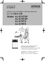
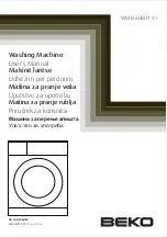
Drum Type Washing Machine

Model No.

NA-148VB3

WRU

Model No.

NA-12

7

VB3

WRU

Product Color : White
Destination     : 

Russia,Ukraine,


Kazakhstan


TABLE OF CONTENTS

PAGE

PAGE

1 Safety Precautions

-----------------------------------------------

3

2 Specifications

-----------------------------------------------------

4

2.1. Product Specifications------------------------------------ 4
2.2. Name Plate-------------------------------------------------- 4

3 Technical Descriptions

-----------------------------------------

5

3.1. Twinjet Information ---------------------------------------- 5

4 Location of Controls and Components

-------------------

6

5 Installation Instructions

----------------------------------------

7

5.1. Moving and Installing ------------------------------------- 7
5.2. Detergent Box Group ------------------------------------- 8

6 Operating Instructions

------------------------------------------

9

6.1. LCD Screen, Function Buttons & Knobs ------------ 9
6.2. Program List ------------------------------------------------ 9
6.3. Program Details-------------------------------------------10
6.4. Program Details with Half Load Defection ---------10
6.5. Child Lock --------------------------------------------------11

7 Test Mode

----------------------------------------------------------

12

7.1. Autotest----------------------------------------------------- 12

8 Service Mode

-----------------------------------------------------

14

8.1. Service Autotest ------------------------------------------ 14
8.2. Failure Codes --------------------------------------------- 15

9 Troubleshooting Guide

---------------------------------------

16

10 Disassembly and Assembly Instructions

---------------

17

10.1. Torque Values--------------------------------------------- 17
10.2. Top Plate --------------------------------------------------- 18
10.3. Door --------------------------------------------------------- 18
10.4. Spring Wire ------------------------------------------------ 20
10.5. Detergent Drawer ---------------------------------------- 20
10.6. Control Panel---------------------------------------------- 21
10.7. Kick Plate -------------------------------------------------- 22
10.8. Front Panel ------------------------------------------------ 22
10.9. Upper Support Bracket --------------------------------- 24

10.10. Detergent Drawer Housing ---------------------------- 24

10.11. Power Cable Group and Parasite Filter ------------ 25

Summary of Contents for NA-127VB3WRU

Page 1: ...onents 6 5 Installation Instructions 7 5 1 Moving and Installing 7 5 2 Detergent Box Group 8 6 Operating Instructions 9 6 1 LCD Screen Function Buttons Knobs 9 6 2 Program List 9 6 3 Program Details 10 6 4 Program Details with Half Load Defection 10 6 5 Child Lock 11 7 Test Mode 12 7 1 Autotest 12 8 Service Mode 14 8 1 Service Autotest 14 8 2 Failure Codes 15 9 Troubleshooting Guide 16 10 Disassem...

Page 2: ...ain Pump 33 11 2 Circulation Pump 34 11 3 Resistance 35 11 4 NTC 36 11 5 Valve 37 11 6 Electronic Pressure Switch EPS 38 11 7 Motor For NA 127VB3 and NA 147VB3 39 11 8 Motor For NA 128VB3 and NA 148VB3 40 11 9 Door Lock 41 12 Dimensions 43 13 Wiring Connection Diagram 44 13 1 Wiring Diagram NA 127VB3 and NA 147VB3 44 13 2 Wiring Diagram NA 128VB3 and NA 148VB3 46 14 Exploded View and Replacement P...

Page 3: ...3 1 Safety Precautions ...

Page 4: ...splay E Type LED display E Type LED display E Type Wash Programs 15 settings 15 settings 15 settings 15 settings Spin Speed Setting 6 setting 6 setting 6 setting 6 setting Dimensions Height 85 cm 85 cm 85 cm 85 cm Width 60 cm 60 cm 60 cm 60 cm Depth 58 cm 58 cm 53 cm 53 cm Door Opening Large door opening Large door opening Large door opening Large door opening Delay Start Yes Yes Yes Yes Color Whi...

Page 5: ...ecreased by 15 2 Twinjet system is valid for all programs except spin and drain mode The system does not function during Water inlet heating spinning and drain phases 3 Even with a large load of 8 kg the washing machine will have minimum energy consumption by the help of Twinjet system 4 Washing machines with Twinjet system are very environ ment friendly by having maximum washing performance with ...

Page 6: ...6 4 Location of Controls and Components ...

Page 7: ...t non slippery firm surface Any suspended floor must be suitably strengthened 3 You can adjust the level of machine using its feet 4 First loosen the plastic adjustment nut away from the cabinet base 5 Change the level by adjusting the feet upwards or down wards 6 After level has been reached tighten the plastic adjust ment nut again by rotating it upwards against the base of the cabinet 7 Never p...

Page 8: ...r leakage by turning on tap completely 6 Make sure that water inlet hoses can not become folded damaged stretched or crushed when the washing machine is in its final position 7 Mount the water inlet hose to a 3 4 inch threaded water tap 5 1 5 Drain Connection 1 Make sure that water inlet hoses are not folded twisted crushed or stretched 2 The drain hose should be mounted at a minimum height of 60 ...

Page 9: ... Temperature Function Button Led LD3 Delay Time Function Button Led LD4 Extra Rinse Function Button Led LD5 Spin Phase Led LD6 Rinse Phase Led LD7 Wash Phase Led LD8 Child Lock Activation Led LD9 Door Lock Led LD10 Lack Of Water Indication Led LD11 Pump Failure Indication Led Knob Position Program Pos1 Cotton Pos2 Cotton PW Pos3 Cotton Eco Pos4 Coulors Pos5 Easy care Pos6 Wool Pos7 Rinse Pos8 Drai...

Page 10: ... 28 57 Rinse WIT WIT 36 0 05 58 Spin 15 0 08 Drain 3 0 02 Programmes Temperature Available Temperature Program Duration min Energy kwh Water Consumption L Cotton 40 Cold 90 120 0 92 60 Cotton Eco 40 Cold 90 138 0 98 69 Cotton PreWash 60 Cold 60 200 0 80 45 Easy Care 40 Cold 60 85 0 61 47 Coulors 40 Cold 40 100 1 00 52 Wool 30 Cold 40 40 0 11 45 Quick 40 Cold 60 68 0 48 38 Rapid 15 30 Cold 30 15 0 ...

Page 11: ...ion 1 Press the fourth function button for 4 5 seconds 2 The Child Lock Symbol is appeared on the LCD display Deactivation 1 Press the fourth function button for 4 5 seconds 2 The Child Lock Symbol is deleted on the LCD display ...

Page 12: ...1 Autotest 1 After selecting spin speed to max select the program 3 Cotton Eco 2 While pressing Extra Rinse button change position of the third to second and release the Extra Rinse button imme diately 3 Autotest starts ...

Page 13: ...13 ...

Page 14: ... Prewash will be PUMP ON Temperature will be measured if it is higher than 50 C it should take 60 sec cooling water and then make Drain 5 sec At the end of pump activation SAU visualization should make slow blink to indicate that the step is over Step 3 Selector Cotton Eco will be 15 minutes test program So time for selector position 3 is 15 minutes At the end of 15 minutes test program END is vis...

Page 15: ... is unlocked during programme E01 Yes Yes Lack of water E02 Yes Yes Pump failure E03 Yes Yes Overflow E04 Yes Yes NTC or Heater Failure E05 No Yes Motor Failure 1 Tachometer open short circuit or motor connector is disconnected E06 No Yes Motor Failure 2 triac short circuit E08 No Yes Out of voltage No No Electronic Pressure Sensor E10 No Yes ...

Page 16: ...lanced manner Excessive foam in the detergent drawer Too much detergent has been used Press the start pause button In order to stop the foam dilute one table spoon of softener in half liter of water and pour it in the detergent drawer Press the start pause button after 5 10 minutes Arrange the amount of the detergent properly in the next washing process Wrong detergent has been used Use only the d...

Page 17: ...817 2 43 2 70 2 97 Front Panel Drop Fixing Plastic ISO 7049 ST 4 2x16 35008931 2 50 2 70 2 90 Mechanic Control Panel Program Knob Supporting Sheet MV1 SCREW 3 5X9 PAN HEAD WITH COLLAR CROSS RECESS 35007387 0 50 1 00 1 00 Mechanic Control Panel Program Knob Supporting Sheet MV2 SCREW 3 5X9 PAN HEAD WITH COLLAR CROSS RECESS 35007387 0 50 1 00 1 00 Detergent Drawer Control Panel Assembly SCREW 4X14 P...

Page 18: ...1 Remove two screws that fix the top plate at the back 2 Push the top plate back and pull it up 10 3 Door 1 Remove two screws that fix the door by using the T25 2 Pull the door up 3 Remove screws that fix the door group ...

Page 19: ...own in the picture 5 Remove the door inside plastic as it is shown in the pic ture 6 Remove six screws that fix the door hinge as it is shown in the picture 7 Remove the door handle as it is shown in the picture 8 Remove the door handle pin as it is shown in the pictures ...

Page 20: ...ire fixing the tub bellows seal by using the small size screwdriver Pull the tub bellows seal as it is shown in the picture 2 Remove the tub bellows seal body fixing spring 10 5 Detergent Drawer 1 Remove the detergent drawer and pull it up carefully ...

Page 21: ... the control panel to the front panel 2 Remove three screws fixing the control panel 3 Pull the control panel up 4 Remove connectors as it is shown in the picture 5 Remove electronic card cover as it is shown in the pic tures by using small screwdriver ...

Page 22: ... picture 2 Remove two screws fixing the kick plate 3 Pull the kick plate left and push it down 10 8 Front Panel 1 Remove two screws fixing the front panel at the bottom as it is shown in the picture by using T25 2 Remove two screws fixing the door lock as it is shown in the pictures ...

Page 23: ...g front panel at the upper as it is shown in the picture 5 Remove twinjet t elbow screw fixing front panel at the upper as it is shown in the picture 6 Remove twinjet t elbow fixing front panel at the upper as it is shown in the picture 7 Remove the front panel as it is shown in the pictures ...

Page 24: ...icture 3 Remove detergent drawer group two clips fixing the upper support bracket as it is shown in the picture 10 10 Detergent Drawer Housing 1 Remove the tub seal clamp by using the pliers which is attached to the detergent drawer housing 2 Remove the four connectors that is connected to the feed valve as it is shown in the picture 3 Turn the feed valve counter clockwise slightly to remove ...

Page 25: ... and Para site Filter 1 Remove the five connectors that is connected to the para site filter 2 Remove two screws fixing the parasite filter 3 Pull the power cable group up as it is shown in the pic ture 4 Remove parasite filter fixing body group as it is shown in the picture ...

Page 26: ...S upward to remove as it is shown in the pic ture 3 Remove the EPS hose handcuffs and EPS hose as it is shown in the picture 10 13 Door Lock 1 Remove the connector that is connected to the door lock 10 14 Pump Motor 1 Remove pipe clip that fixes the drain hose 2 Remove pipe clip fixing the tub outlet hose ...

Page 27: ...s fixing the pump motor 5 Remove pipe clip fixing the twinjet hose 10 15 Front Counterweight 1 Remove four screws fixing the front counterweight on the front Box wrench size 13 mm 2 Pull the counterweight back 10 16 Heater 1 Remove the four connectors that is connected to the heater ...

Page 28: ... 3 Hold the heater and pull it out 10 17 Twinjet System 1 Remove pipe clip fixing the twinjet hose 2 Remove the two twinjet hoses from the gasket 3 Remove screw fixing the circulation pump using T20 4 After lay down the washer on its rear side and press the pawl inward ...

Page 29: ...tion pump 10 18 Tub Bellows Seal 1 Remove the tub gasket clip by using small screwdriver 2 Hold the tub bellows seal and gasket body fixing spring together and pull them up 10 19 Transport Screw 1 Remove four transport screws box wrench size 10 mm 2 Hold the transport screw and pull it out ...

Page 30: ...rench size 13 mm 2 Remove the upper counterweight 10 21 Washing Group 1 Remove the connector that is connected to the motor 2 Cut the five lead wire holders as shown the pictures 3 Remove the four screws fixing the spring hanger sheet iron 4 Remove the washing group as it is shown in the picture ...

Page 31: ...Remove the belt as it is shown the picture 10 24 Driven Pulley 1 Remove the screw fixing driven pulley it is shown the pic ture By using T40 2 Remove the driven pulley it is shown the picture 10 25 Motor 1 Remove the four screws fastening the motor under the tub by using T40 2 Pull the motor up for disassembly ...

Page 32: ...ose 10 27 Pressure Switch Hose Group 1 Remove screw fixing the pressure switch water reservoir 2 Remove the tub exit with bellow hose with ball by using box wrench size 10 mm 10 28 Tub 1 Remove twenty four screws fixing tub using box wrench size 8 mm 10 29 Drum 1 Remove the drum ...

Page 33: ...nent with multimeter as shown in belows figures Resistance value should be between 131 141 Ω Checking the component 11 1 3 Component Controlling By Con nection Measurement You can determine the ohm value by measuring from the blue cable at 2nd and blue cable at 11th position in the large socket refer to 13 Wiring Connection Diagram as shown in belows figures Resistance value should be between 131 ...

Page 34: ...timeter as shown Resistance value should be between 160 180 Ω Checking the component 11 2 3 Component Controlling By Con nection Measurement You can determine the ohm value by measuring from the red cable at 5th and red cable at 12th position in the small socket refer to 13 Wiring Connection Diagram as shown in belows figures Resistance value should be between 160 180 Ω Nominal voltage 220 240 V F...

Page 35: ...ctures Checking the component 11 3 3 Component Controlling By Con nection Measurement You can determine the ohm value by measuring from the grey cable at 13th and brown cable at 4th position in the small socket refer to 13 Wiring Connection Diagram as shown in belows figures Resistance value should be between 23 27 Ohm Kind of heating Tubular heating element with NTC sensor Nominal voltage 230 V N...

Page 36: ...ent Controlling By Con nection Measurement You can determine the ohm value by measuring from the black cable at 3th and black cable at 11th position in the small socket refer to 13 Wiring Connection Diagram as shown in belows figures NTC resistance value varies depending on temperature Tem C R min kΩ R max kΩ 10 54 9 62 6 5 43 0 48 6 0 33 9 38 1 5 27 0 30 1 10 21 6 23 9 15 17 4 19 1 20 14 1 15 4 2...

Page 37: ...hould be between 3 3 4 2 kohm Checking the component 11 5 3 Component Controlling By Con nection Measurement You can determine the ohm value of the main wash valve by measuring from the blue cable at 5th and white cable at 15th position or the pre wash valve by measuring from the black cable at 14th and white cable at 15th position in the large socket refer to 13 Wiring Connection Diagram as shown...

Page 38: ...omagnetic field The water level is regulated by the frequency which is controlled by the PCB and changes according to the movement of the nucleus part 11 6 2 Checking of Component 1 Push the door lock slider with screwdriver 2 Select the 1st program and start the machine 3 Cut off the energy input when the water intake finishes and drum begins to rotate 4 Check the water level inside the drum with...

Page 39: ...olling By Connec tion Measurement Tacho You can determine the ohm value by measuring from the pink cable at 16th and red cable at 6th position in the large socket refer to 13 Wiring Connection Diagram as shown in belows figures For resistance values refer to the table 11 7 2 Resistance Controlling By Connec tion Measurement Stator You can determine the ohm value by measuring from the brown cable a...

Page 40: ...y Connec tion Measurement Tacho You can determine the ohm value by measuring from the pink cable at 16th and red cable at 6th position in the large socket refer to 13 Wiring Connection Diagram as shown in belows figures For resistance values refer to the table 11 8 2 Resistance Controlling By Connec tion Measurement Stator You can determine the ohm value by measuring from the brown cable at 8th an...

Page 41: ...Bimetal In Case of Lack of Electric Energy In case of lack of electric energy during a washing cycle the PTC bimetal assembly will cool down and after minimum 60 sec considering previous power supply of 30 sec min and T 20 C the door will be unlocked and thus can be opened In case the door is closed when current comes back the PTC bimetal assembly will heat again the slider lock will lock the cont...

Page 42: ...t Controlling By Con nection Measurement This socket shows the connection between terminal 3 4 See wiring diagram above The resistance read from terminal 3 4 is the resistance of PTC overload plus resistance of sole noid ...

Page 43: ...43 12 Dimensions ...

Page 44: ...44 13 Wiring Connection Diagram 13 1 Wiring Diagram NA 127VB3 and NA 147VB3 ...

Page 45: ...45 ...

Page 46: ...46 13 2 Wiring Diagram NA 128VB3 and NA 148VB3 ...

Page 47: ...47 ...

Page 48: ...48 14 Exploded View and Replacement Part List 14 1 Control Panel Parts 14 1 1 Exploded View Control Panel Parts ...

Page 49: ...400 DETERGENT DRAWER COVER 1 AXW1BV 77250 NA 148VB3 CONTROL PANEL 1 AXW2DV 77150 NA 127VB3 401 CONTROL PANEL 1 AXW2DV 77230 NA 148VB3 408 PCB FOIL 1 AXW1FS 7092 410 DISPLAY FOIL 1 AXW1FS 7315 ELECTRONIC CARD GR 1 AXW24V 68093 NA 127VB3 412 ELECTRONIC CARD GR 1 AXW24V 68095 NA 148VB3 413 CABLE AND FUSE FOLDER COVER 1 AXW2CF 55340 415 SELECTION BUTTONS 1 AXW146 55331 416 FUSE 1 AXW1FS 13553 420 LIGH...

Page 50: ... PANEL GROUP AXW1BB 42790 1 4 PLINTH GROUP AXW22S 23758 1 5 ADJUSTABLE FEET GR AXW31 00778 4 9 HOUSING FRAM BELLOW CLIP PHT AXW1Z 08309 1 10 DOOR LOCK AXW1619 3597 1 20 WATER ENTRY HOSE GROUP AXW12C 14423 1 WITHOUT AQUASTOP 22 PLINTH AXW130 23756 1 23 PLINTH COVER AXW140 23757 1 U 24 UPPER SUPPORT BRACKET AXW1US 50726 1 892 SCREW TT M4X8 PAN HEAD CR 3 FOR ASIA 893 BOTTOM PLATE 1 FOR ASIA 894 BOTTO...

Page 51: ...51 14 3 Washing Group Parts 14 3 1 Exploded View Washing Group Parts ...

Page 52: ...W212 08555 1 120 FRONT CONCRETE WEIGHT AXW1231 3571 1 AXWRG1 12964 1 NA 127VB3 121 RESISTANCE GR AXWRG1 09949 1 NA 148VB3 999 NTC TEMP SENSOR AXW1EV 35970 1 AXWRG1 12964 1 NA 127VB3 899 RESISTANCE WITHOUT NTC AXWRG1 09949 1 NA 148VB3 115 RESISTANCE FIXING WIRE AXWRFW 14491 1 AXWSA1 01197 2 NA 127VB3 104 SHOCK ABSORBER AXWSA1 05034 2 NA 148VB3 213 TUB EXIT BELLOW HOSE WITH BALL AXW1250 4954 1 124 C...

Page 53: ... 925 TWIN JET NOZZLE AXWTJN 25574 2 931 TWIN JET HOSE_H NO 2 AXWTJH 25991 1 927 TWIN JET CBL HOSE HLDR PLASTIC AXWTJC 25867 5 928 HANDCUFFS O26 8 AXW2HC 09578 1 929 PUMP PROTECTION FOIL 3 AXW1PF 04693 1 930 TWIN JET HOSE_N NO 1 AXWTJH 25194 1 118 TUB BELLOWS SEAL AXW212 25995 1 926 CIRCULATION PUMP AXW8CP 06191 1 285 PUMP GR FLTR TH PROTECT AXW8FT 06391 1 446 ISO 7049 ST 4 2x13 TYPE 2 AXWSS6 07273...

Page 54: ...5590 1 202 SIPHON COVER AXW1PV 05600 1 U 228 PLASTIC HOSE CLAMP AXW1PH 04189 4 AXW1VD 04536 1 NA 127VB3 207 VALVE DETERGENT BOX HOSE AXW1VD 04537 1 NA 148VB3 AXW1VD 07796 1 NA 127VB3 208 VALVE DETERGENT BOX HOSE AXW1VD 07797 1 NA 148VB3 209 VALVE TWO EXIT AXW1VT 13042 1 AXW21D 60571 1 NA 127VB3 270 DETERGENT BOX GROUP AXW21D 60574 1 NA 148VB3 AXW31D 60572 1 NA 127VB3 275 DETERGENT BOX GROUP HOSE A...

Page 55: ...rts List REF NO PART NAME CODE QTY REMARKS 210 TUB EXIT BELLOW HOSE BALL AXW12520 0200 1 211 PRESSURE SWITCH HOSE AXW1PS 19319 1 212 PRESSURE SW WATER RESERVOIR AXW1PS 20089 1 213 TUB EXIT WITH BELLOW HOSE AXW1250 4954 1 234 HOSE HANDCUFFS O32 7 AXW1HC 07366 1 244 HOSE HANDCUFFS AXW1HC 08991 1 295 PRESSURE SW H GR PYT BALL SYST AXW2PS 29739 1 ...

Page 56: ...56 14 7 Body Group Parts 14 7 1 Exploded View Body Group Parts ...

Page 57: ... 2 235 DRAIN HOSE HOLDING PLS AXW1HC 14270 4 239 POWER CORD GROUP AXW4A 17511 1 EU TYPE 222 PRESSURE SW MOUNTING CLIP AXW1HC 22768 1 238 SPEED CONTROL HOLE STOPPER AXW1SC 16338 1 AXW2CB 13278 1 NA 127VB3 296 CBL GR AXW2CB 13276 1 NA 148VB3 242 TRANSPORT SCREW PLASTIC A II P AXW1TS 60786 4 243 TRANSPORT SCREW PLASTIC B II P AXW1TS 60789 4 240 TRANSPORT SCREW 2 AXWSB4 08363 4 241 PLAIN WASHER 10 5X4...

Page 58: ...23907 4 33 DOOR HINGE SUPPORT SHEET AXW192 08152 1 410 SCR 4X12PAN HE W CLR UNDER HE AXWSB8 13513 6 18 INNER DOOR PLS INSERT PART AXW1DP 55348 1 17 DOOR HOOK II METAL AXW1DH 08931 1 15 HOOK SPRING AXW1HS 07443 1 16 HANDLE SPRING AXW1HS 14985 1 7 DOOR GLASS AXW1GD 03771 1 27 DOOR HANDLE TONGUE PIN AXW1DH 07434 3 14 DOOR HANDLE AXW1DH 55346 1 32 OUTER DOOR PLS INNER FRAME AXW1DS 55345 1 31 FRONT DOO...

Page 59: ...59 14 9 Accessories 14 9 1 Accessories View 996 997 998 994 ...

Page 60: ...90LD 9158 1 997 DRAIN HOSE COAT RACK AXW90HC 0601 1 998 TRANSPORT SCREW STOPPER AXW1TS 14437 1 1 Ref No 988 includes program label in following languages Norwegian Swedish Finnish and Danish 2 Ref No 989 includes program label in following languages Dutch French Serbian Turkish Polish Czech Hungarian Slovakian Romanian Crotaian Bulgarian and Slovenian 14 10 Packaging Group Parts 14 10 1 Exploded V...

Page 61: ...61 ...

Page 62: ...056956 1 NA 148VB3 902 REAR STYROFOAM LEFT AXWPV 277830 1 903 REAR STYROFOAM RIGHT AXWPV 277820 1 904 FRONT STYRF L SIGMA PLUS 2 AXWPV 277810 1 905 FRONT STYRF R SIGMA PLUS 2 AXWPV 280760 1 906 CORNER CARDBOARD AXWPV 002040 1 907 TUB SUPPORT STYROFOAM AXWPV 053000 1 908 PORTHOLE PRO STYROFOAM AXWPV 244940 1 PACKAGE CARTON 7K AXWPV 651930 1 NA 127VB3 909 PACKAGE CARTON 8K AXWPV 651940 1 NA 148VB3 ...

Reviews: