background image

2018/6

AQCTB02E    

201806-E

Contact to :

• Printed colors may be slightly different from the actual products.

• Specifications and design of the products are subject to change without notice for the product improvement. 

Repair

URL

Consult to the dealer from whom you have purchased this product for details of repair work. 

When the product is incorporated to the machine you have purchased, consult to the machine 

manufacturer or its dealer.
• Technical information of this product (Operating Instructions, CAD data, Inquiries) can be downloaded 

  from the following web site.

  <industrial.panasonic.com/ac/e/>

COM

PA

CT

 A

C GEA

RED M
OT

O

R

1-1 Morofuku 7-chome, Daito, Osaka 574-0044, Japan

Tel : +81-72-871-1212

Fax: +81-72-870-3151

Panasonic Corporation, 
Automotive & Industrial Systems Company,
Electromechanical Control Business Division, 
Motor Business Unit

The contents of this catalog apply 

to the products as of June 2018.

This product is for industrial equipment. Don't use this product at general household.

 • Important Notes on exporting this product or equipment containing this product;
  If the end-user or application of this product is related to military affairs or weapons, its export may be controlled by “Foreign 

Exchange and Foreign Trade Control Law” of Japan where export license will be required before product can be exported from 
Japan.

 • This product is designed and manufactured for use in General Purpose Industrial Equipment and it is not intended to be used 

in equipment or system that may cause personal injury or death.

 • All servicing such as installation, wiring, operation, maintenance and etc., should be performed by qualified personnel only.
 • Tighten mounting screws with an adequate torque by taking into consideration strength of the screws and the characteristics of 

material to which the product will be mounted. Over tightening can damage the screw and/or material; under tightening can 

result in loosening. 

    *Example: apply 2.7 N·m – 3.3 N·m torque when tightening steel screw (M5) to steel surface.
 • Install safety equipment to prevent serious accidents or loss that is expected in case of failure of this product.
 • Consult us before using this product under such special conditions and environments as nuclear energy control, aerospace, 

transportation, medical equipment, various safety equipments or equipments which require a lesser air contamination.

 • We have been making the best effort to ensure the highest quality of our products, however, some applications with 

exceptionally large external noise disturbance and static electricity, or failure in input power, wiring and components may result 
in unexpected action. It is highly recommended that you make a fail-safe design and secure the safety in the operative range.

 • If the motor shaft is not electrically grounded, it may cause an electrolytic corrosion to the bearing, depending on the condition 

of the machine and its mounting environment, and may result in the bearing noise. Checking and verification by customer is 

required.

 • Failure of this product depending on its content may generate smoke of about one cigarette. Take this into consideration when 

the application of the machine is clean room related.

 • Please be careful when using the product in an environment with high concentrations of sulfur or sulfuric gases, as sulfuration 

can lead to disconnection from the chip resistor or a poor contact connection. 

 • Do not input a supply voltage which significantly exceeds the rated range to the power supply of this product. Failure to heed 

this caution may lead to damage of the internal parts, causing smoke and/or fire and other troubles.

 • The user is responsible for matching between machine and components in terms of configuration, dimensions, life expectancy, 

characteristics, when installing the machine or changing specification of the machine. The user is also responsible for 
complying with applicable laws and regulations.

 • Manufacturer’s warranty will be invalid if the product has been used outside its stated specifications. 
 • Component parts are subject to minor change to improve performance.
 • Read and observe the instruction manual to ensure correct use of the product.

Compact AC Geared Motor

2018.06

industrial.panasonic.com/ac/e/

Summary of Contents for M41A1G4L

Page 1: ...all safety equipment to prevent serious accidents or loss that is expected in case of failure of this product Consult us before using this product under such special conditions and environments as nuclear energy control aerospace transportation medical equipment various safety equipments or equipments which require a lesser air contamination We have been making the best effort to ensure the highes...

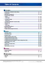
Page 2: ...rder A 31 Terminology Motor A 32 Gear head A 34 Handling instructions A 35 Motor selection A 48 Safety standard approved motor A 59 Motors Induction motor B 1 Reversible motor B 63 3 phase motor B 125 Electromagnetic brake motor B 167 Variable speed induction motor B 223 Variable speed reversible motor B 267 Variable speed electromagnetic brake single phase motor B 309 Variable speed unit motor B ...

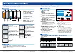
Page 3: ...n Torque oz in 2 4 6 M61X3G4L 60mm 2 36inch 3W 26 1 02 33 1 30 32 1 26 ø8h7 ø0 31h7 ø25 ø0 98 7 0 28 10 0 39 6 0 24 60 mm sq 2 36 inch sq ø70 ø 2 76 4 ø4 5 ø0 18 12 0 47 Gear head MX6G BA g MX6G B g MX6G MA g MX6G M g Index Each series is color coded Motors Controls Classification is made in terms of function Size and output Indicates the size and output shown on the page Footer Indicates the page...

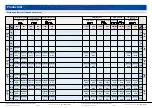
Page 4: ...4Y M9RZ60GK4Y M9RZ90GK4Y B 104 B 108 B 112 B 116 Induction Size Voltage V Output Leadwire type Sealed connector type 1 W 3 W 3 W 4 W 6 W 10 W 15 W 15 W 20 W 25 W 40 W 60 W 90 W 42mm sq 1 65inch sq 60mm sq 2 36inch sq 80mm sq 3 15inch sq 90mm sq 3 54inch sq 70mm sq 2 76inch sq Reversible Leadwire type Sealed connector type 200 220 200 220 200 220 100 200 100 200 M8MX25G4Y M9MX40G4Y M9MZ60G4Y M9MZ90...

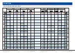
Page 5: ...tic brake single phase C B variable speed induction Leadwire type 1 W 3 W 3 W 4 W 6 W 10 W 15 W 15 W 20 W 25 W 40 W 60 W 90 W Variable speed unit US series 100 200 100 200 100 200 B 352 B 354 B 356 B 358 B 360 B 362 B 352 B 354 B 356 B 358 B 360 B 362 B 364 B 366 B 368 B 370 B 364 B 366 B 368 B 370 B 388 B 390 B 392 B 394 B 396 B 398 B 388 B 390 B 392 B 394 B 396 B 398 200 220 200 220 B 372 B 374 ...

Page 6: ...YS M9RZ90SK4YS B 124 B 124 B 124 B 124 Induction Leadwire type Sealed connector type 1 W 3 W 3 W 4 W 6 W 10 W 15 W 15 W 20 W 25 W 40 W 60 W 90 W Reversible Leadwire type Sealed connector type 200 220 200 220 200 220 100 200 100 200 M8MX25S4YS M9MX40S4YS M9MZ60S4YS M9MZ90S4YS B 164 B 164 B 164 B 164 M8MX25SK4YS M9MX40SK4YS M9MZ60SK4YS M9MZ90SK4YS B 165 B 165 B 165 B 165 M8MX25SB4YS M9MX40SB4YS M9MZ...

Page 7: ...91Z90G4YG B 16 B 22 B 28 B 32 B 36 B 40 M61X6G4GG M71X15G4GG M81X25G4GG M91X40G4GG B 16 B 22 B 28 B 32 B 36 B 40 M81X25GK4LG M91X40GK4LG M91Z60GK4LG M91Z90GK4LG B 44 B 48 B 52 B 56 M81X25GK4DG M91X40GK4DG M91Z60GK4DG M91Z90GK4DG B 44 B 48 B 52 B 56 M81X25GK4YG M91X40GK4YG M91Z60GK4YG M91Z90GK4YG B 44 B 48 B 52 B 56 M81X25GK4GG M91X40GK4GG B 44 B 48 B 52 B 56 Induction Leadwire type 1 W 3 W 3 W 4 W...

Page 8: ...9MZ90GK4YGA M8MX25GK4CGA M9MX40GK4CGA M9MZ60GK4CGA M9MZ90GK4CGA M8MX25GB4YGA M9MX40GB4YGA M9MZ60GB4YGA M9MZ90GB4YGA B 204 B 208 B 212 B 216 110 115 200 B 180 B 184 B 188 B 192 B 196 B 200 B 180 B 184 B 188 B 192 B 196 B 200 3 phase Leadwire type Sealed connector type Electromagnetic brake single phase Leadwire type Leadwire type Page Page Page Page Page Page Page Page Page Page Page Page Page Page...

Page 9: ... B 278 B 284 B 290 B 294 B 298 B 302 M6RX6GV4GG M7RX15GV4GG M8RX25GV4GG M9RX40GV4GG M9RZ60GV4GG M9RZ90GV4GG B 278 B 284 B 290 B 294 B 298 B 302 Leadwire type 1 W 3 W 3 W 4 W 6 W 10 W 15 W 15 W 20 W 25 W 40 W 60 W 90 W Variable speed induction Variable speed reversible Leadwire type Page Page Page Page Page Page Page Page Page Page Page Page Page Page Page Page Size Size The models with a model num...

Page 10: ...0 W 60 W 90 W 1 W 3 W 3 W 4 W 6 W 10 W 15 W 15 W 20 W 25 W 40 W 60 W 90 W Leadwire type Sealed connector type M6RX6S4LG M7RX15S4LG M8RX25S4LG M9RX40S4LG M9RZ60S4LG M9RZ90S4LG M6RX6S4DG M7RX15S4DG M8RX25S4DG M9RX40S4DG M9RZ60S4DG M9RZ90S4DG M6RX6S4YG M7RX15S4YG M8RX25S4YG M9RX40S4YG M9RZ60S4YG M9RZ90S4YG M6RX6S4GG M7RX15S4GG M8RX25S4GG M9RX40S4GG M9RZ60S4GG M9RZ90S4GG M8RX25SK4LG M9RX40SK4LG M9RZ60...

Page 11: ...G M81X40S2GG M81X60S2GG M91X60S2GG M91Z90S2GG M91ZA5S2GG M61X6SV4LGA M71X15SV4LGA M81X25SV4LGA M91X40SV4LGA M91Z60SV4LGA M91Z90SV4LGA M61X6SV4DGA M71X15SV4DGA M81X25SV4DGA M91X40SV4DGA M91Z60SV4DGA M91Z90SV4DGA M61X6SV4YGA M71X15SV4YGA M81X25SV4YGA M91X40SV4YGA M91Z60SV4YGA M91Z90SV4YGA M61X6SV4GGA M71X15SV4GGA M81X25SV4GGA M91X40SV4GGA M6RX6SV4LGA M7RX15SV4LGA M8RX25SV4LGA M9RX40SV4LGA M9RZ60SV4L...

Page 12: ... Hinge 1 3 1 3 6 1 5 1 6 1 7 5 1 9 1 10 1 12 5 1 15 1 18 1 20 1 25 1 30 1 36 1 50 1 60 1 75 1 90 1 100 1 120 1 150 1 180 1 3 1 3 6 1 5 1 6 1 7 5 1 9 1 10 1 12 5 1 15 1 18 1 20 1 25 1 30 1 361 50 1 60 1 75 1 90 1 100 1 120 1 150 1 180 1 3 1 3 6 1 5 1 6 1 7 5 1 9 1 10 1 12 5 1 15 1 18 1 20 1 25 1 30 1 36 1 50 1 60 1 75 1 90 1 100 1 120 1 150 1 180 1 3 1 3 6 1 5 1 6 1 7 5 1 9 1 10 1 12 5 1 15 1 18 1 ...

Page 13: ... 5 1 6 1 7 5 1 9 1 10 1 12 5 1 15 1 18 1 20 1 25 1 30 1 36 1 50 1 60 1 75 1 90 1 100 1 120 1 150 1 180 1 200 Size 40 W Common to 60 W 90 W 42 mm sq 1 65 inch sq 60 mm sq 2 36 inch sq 70 mm sq 2 76 inch sq 80 mm sq 3 15 inch sq 90mm sq 3 54inch sq 60 mm sq 2 36 inch sq 70 mm sq 2 76 inch sq 80 mm sq 3 15 inch sq MX6G3BU MX6G180BU MX7G3BU MX7G180BU MX8G3BU MX8G180BU MX9G3BU MX9G180BU MZ9G3BU MZ9G200...

Page 14: ... 4 pole Single phase 2 pole 3 phase Single phase 3 phase Single phase Single phase Single phase Single phase 3 phase Single phase 3 phase Single phase Single phase Single phase Single phase Single phase Continuous run not required One directional rotation only Single phase 3 phase Single phase 3 phase 3 phase Continuous run required Normal reverse rotation Continuous run required Continuous run no...

Page 15: ...ight angle gear Decimal gear for C B motor Inch sized U S A Permissible torque 19 6 N m 173 lb in Right angle gear Decimal gear for C B motor Inch sized U S A Permissible torque 29 4 N m 260 lb in Ball bearing Metal Ball bearing Ball bearing Ball bearing Ball bearing Metal Ball bearing Ball bearing Ball bearing Ball bearing Metal Ball bearing Ball bearing Ball bearing Ball bearing Metal Ball beari...

Page 16: ...ater and mechanical damage Motor live parts are enclosed in drip proof and dust proof terminal box Compact design earth terminal and sealed connector for easier piping IP54 Pinion shaft Induction motor 25 W to 90 W 3 phase motor 25 W to 90 W IP40 Pinion shaft Reversible motor 25 W to 90 W Round shaft Induction motor 60 W to 90 W Reversible motor 60 W to 90 W 3 phase motor 60 W to 90 W IP20 Round s...

Page 17: ... motor Electromagnetic brake motor Wide range of input supply Single phase 100 V to 230 V 48 mm 48 mm 1 89 inch 1 89 inch square DIN type 11 pin Unit motor B 323 C 21 Quick connection of motor and controller Simplified operation with volume type control US Single phase 100 V 200 V Contacting type C 30 Basic type of instant control Single phase 100 V 200 V 3 phase 200 V Rectangular type 8 pin Brake...

Page 18: ...me rating A time rating is used to express the time during which the motor can normally output the rated power Continuous rating indicates that the motor can provide the rated power during this period The short time rating indicates that the motor will reliably operate to produce the rated output for the relatively short time specified Rated output An optimum output performance which the motor can...

Page 19: ... described in This efficiency is determined by the bearing friction of the gear tooth and resistance of lubricating oil In general this efficiency is approx 90 per stage of the gear For example 81 for 2 stage configuration and then decreases to 75 70 65 as the number of stages increases In the case of metal gear head this efficiency is approx 85 per stage of the gear Maximum permissible torque Max...

Page 20: ...e the product is subjected to dust water oil coolant splash explosive flammable or corrosive gas H2S SO2 NO2 Cl2 etc 4 In the case of international standard approved model When using a pinion shaft motor use it with the gear head attached When using a round shaft motor provide a means so that the heat dissipates over the machine and equipment Temperature rise cooling curve and running condition Fi...

Page 21: ...unning for the reversible motors Horizontal axis shows the running time t1 and vertical axis shows the pause time t2 The motor can be operated for a continuous intermittent running in the range of these lines In this figure each line represents as below 1 Motor alone running at 60 Hz 2 Motor alone running at 50 Hz 3 Motor with gear head running at 60 Hz 4 Motor with gear head running at 50 Hz For ...

Page 22: ...s Connection Connections or joints of motor leadwires power cable and capacitor should be made using soldering connector or crimping terminal whichever suitable and should be covered with appropriate insulating material Clamp the motor leadwires on the equipment at stable area so that the leadwires are kept stress free Earth terminal screw Leadwires Loosely bundle leadwires Earth terminal screw M4...

Page 23: ...ll the product in the control board to make its terminal block inaccessible Securely install and fix the equipment to prevent bodily injury or fire in case of earthquake Provide emergency stop circuit externally for instantaneous interruption of operation and power supply Install overcurrent protection device ground fault circuit interrupter overtemperature protecting device and emergency stop dev...

Page 24: ...electric shock or malfunction Failure to heed this instruction will result in electric shock personal injury or fire Locked motor will cause fire electric shock or malfunction Failure to heed these precautions cause bodily injury Failure to heed this instruction will result in personal injury electric shock fire malfunction or damage Failure to heed this instruction will result in fire electric sh...

Page 25: ...e and life are not secured As indicated on the nameplate 10 C to 40 C 90 C or below on frame surface ambient temperature 40 C No increase in abnormal sound or noise level No abnormal vibration Flow of cooling air is not disturbed by dust and powder No oil or grease from joint to gear head or from output shaft Connect the 500 V megger across motor lead and earth terminal The reading should be 50 MΩ...

Page 26: ...prox 0 05 to 0 2 g Gravitational acceleration 9 8 m s2 P Lead of ball screw m 1 2π T P F μW kgf m F External force kgf W Weight of load kgf μ Friction coefficient of sliding surfaces approx 0 05 to 0 2 P Lead of ball screw m 1 2π SI units Gravitational system of units T D μWg N m D Diameter of drum m W Mass kg g Gravitational acceleration 9 8 m s2 μ Friction coefficient 1 2 T D μW kgf m D Diameter...

Page 27: ...tational acceleration 9 8 m s2 Angular acceleration rad s2 In the case of induction motor torque generated at the starting varies depending on the speed Therefore an average acceleration torque is generally used which is the averaged torque from the starting and the constant speed A necessary average acceleration torque TA to accelerate the load inertia of J kg cm2 GD2 kgf cm2 up to a speed n r mi...

Page 28: ...83 0 755 0 755 2 187 3 554 3 554 0 755 2 187 3 554 3 554 2 60 No of phases Size Output W Rotor inertia Average acceleration torque Permissible load inertia at motor shaft J kg cm2 N m kgf cm J kg cm2 Single phase Reversible 60 mm sq 2 36 inch sq 4 0 113 0 452 50 Hz 60 Hz 0 0402 0 0392 0 41 0 40 0 125 0 50 6 0 173 0 691 50 Hz 60 Hz 0 0539 0 0549 0 55 0 56 0 125 0 50 42 mm sq 1 65 inch sq 1 0 029 0 ...

Page 29: ...ulation GD2 Flywheel effect calculation Disk Hollow circular cylinder Sphere Cube Slender round bar D D d D c b a L 2 L 2 D J Inertia calculation GD2 Flywheel effect calculation Equivalent all inertia on axis a J J1 2 J2 kg cm2 n1 Speed of axis a r min n2 Speed of axis b r min J1 J of axis a kg cm2 J2 J of axis b kg cm2 Equivalent all flywheel effect on axis a GD2 GD21 2 GD22 kgf cm2 n1 Speed of a...

Page 30: ...le direction This load is generated when the gear head is coupled to the machine using a chain belt etc but not when the gear head is directly connected to the coupling As shown in the right figure the permissible value is determined based on the load applied to the L 2 position of the output shaft The thrust load is defined as a load applied to the output shaft in the axial direction Because the ...

Page 31: ...or design is used The CSA standard is a necessary requirement for exporting to Canada It is possible to put a c UL mark on products inspected and approved by UL in accordance with the CSA standard in addition to the UL standard Products bearing this c UL mark are regarded as products conforming to CSA standard and therefore can be sold in Canada UL standard on motor UL1004 1 motor Provisions conce...

Page 32: ... V 3 phase motor please connect to be applied voltage to AC250 V from AC100 V between the lines of thermal protector blue blue Wiring example of 2 pole 4 pole 3 phase motor 200 V 220 V 230 V Wiring example of 4 pole 3 phase motor with electromagnetic brake 200 V 220 V 230 V Wiring example of 4 pole 3 phase motor with electromagnetic brake Connect between 3 phase power supply R and neutral point N ...

Page 33: ... thermal protector International standard approved Japanese version Variable speed motor 90 W open 130 5 C open 120 5 C close 90 15 C close 77 15 C When the thermal protector is operating the temperature of the coil is slightly higher than the operating temperature shown above Test It has passed a lock test of 18 days straight Impedance protected motor It is applied to the motors with mounting sur...

Reviews: