background image

Operating Instructions

Model No.

KXF-3V3C

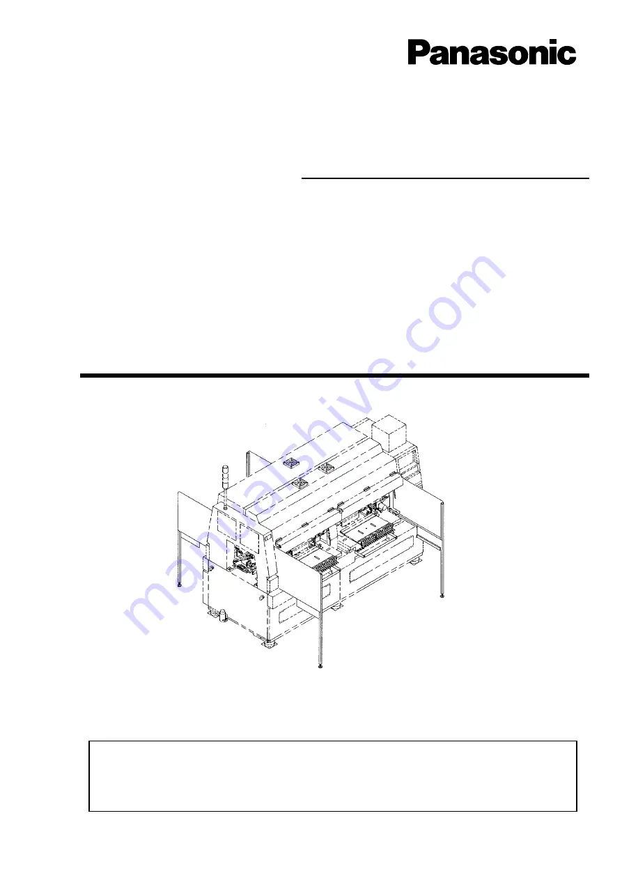
Thank you for purchasing CM95R, the multi-functional chip mounter.
Before placing the machine in service, be sure to read the instruction manual for
proper usage.
After that, store it carefully and it if necessary.

3V3C-E-MMDB-0001

Multi-functional Chip Mounter CM95R

Maintenance Manual

(1/2)

Summary of Contents for KXF-3V3C

Page 1: ...ing CM95R the multi functional chip mounter Before placing the machine in service be sure to read the instruction manual for proper usage After that store it carefully and it if necessary 3V3C E MMDB 0001 Multi functional Chip Mounter CM95R Maintenance Manual 1 2 ...

Page 2: ......

Page 3: ...LOW ANY PERSON WHO HAS NOT RECEIVED SPECIAL TRAINING TO OPERATE THE MACHINE The machine may be operated improperly and injure you Either carry out training by yourself or consult the manufacturer WARNING 3V3C E MMD00 B01 00 ...

Page 4: ...y of the units This manual is for machine maintenance and describes the daily checks adjustment and replacement of consumable parts Troubleshooting is also included This manual is for the machine operators and describes the operat ing procedure precautions and information which are necessary for safe and effective operation This manual is for the data programmers and describes the methods for crea...

Page 5: ...6 Page 5 1 2 3 4 SAFETY PRECAUTIONS MAINTENANCE INSPECTION ERROR MESSAGES MACHINE PARAMETER TEACHING LOAD ARRANGEMENT APPENDIX I O MAP DAIAGRAM 2 2 APPENDIX DAIAGRAM Refer to the following pages for detailed contents 1 2 ...

Page 6: ...17 1 2 7 Conveyor 1 21 1 2 8 Board Recognition 1 22 1 2 9 Chip Recognition Part 1 23 1 2 10 Cut Offset Unit 1 25 1 2 11 Tape Unit 1 31 1 2 12 Pre centering Unit 1 32 1 2 13 Laser Unit 1 33 1 2 14 Control Unit 1 34 1 2 15 Tray Feeder Matrix Table 1 35 1 2 16 Tray Feeder Lifter 1 36 1 2 17 Tray Feeder Transfer Head 1 37 1 2 18 Tray Feeder Pallet Changer 1 38 1 2 19 Multi tray Feeder X Y Unit 1 39 1 ...

Page 7: ...ery Replacement 2 ST Name MT20F SL 1 63 1 5 1 Type and Use 1 63 1 5 2 Battery Setting Position 1 64 1 5 3 Replacing Battery on SCMSEC 1 64 1 6 Procedures for Replacing Consumables Used on the Vacuum Pump 1 65 1 6 1 Periodic Checks 1 65 1 6 2 List of Consumables 1 65 1 6 3 Procedures for Replacing Consumables 1 66 1 7 Changing the Board Transfer Belts 2 68 2 ERROR MESSAGES 2 1 Messages for Floppy D...

Page 8: ...n Operating Method of the Displayed Screen Typical Example 2 22 2 3 1 Nozzle Exchange Fault Detected Error code 006 2 23 2 3 2 Cover Open 2 24 2 3 3 Area Sensor Detected 2 24 2 3 4 Front Interlock Error 2 25 2 3 5 Driver Overheat Error 2 25 2 3 6 Nozzle Interlock Sensor Intercepted 2 25 2 3 7 Stop Due to Cover Open or Area Sensor 2 25 2 3 8 Chip Recognition Fault 2 26 2 3 9 Pick up Fault 2 27 2 3 ...

Page 9: ...Origin Offset Outside Range Error Code 034 2 54 2 4 13 Holder Pin and Conveyor Interfered Error Code 036 2 55 2 4 14 Communication Error with Recognition Device A stage Error Code 042 2 55 2 4 15 Communication Error with Recognition Device B stage Error Code 043 2 55 2 4 16 Temp Compensation 2 56 2 4 17 Height Sensor Error 2 56 2 4 18 Nozzle Eccentric Error 2 56 2 4 19 R axis Heat Crr Err R axis H...

Page 10: ...gnition Error 2 73 2 5 2 Mounting Point Recognition Error 2 75 2 5 3 Laser Recognition Error 2 76 2 5 4 Board Transfer Error 2 77 2 5 5 Chip Recognition Error 2 78 2 6 Messages for Selftest Screen of Multi tray Feeder 2 79 2 6 1 Emergency Stop Switch NG 2 79 2 6 2 Servo Switch NG 2 79 2 6 3 Nozzle Floating Detection NG 2 80 2 6 4 Pallet Pinch Detection Pick up Side NG 2 80 2 6 5 Pallet Pinch Detec...

Page 11: ...Side 2 100 2 8 6 Pallet Clamp Pick up Side Time Over 2 100 2 8 7 Interference on Exchange Open Section 2 100 2 8 8 Interference on the Upper Part of Pallet 2 100 2 8 9 Pallet Conveyance Time Over 2 101 2 8 10 Lifter Axis Belt Is Broken 2 101 2 8 11 Magazine Is Not Clamped 2 102 2 8 12 Air Pressure Down 2 102 2 8 13 Head Trouble 2 103 2 8 14 Transmission Error with CM95 2 103 2 8 15 Pallet Return F...

Page 12: ... 3 11 Substage 1 Position Temporary Positioning Stage Teaching 3 71 3 12 Substage 2 Position Teaching 3 75 3 13 Fixed Camera Position Deformed Parts Recognizing Unit Teaching 3 80 3 13 1 Adjustment of Fixed Camera Setting 3 80 3 13 2 Head Height Adjustment of Fixed Camera during Recognition 3 85 3 13 3 Fixed Camera Position Teaching 3 91 3 14 Eject Conveyor Position Teaching 3 96 3 15 Height Senso...

Page 13: ... 4 1 4 2 Load List CM95R M 4 3 4 2 1 Photo Sensor List NZ PH 4 3 4 2 2 Limit Switch List LS 4 5 4 2 3 Air Pressure Switch List PSW VSW 4 6 4 2 4 Solenoid SOL VL 4 6 4 2 5 Motor List M 4 8 4 2 6 Chip Height Sensor 4 8 4 3 Load Arrangement MT20F SL 4 9 4 4 Load List MT20F SL 4 11 4 4 1 Photo Sensor List PH 4 11 4 4 2 Limit Switch List LS 4 12 4 4 3 Solenoid VL 4 12 INDEX ...

Page 14: ...1 CPU BOX C 2 POWER BOX C 3 VACUUM PUMP BOX D JUNCTION BOARD DIAGRAM E SET UP DIAGRAM F MT20F SL F 1 I O MAP F 2 SYSTEM BLOCK DIAGRAM F 3 SYSTEM WIRING DIAGRAM F 4 LOAD WIRING DIAGRAM F 5 CONTROL BOX DIAGRAM F 6 JUNCTION BOARD DIAGRAM F 7 SET UP DIAGRAM G SINGLE TRAY FEEDER G 1 I O MAP G 2 ELECTRIC CIRCUIT DIAGRAM G 3 SET UP DIAGRAM APPENDIX ...

Page 15: ...Page 15 CONTENTS H NG DISCHARGE CONVEYOR UNIT H 1 ELECTRIC CIRCUIT DIAGRAM I PNEUMATIC CIRCUIT DIAGRAM 3V3C E MMD00 A03 00 ...

Page 16: ...Page 16 CONTENTS 3V3C E MMD00 A03 01 MEMO ...

Page 17: ... in which there is imminent danger of serious injury or death This indication refers to a situation which is considered that there is imminent danger of death or serious injury This indication refers to a situation which is considered that there is a possibility of death or serious injury This indication refers to a situation in which is considered that there is a possibility of only injury or phy...

Page 18: ...ch label If a label has come off put a new one on a proper position To order a label from the manufacturer refer to PARTS LIST Label part No M32 0 1 J X A DANGER DO NOT TOUCH ACTIVE PART WHEN OPERATING You will have serious injury if you touch the active part 0 1 P 9 B WARNING DO NOT DISABLE SAFETY SENSOR You will have serious injury by active part if you disable safety sensor 0 1 N M B WARNING WO...

Page 19: ...you touch the active part 0 1 P 9 B WARNING DO NOT DISABLE SAFETY SENSOR You will have serious injury by active part if you disable safety sensor 0 1 N L B WARNING WORKER OPERATING IN THE FRONT Make sure that no worker is in the front when machine starting 0 1 K 1 B DANGER DO NOT OPEN THE COVER WHEN OPERATING You will have serious injury if you touch the active part inside 0 1 N G B WARNING HIGH V...

Page 20: ...e will fall down if you slant machine more than 15 degrees in machine installation or removal 0 1 K 1 B DANGER DO NOT OPEN THE COVER WHEN OPERATING You will have serious injury if you touch the active part inside 0 1 N G B WARNING HIGH VOLTAGE You will have serious electric shock if you touch electric power supply inside 0 1 P 9 B WARNING DO NOT DISABLE SAFETY SENSOR You will have serious injury b...

Page 21: ...hem stops operation Press the nearest one Remove the cause of the danger or abnormality then re start the machine To reset the emergency stop button turn it clockwise EMERGENCY STOP R S E T E R S E T E M33E 4B 3 Rear operation panel EMERGENCY STOP SERVO OFF ON R S E T E R S E T E EMERGENCY STOP R S E T E R S E T E Multi tray feeder option There is one emergency stop button and pressing it immediat...

Page 22: ...OFF with the power key This is a normal way to turn off the power Particularly before you work inside the cover pull out the key and keep it with you to prevent another worker from accidentally switching ON the power 4 Power OFF touch panel operation servo switch OFF For changing machine set up or normal maintenance work 5 Servo switch OFF only For placing a board on the conveyor or taking it from...

Page 23: ...B select Select menu Copyright 1990 KME Power Off Help 3F3C E G0002 01 Product report YYYY MM DD HH MM SS Scr 002 Data CREATE Power OFF EMERGENCY STOP SERVO OFF ON R S E T E R S E T E ON Turn it off 1 The breaker to which the machine is con nected Turn it off 2 Multi tray feeder Option Refer to the left page for warnings 3361C1AA01 3R4C AA00 ...

Page 24: ...e 24 DANGER 3V3C E MMD00 A04 00 DO NOT TOUCH ACTIVE PART WHEN OPERATING You will have serious injury if you touch the active part L02E DO NOT OPEN THE COVER WHEN OPERATING You will have serious injury if you touch the active part inside L06EB ...

Page 25: ...ty sensor work properly and effectively L13EB HIGH VOLTAGE You will have serious electric shock if you touch electric power supply inside L15EB WORKER OPERATING IN THE BACK If you start the machine without confirming that it is safe to do so it may cause injury to the worker behind the machine Make sure that no worker is in the back when machine starting L18EB WORKER OPERATING IN THE FRONT If you ...

Page 26: ...r training M08E TAKE CARE NOT TO PINCH YOUR HANDS OR FINGERS You will have serious injury if your hands or fingers are caught in the conveyors during manual or automatic width adjustment M09E DO NOT GIVE A SHOCK TO THE CRT MONITOR The monitor will be damaged and injure you M10E DO NOT ALLOW ANY PERSON WHO HAS NOT RECEIVED SPECIAL TRAINING TO OPER ATE THE MACHINE The machine may be operated imprope...

Page 27: ...pped only tempo rarily You may be injured if the sensors are actuated and the machine moves unexpect edly Turn OFF the servo switch before placing your hands or body inside the active part DO NOT DISASSEMBLE THE LASER UNIT If you disassemble the unit safety can not be ensured You may be injured or machine may break down If a breakdown occurs consult the manufac turer M42E M34EB ...

Page 28: ...connected with the machine Never damage remake bring close to heating appliances bend forcibly twist pull put heavy objects on and bundle up M85E M86E FIRMLY INSERT THE POWER AND OTHER PLUGS Imperfect plugging in may cause fire because of electric shock and generated heat Do not use the damaged plug or loose outlet M89EB M87E DO NOT INSERT OR REMOVE POWER AND OTHER PLUGS BY WET HAND If plugged in ...

Page 29: ...e machine will rise and the machine may malfunction Do not block off the outlet or inlet of the fan Periodically clean the filters of the outlet and inlet M20E ONLY THE PERSON IN CHARGE MUST CHANGE THE DATA The machine may runaway or malfunction The data must be changed only by a trained specialist in charge M23E DO NOT PLACE ANY OBJECTS ON THE COVER The cover may break due to the weight of the ob...

Page 30: ...USTMENT BE SURE TO VERIFY NO BOARDS OR OTHER OBJECTS ARE ON THE CONVEYOR Boards or other objects may drop from the conveyor causing damage to the boards or the machine If there are any boards or other objects on the conveyor turn OFF the servo switch and remove them M36E BE CAREFUL OF THE HIGH TEMPERATURE OF THE HALO GEN LAMP You may burn yourself because of the high temperature Before replacing t...

Page 31: ...our head or eyes may be injured while per forming maintenance work M44E M39E CARRY OUT PERIODIC MAIN TENANCE AND INSPECTION If you fail to carry out periodic inspection and maintenance the machine cannot exhibit its true performance Also it may break down or produce defectives Periodic inspection and maintenance should be carried out by a trained person in charge of maintenance according to the in...

Page 32: ...ey Switch for Maaintenance 1 Key switch for maintenance at our company This switch which is targeted for the technician belonging to our company or the commissioned maintenance technician can release all of the safety cover interlocks It is used for such an extensive maintenance work as you cannot perform 2 Feature of key switch for maintenance at our company It is dangerous to use this maintenanc...

Page 33: ...UNIT IS WORKING Your eyes or body may be injured WARNING LASER UNIT 3V3C 003P This blinks during laser radiation Reference Information 1 Laser unit specification 1 QFP inspection laser Module Laser unit Class 1 Ι IEC standard HHS standard Laser diode output 1 65mW max Output 55µW max Wave 850nm 20nm Invisible laser ...

Page 34: ...ne according to the description on the caution labels DHHS indentity plate CLASS 1 LASER PRODUCT 3K4C TI029 3V3C E MMD00 A05 04 3V3C IL055 3V3C TI010 MODEL CM95R L SER 1BFV0001 Manufactured JANUARY 17 1994 Complies with FDA radiation performance standards 21 CFR Subchapter J Kyushu Matsushita Electric Co Ltd FA Division 441 13 NAGAHASU TATEISHI CHO TOSU SHI SAGA 841 JAPAN KME027 500 00 ...

Page 35: ...V3C E MMD00 A05 02 IDENTITY PLATE SERIAL PLATE The serial plate attached to this machine indicates the model name and production number 3V3C 002P Actual numbers are shown on the plate instead of CM95R M KXF 3V3C ...

Page 36: ... displayed whenever necessary to provide a comprehensive explanation Upper portion 1 Press Auto run The screen changes to Self testing Supplementary explanation Number in the operating procedure Physical operation Title Prod Main menu ScrPrint Management mode Auto run PCB select Select menu 3N4C E G0002 01 Production Report Vac OFF System V Screen YYYY MM DD HH MM SS Scr 002 Data CREATE V Middle p...

Page 37: ... C E M A I N T E N A N C E Necessary details for proper operations such as specification the structure of equipments and important directions for operation etc will be described in this chapter Be sure to read through this chapter prior to a start of operation ...

Page 38: ...3V3C E MMD00 A08 01 MEMO ...

Page 39: ... misalignment 1 Check for smooth movement when it is moved up and down 1 Check each belt for wear or damage 2 Check belt tension 1 Check if it chucks nozzles securely 2 Check for any excessive clearance in X Y or Z direction 3 Check for smooth movement when it is moved up and down 1 Check if it rotates in a constant torque when it is rotated manually 1 Check for smooth movement when it is turned o...

Page 40: ... of laser 1 Air filter Inspection Cycle Prework Weekly Monthly Model Contents of Maintenance Inspection 1 Clean taper and chuck ditch 1 Clean nozzle 1 Clean reflector 1 Check for cracks or flaws 1 Check belt for wear or damage 1 Check that the box is not filled up 1 Check for damages 1 Check lens for any flaw or dirt 1 Check cover glass for flaw or dirt 1 Check for flaw or crack 1 Check for any de...

Page 41: ... sound 1 Check the motion of head 1 Check for damage 1 Inject grease 2 Check for abnormal sound 1 Check for damage and wear 1 Check for loosenings in each part 1 Confirm the fastening on piping parts etc Tray Feeder Items 1 Linear Motion Bearing and Shaft 2 Timing Belt 3 Filter 1 Timing Belt 2 Tension Bearing 3 Ball screw Support Bearing 1 Cylinder 2 Pick up Pad 1 Linear Motion Bearing and Shaft 2...

Page 42: ...il 2 Check for abnormal sound 1 Check for elongation and the slack of the belt 2 Check for belt damage 1 Check for loosenings 1 Check fastening condition Set screws and clamping sleeves 1 Apply grease Rail 2 Check for abnormal sound 1 Check for elongation and the slack of the belt 2 Check for belt damage 1 Check bolts for looseness 1 Check fastening condition Set screws and clamping sleeves 1 Appl...

Page 43: ...nts of Maintenance Inspection 1 Check the filter for stood water 2 Check filter element for clogged dust 1 Check filter element for clogged dust 1 Check for sticking grease 2 Check for burning due to lack of lubrica tion 1 Check for drain Items 1 MR unit 2 Vacuum generator 3 Cylinder 4 Exhaust cleaner Inspection Cycle Prework Weekly Monthly Model 2 4 3 1 ...

Page 44: ...A01 00 1 2 2 X Y Unit Name of Unit XY unit Contents of Maintenance Inspection 1 Check all strokes for smooth movement 1 Check each belt for wear or damage 2 Check belt tension Items 1 Linearways 2 Belt Inspection Cycle Prework Weekly Monthly Model 1 2 2 1 2 ...

Page 45: ...n 1 Check the smooth movement when it is turned over 2 Check mechanical stopper for misalignment 1 Check the smooth movement when it is moved up and down 1 Check each belt for wear or damage 2 Check belt tension Items 1 R axis motor 2 Z axis motor 3 Belt Inspection Cycle Prework Weekly Monthly Model 1 2 3 Head Drive Unit 3 1 2 ...

Page 46: ...for misalignment 1 Disassemble and clean it periodically 1 Clean reflector Items 1 Nozzle holder 2 θ axis motor 3 R axis motor 4 Air joint in nozzle holder 5 Reflector Inspection Cycle Prework Weekly Monthly Model 1 Nozzle holder Dust on the taper or chuck causes air leakage or wrong chucking 4 Air joint in nozzle holder Dust on the air joint causes following troubles a The vacuum pressure gets un...

Page 47: ...t pick up parts properly causing bad mounting accuracy and pick up faults Tool Rag or cotton bud clean Waterless alcohol Plastic eraser clean 1 Rotate the head manually so that one of the nozzle holders faces you 2 Wipe the inside of the taper hole on the holder by using a cotton bud with waterless alcohol 3 Wipe the other holder on the opposite side Taper hole M57E WARNING TURN OFF THE POWER BEFO...

Page 48: ...ot to lose the clamp arm 3 Remove the five M2 small screws and take off the plate 11130 from the holder The removed plate should be kept away from dust 4 Remove the joint 11070 from the holder Check Make sure M2 bolts with hexagonal hole fixing the holder are properly tightened Check it wrenching by a wrench The removed joint should be kept away from dust The holder also should be kept away from d...

Page 49: ...ing water Alcohol 95 5 for cleaning water Check Wipe them till the rag has no dust 6 Blow the sliding surfaces which are already wiped on 5 by using the air gun Make sure there is no dust on the surfaces Check Blow the surfaces by the air gun 7 Fill the lubricating oil into the syringe and apply one drop each to the two points of holder corners Spread the dropped oil to the thrust sliding surface ...

Page 50: ...1405 Mobil oil The amount of oil is each one drop adsolutely 10 Refit the holder and the joint and then rotate the joint Check The joint rotates smoothly 11 Refit the plate to the holder with five M2 small screws temporarily Tighten the screws lightly and loosen the screws for half rotation from their fixing points 12 Tighten one of the M2 screws temporarily to fix the plate 13 Verify the eccentri...

Page 51: ...ch the spring to the outside by tweezers with bent edges and enter the clamp craw to the gap between the stretched spring and head 5 Set the clamp craw on the opposite side in the same procedure as 4 In stretching the spring be careful of giving force steadily not forcing the limited part by catching with the edge of tweezers 6 After setting the clamp craws on the both sides check if the limited p...

Page 52: ...ag can make the reflector dirt so use clean one If the reflector is not cleaned up with the rag use a clean plastic eraser to remove the dirt 18 Refit the reflector to the bracket Fix it from its sides with the four screws 19 Clean the nozzle holder on the other side of the motor using the same procedures Check After completing the cleaning make sure the plumbing tube silicone tube is not rubbed o...

Page 53: ...15 1 3V3C E MMD01 A01 00 1 2 5 Nozzle Changer 3K4C TI005 2 1 Name of Unit Nozzle changer Contents of Maintenance Inspection 1 Remove dust or parts in it 2 Clean stock surface Item 1 Nozzle changer Inspection Cycle Prework Weekly Monthly Model ...

Page 54: ...e nozzle changer and injure you If there are any foreign bodies in the nozzle changer the sensor of the nozzle changer may not work properly And also a dirty stock face sometimes stains the nozzle reflector Tools Tweezers Waterless alcohol Cotton bud 1 Close the main air cock to exhaust the air in the machine Under this condition the shutter of the nozzle changer can be moved freely 2 See the insi...

Page 55: ...t If there are any foreign bodies on the side of a nozzle they are recognized as shadows and cause a recognition miss 1 Shank This portion is chucked by a nozzle holder on the head Any foreign bodies on taper section or chuck ditch cause an air leak or bad chucking 3 Reflector This part is white resin When the camera recognizes parts it re flects a light and makes a shadow If there are any foreign...

Page 56: ...bud clean Waterless alcohol Plastic eraser clean NOTICE For nozzle cleaning use a clean rag or a cotton bud A dirty one stains the reflector 1 Wipe the nozzle reflector using a clean rag or cotton bud with waterless alcohol 2 If the dirt is not removed with upper method use a clean plastic eraser 3 Wipe the tip of the nozzle 4 Wipe the nozzle shank 5 Inspect the pick up pad If it is damaged replac...

Page 57: ...ozzle with a damaged pad on the table Hold it not to move 2 Place a cutter on the pad as shown below and cut the pad Be careful not to cut the nozzle 3 Open the cut to remove the pad 4 Remove the adhesive left on the nozzle by a knife 2 Setting a new pad a In the case of 11560 1 Put adhesive on the nozzle as shown below 2 Put a pick up pad on the nozzle tip and push it with a finger Make sure the ...

Page 58: ...osition of the nozzle tip is 0 2 mm lower than the pad top 3 Remove the surplus adhesive c In the case of 11580 or 11590 1 Place adhesive on the nozzle as shown below 2 Put a pick up pad on the corner of the nozzle top and push it with a finger Make sure the pad reaches to the notch The position of the nozzle tip is 0 2 mm lower than the pad top 3 Remove the surplus adhesive Adhesive Push about 0 ...

Page 59: ...3V3C E MMD01 A01 00 1 2 7 Conveyor Name of Unit Conveyor Contents of Maintenance Inspection 1 Check belt for wear or damage 1 Check that the box is not filled up Items 1 Belt 2 NG discharging box Inspection Cycle Prework Weekly Monthly Model 1 2 1 ...

Page 60: ...22 3V3C E MMD01 A01 00 Name of Unit Board Recognition Contents of Maintenance Inspection 1 Check for damages 1 Check lens for any flaw or dirt Items 1 CCD cable 2 Lens Inspection Cycle Prework Weekly Monthly Model 1 2 8 Board Recognition 2 1 ...

Page 61: ...TION Page 1 23 1 3V3C E MMD01 A01 01 1 2 9 Chip Recognition Part Unit Chip Recognition Maintenance and inspection 1 Check cover glass for flaw or dirt Item 1 Chip Recognition Camera Inspection Cycle Prework Weekly Monthly Model 1 ...

Page 62: ... bud Waterless alcohol NOTICE Do not touch the cover glass with your fingers 1 Wipe the cover glass shown in the figure below on chip recognition camera by using a cotton bud with waterless alcohol M57E WARNING TURN OFF THE POWER BEFORE CARRYING OUT ANY WORK FOR THE MACHINE You will have serious injury if the machine is actuated Wipe the glass roundly inside to outside A A A View the lens cover fr...

Page 63: ...ction 1 INSPECTION Page 1 25 1 3V3C E MMD01 A01 00 1 2 10 Cut Offset Unit Unit Cut offset unit Maintenance and inspection 1 Check for flaw or crack Item 1 Cutter blade Inspection Cycle Prework Weekly Monthly Model 1 ...

Page 64: ...1 Close the main air cock to exhaust air from the machine Then the cutter blade moves freely 2 Remove 5 bolts A Refer to the following figure M57E WARNING TURN OFF THE POWER BEFORE CARRYING OUT ANY WORK FOR THE MACHINE You will have serious injury if the machine is actuated M69E CAUTION CUT OFF AND EXHAUST AIR BEFORE INSPECTING AND ADJUSTING THE CUTTER The residual pressure may move the cutter and...

Page 65: ... lack or wear If it is damaged exchange it with a new one Refer to Exchange of Cutter Blade 6 Store the feeder base in the reverse order Cutter unit Slide the cutter unit manually to any position for easy working Push out the cutter blade from here Check for lack or wear on this portion M60E CAUTION DO NOT TOUCH THE CUTTER BLADE WITH YOUR FINGERS The edge is so sharp that you may injure yourself ...

Page 66: ...2 Cutter blade The following procedures are continued from 5 of Cutter Blade Inspection 1 Remove the blade holding plate by removing bolts C M57E WARNING TURN OFF THE POWER BEFORE CARRYING OUT ANY WORK FOR THE MACHINE You will have serious injury if the machine is actuated M69E CAUTION CUT OFF AND EXHAUST AIR BEFORE INSPECTING AND ADJUSTING THE CUTTER The residual pressure may move the cutter and ...

Page 67: ...off the left grease after the removal of the blade 3 Remove the bolts D and then remove the tape guide 4 Remove the bolts E then remove the fixing blade 5 Set a new fixing blade and the tape guide removed at 3 When lifting the blade up be sure to use a rag to prevent injury Blade Bolt D remove Tape guide Fixing blade Bolt E remove ...

Page 68: ...er hole 7 Place the new blade on the cutter unit Place it so that the cam follower of cutter unit fits to the blade hole 8 Set the blade holding plate in the reverse order of its removal 9 Set the feeder base in the reverse order of its removal Refer to Cutter Blade Inspection Grease Grease Grease Do not use a rag to pick the blade Use pliers Grease Back side ...

Page 69: ...unit Contents of Maintenance Inspection 1 Check for any deformation 1 Check claw for wear 2 Check that a nozzle and the center of a workpiece coincident 1 Check outer ring for damage Items 1 Tape press spring 2 Pitch feed 3 Upper tape winding roller Inspection Cycle Prework Weekly Monthly Model 1 2 3 ...

Page 70: ...0 Name of Unit Pre centering unit Contents of Maintenance Inspection 1 Check for accumulated dirt 1 Check for wear or damage Items 1 Clearance be tween reference stopper and table 2 Belt Inspection Cycle Prework Weekly Monthly Model 1 2 12 Pre centering Unit 1 2 ...

Page 71: ...0 1 2 13 Laser Unit Name of Unit Laser unit Contents of Maintenance Inspection 1 Check for accumulated dirt Be sure to turn off the machine before checking Item 1 Light emitting part and light receiving part of laser Inspection Cycle Prework Weekly Monthly Model 1 ...

Page 72: ...1 34 3V3C E MMD01 A02 00 Name of Unit Control unit Contents of Maintenance Inspection 1 Take off the filter and remove dust on it Item 1 Air filter Inspection Cycle Prework Weekly Monthly Model 1 2 14 Control Unit 1 1 3K4C TI046 3K4C TI047 ...

Page 73: ...ame of Unit Matrix Table Items 1 Linear Motion Bearing and Shaft 2 Timing Belt 3 Filter Inspection Cycle Prework Weekly Monthly Model Contents of Maintenance Inspection 1 Apply grease 2 Check for abnormal sound 1 Check for damage and wear 1 Check for dirt Tray Feeder 3 1 1 2 2 2 1 2 1 1 1 3V3C PC001 ...

Page 74: ...eder Lifter Name of Unit Lifter Items 1 Timing Belt 2 Tension Bearing 3 Ball screw Support Bearing Inspection Cycle Prework Weekly Monthly Model Contents of Maintenance Inspection 1 Check for damage and wear 1 Check for abnormal sound 1 Check for abnormal sound Tray Feeder 2 1 3 ...

Page 75: ... 17 Tray Feeder Transfer Head Name of Unit Transfer Head Items 1 Cylinder 2 Pick up Pad Inspection Cycle Prework Weekly Monthly Model Contents of Maintenance Inspection 1 Check the motion of head 1 Check for damage Tray Feeder 3V3C E MMD01 A02 00 2 1 ...

Page 76: ...me of Unit Pallet Changer Items 1 Linear Motion Bearing and Shaft 2 Timing Belt Inspection Cycle Prework Weekly Monthly Model Contents of Maintenance Inspection 1 Apply grease 2 Check for abnormal sound 1 Check for damage and wear Tray Feeder 3V3C E MMD01 A02 00 1 1 1 3V3C PC002 2 ...

Page 77: ...g Sleeve 4 Timing Pulley Inspection Cycle Prework Weekly Monthly Model Contents of Maintenance Inspection 1 Apply grease Rail 2 Check for abnormal sound 1 Check for elongation and the slack of the belt 2 Check for belt damage 1 Check for loosenings 1 Check fastening condition Fixing screws and clamping sleeves 3V3C E MMD01 A02 00 0790C5AA 2 1 3 ...

Page 78: ...de 2 Timing Belt 3 Clamping Sleeve 4 Timing Pulley Inspection Cycle Prework Weekly Monthly Model Contents of Maintenance Inspection 1 Apply grease Rail 2 Check for abnormal sound 1 Check for elongation and the slack of the belt 2 Check for belt damage 1 Check bolts for loosening 1 Check fastening condition Fixing screws and clamping sleeves 3V3C E MMD01 A02 00 3 2 4 0790C5AA 1 ...

Page 79: ... of Unit Pallet Pick up Unit Tray supply side Items 1 Sliding Pack 2 Timing Belt Inspection Cycle Prework Weekly Monthly Model Contents of Maintenance Inspection 1 Apply grease Rail 2 Check for abnormal sound 1 Check for elongation and the slack of the belt 2 Check for belt damage 3V3C E MMD01 A02 00 1 2 1403C5AB ...

Page 80: ...it Items 1 Linear Guide 2 Timing Belt MT20F SL 3 Ball Screw Inspection Cycle Prework Weekly Monthly Model Contents of Maintenance Inspection 1 Check for abnormal sound 1 Check for elongation and the slack of the belt 2 Check for belt damage 1 Check for abnormal sound 3V3C E MMD01 A02 00 3R4C AD00 1 2 3 ...

Page 81: ...del Contents of Maintenance Inspection 1 Check for damage 1 Check loosenings at nozzle installation 1 Check vacuum pressure with nozzles installed 2 Disassemble and clean duct line 1 2 23 Multi tray Feeder Transfer Head Nozzle Items 1 Pick up Pad 2 Nozzle Taper 3 Vacuum Process 3V3C E MMD01 A02 00 1 2 3K4C TI015 1226C5AA ...

Page 82: ...hen disassembling 2 Take the filter Gold out Fig 2 and clean it with alcohol 3 Clean the air hole of the bolt with an air gun MT20F SL Head section cleaning procedures M57E WARNING TURN OFF THE POWER BEFORE CARRYING OUT ANY WORK FOR THE MACHINE You will have serious injury if the machine is actuated Fig 1 Fig 2 3V3C IL052 3V3C IL053 Filter Gold Bolt Air hole O ring Gasket ...

Page 83: ...s removed with an air gun Air should be blown from and to the direction shown in the Fig 3 Also make sure of removing the nozzle Cover the outlet hole with a rag for preventing the dust from blowing 5 Refit the joint Be careful not to forget to set the O rings Air blow direction Fig 3 3V3C IL054 ...

Page 84: ... 46 1 2 24 Multi tray Feeder Control Box Name of Unit Control box Item 1 FDD Inspection Cycle Prework Weekly Monthly Model Contents of Maintenance Inspection Clean FDD by the cleaning disk MT20 SL Control box 3361C1AA01 1 3V3C E MMD01 A02 00 ...

Page 85: ...the cleaning disk into FDD 4 Turn ON the power of multi tray feeder 5 The access LED of FDD lights for a few seconds 6 When the access LED of FDD goes out the cleaning ends After pulling out the cleaning disk turn OFF the power of multi tray feeder NOTICE Make sure of not keeping the system disk of multi tray feeder inserted in FDD Dust may damage FDD or floppy disk After starting up the multi tra...

Page 86: ... 3 Lubricating Each Unit 1 3 1 X Y Unit 3V3C E MMD01 A02 00 1 2 2 2 1 Lubrication points X Y Unit 1 Linear Way 2 Ball Screw Lubrication Cycle Prework Weekly Monthly Spindle Oil Machine Oil Grease Grease ALBANIA EP R0 Showa Shell Petroleum Co Ltd ...

Page 87: ...TION Page 1 49 1 1 3 2 Head Drive Unit 3V3C E MMD01 A02 00 1 Lubrication point Lubrication Cycle Prework Weekly Monthly Spindle Oil Machine Oil Grease Grease ALBANIA EP R0 Showa Shell Petroleum Co Ltd Head Drive Unit 1 Linear Way ...

Page 88: ...NSPECTION Page 1 50 3V3C E MMD01 A02 00 1 3 3 R axis Air Joint 1 Lubrication point Lubrication Cycle Prework Weekly Monthly Spindle Oil Machine Oil Grease Head Drive Unit R axis 1 Air joint Machine Oil Sumitakki spray Sumikou ...

Page 89: ...or Remove the silicone tubes from the air joints A If you don t remove the air joints A from the sensors compressed air may enter the sensors Silicone tubes A A Vacuum sensor 2 Remove the silicone tubes from the head Remove the plugs B and take out the filters inside If there are any foreign bodies inside wipe them off with a cotton bud Then refit plugs B B M57E WARNING TURN OFF THE POWER BEFORE C...

Page 90: ...emove the screws which fix reflectors and take off the reflectors To prevent reflectors from being dirty Reflector 2 Cover the tube nipples D with a rag to avoid dirt splattering from them Then blow from air joints A by the air gun Repeat blowing 2 or 3 times A A D D ...

Page 91: ...rn the head so that the tube nipples D become horizontal Cover them with a rag Then blow from the positions where B s are removed By doing this over applied oil would be blown away 8 Examine if the head rotates smoothly around the R axis 9 Clean the filters which were removed in step 2 with alcohol Refit them as well as plugs B 10 Refit the reflectors and the silicone tubes to the head 11 Refit th...

Page 92: ...tion points Lubrication Cycle Prework Weekly Monthly Spindle Oil Machine Oil Grease Cut Offset Unit 1 Linear Way 2 Ball Screws 3 Main Shaft of Cutter 4 Cutting Blade Sliding Part 1 2 3 Grease ALBANIA EP R0 Showa Shell Petroleum Co Ltd 4 Grease ALBANIA No2 Showa Shell Petroleum Co Ltd 1 1 2 3 4 ...

Page 93: ...rication points Lubrication Cycle Prework Weekly Monthly Spindle Oil Machine Oil Grease Conveyor 1 Linear Way 2 Board Support Linear Guide 3 Sliding Faces of Board Stopper 1 2 Grease ALBANIA EP R0 Showa Shell Petroleum Co Ltd 3 Grease ALBANIA No2 Showa Shell Petroleum Co Ltd 2 2 3 3 1 ...

Page 94: ...TION Page 1 56 3V3C E MMD01 A02 00 1 3 6 Precenter 1 2 Lubrication points Lubrication Cycle Prework Weekly Monthly Spindle Oil Machine Oil Grease Precenter 1 Linear Way 2 Ball Screw Grease ALBANIA No2 Showa Shell Petroleum Co Ltd ...

Page 95: ... ALBANIA No 2 Cross screwdriver Rag Ball screw 2 Lubricate the ball screw and the linear way 3 Refit the plastic cover Lubricate these ditches No need for other section Linear way 1 Remove the plastic cover of precenter M57E WARNING TURN OFF THE POWER BEFORE CARRYING OUT ANY WORK FOR THE MACHINE You will have serious injury if the machine is actuated ...

Page 96: ...0 1 3 7 Multi tray Feeder Lifter Unit 3R4C AD00 Lubrication points Lubrication Cycle Prework Weekly Monthly Spindle Oil Machine Oil Grease Lifter Unit 1 Linear Guide MT10F SL 2 Sliding Pack MT20F SL 3 Ball Screw Grease ALBANIA No2 Showa Shell Petroleum Co Ltd 2 1 ...

Page 97: ... machine parameter Back up of recognition data Back up of screen data of intelligent I F board 1 4 Battery Replacement 1 ST name CM95R M This product uses the lithium batteries for back up of each data 1 4 1 Type and Use NOTICE 1 Be sure to save the machine data machine parameter and recognition data to the floppy disk before replacing batteries 2 Be sure to turn off the power the main breaker und...

Page 98: ...o the next page CPU board SCMSEM HGR board PRMEEQ A B 6 NF14EA C 5 5 Fig 3 Appearance of intelligent panel The bottom is the front side Fig 2 CPU box Fig 4 Appearance of intelligent panel without power unit The bottom is the front side 1 Power unit 2 3 3V3C TI016 Fig 1 Main body 3V3C TI018 3V3C E MMD01 A02 01 4 ...

Page 99: ...MAINTENANCE Section 1 INSPECTION Page 1 61 1 Fig 5 CPU box Fig 6 CPU board SCMSEM A 3V3C TI017 8 PRMEEQ 3V3C E MMD01 A02 01 7 SCMSEM ...

Page 100: ... cables around with the same procedure as that for the SCMSEM battery replacement Replace the battery with a new one After the replacement keep the power on for a while for recharging 1 4 5 Replacing Battery on NF14EA 1 Remove the plastic cover of the intelligent panel Fig 1 2 Remove four screws set at the left and right of the intelligent panel to take off the intelligent panel At this time unplu...

Page 101: ...nd Use NOTICE 1 Be sure to save the machine data machine parameter and recognition data to the floppy disk before replacing batteries 2 Be sure to turn off the power the main breaker under the main body when replacing batteries 3V3C E MMD01 A02 01 ST name MT20F SL NO Module Type Maker Item no Nominal Voltage Use SCMSEC CPU A Lithium Matsushita VL2330 1HF 3 0V 50mAh ...

Page 102: ... around Fig 3 3 Remove the soldering of the battery and pull out the battery 4 Solder a new battery paying attention to the and polarities 5 Refit the board in its original position then fix it 6 Refit the front cover with the screws in its original position 7 Keep the power on for a while for recharging 1 5 2 Battery Setting Position Fig 4 SCMSEC Fig 2 3R4C PS002 3R4C PS001 Fig 1 CPU BOX Fig 3 3R...

Page 103: ...onsumables will be short to be replaced 1 6 2 List of Consumables The lives of consumables below vary greatly according to the conditions of use Every 10000 h Every 10000 h Every 10000 h Every 10000 h Every 10000 h Every 10000 h Check for performance deterioration Check for deformation Check for deformation Check for breakage and leak Check for breakage and leak Check for deformation and deteriora...

Page 104: ...nder and unscrew three flat countersunk head screws 2 Remove the cup packing retainer and intake valve interference prevention rubber 3 Set the cylinder to the casing and put the cup packing in it then push the cup packing retainer into the cylinder 4 Clean off dirt from the cup packing retainer and intake valve interference prevention rubber 5 Place the cup packing retainer on the cup packing and...

Page 105: ... Cylinder Connecting rod Cup packing retainer Cup packing Intake valve Connector tubes O ring Gasket Exhaust valve holding plate Exhaust valve Intake valve interference prevention rubber Bearing O ring Names 1 2 6 7 16 3 4 5 3V3C E MMD01 A02 00 3V3C TI019 8 9 10 11 12 13 14 15 Left Right ...

Page 106: ...t is on the left and right conveyors 1 Removing procedures 1 Turn off the power 2 Move the flat part of belt to the roller and remove the belt 3 Remove the belt pulling out to the opposite side of con veyor 3Y3C 106P 273C IL050 Flat part 3Y3C 107P 3V3C E MMD01 A03 00 3S3C IL020 Right conveyor Left conveyor ...

Page 107: ...t forcefully in setting 1 Check the moving direction of belt Match the arrow mark direction printed on the belt to the running direction 2 Pull the flat part of belt to the space in the guide and insert the belt Arrow mark Wire 6 Moving direction 3Y3C 100E Pull the belt slowly 3Y3C 109P 3Y3C 110P 3Y3C 111P 3V3C E MMD01 A03 00 ...

Page 108: ...ring point Proper tension length When the center of belt is pushed with the power of 2 0N the deflec tion of belt gets followings by measuring tension gauge Left conveyor 6 5 mm to 8 5 mm Right conveyor 10 5 mm to 14 0 mm Tension gauge 2 0N 3Y3C 102E 3V3C E MMD01 A03 01 3V3C IL050 Measure the deflection Board transfer direction Left conveyor Right conveyor ...

Page 109: ...r Self Testing 9 1 Emergency Stop Switch NG 10 2 Servo switch NG 11 3 Cover Open NG 12 4 Feeder Base A Front NG 12 5 Feeder Base A Rear NG 12 6 Feeder Base B Front NG 12 7 Feeder Base B Rear NG 12 8 Area Sensor NG 13 9 Vacuum Pump NG 13 10 NG Conveyor Full NG Option 14 11 Production End Signal NG 14 12 Tape Interlock NG 15 13 Machine Parameter Sum NG 16 14 Machine Data Sum NG 18 15 Nozzle Float De...

Page 110: ...hip Height Fault 29 12 Cover Opened 30 13 Front Interlock Error 30 14 Area Sensor Responded 30 15 Cover Opened or Area Sensor Response 30 16 PMD Overheat 31 17 No Parts 31 18 Tape Floating Detected 32 19 End of Tray In Using Single Tray Feeder 33 20 Nozzle Set Position Fault 33 21 NG Conveyor Full Option 34 22 Cycle Stop 34 23 Post process Waiting 35 24 Pre process Waiting 35 4 Messages During Ope...

Page 111: ...eyor Interfered 036 55 14 Communication Error with Recognition Device A stage 042 55 15 Communication Error with Recognition Device B stage 043 55 23 Fault Detected during Tray Transmitting 051 59 24 X axis Overrun 052 60 25 Y axis Overrun 053 60 26 L axis Overrun 054 60 27 No Tray Data Error 055 61 28 Pick up Number Invalid 056 62 29 Head Not Up 057 63 30 Fault Detected at Exit Port 058 64 31 Fau...

Page 112: ...084 71 43 Optical Link Communication Fault 085 72 44 Communication Error RS485 086 72 5 Messages During Operation Screen Displaying Picture and Recognition 73 1 Board Recognition Error 73 2 Mounting Point Recognition Error 75 3 Laser Recognition Error 76 4 Board Transfer Error 77 5 Chip Recognition Error 78 6 Messages for Selftest Screen of Multi tray Feeder 79 1 Emergency Stop Switch NG 79 2 Serv...

Page 113: ...ging Box Is Full 94 6 Exchange Door Close Only MT10F SL 94 7 Pull Out of Pallet Is Impossible Pick up Side 95 8 Pull Out of Pallet Is Impossible Exchange Side 96 9 Tray Pick up Fault 97 10 Measuring Error 97 11 Tray Manual Eject 97 8 Messages of Multi tray Feeder during Operation Trouble Showing Screen 98 1 Emergency Stop Switch Is Pressed 98 2 Axis Error Is Caused 98 3 Tray Discharging Time Over ...

Page 114: ...n Fault detected ScrPrint OK YYYY MM DD HH MM SS Scr 550 Data CREATE 2 1 Messages for Floppy Disk Operation Operating Method of the Displayed Screen Typical Example 1 Verify the message 2 Take action for the error message 12 Air Pressure Down 102 13 Head Trouble 103 14 Transmission Error with CM95 103 15 Pallet Return Fault Pick up Side 104 16 Pallet Return Fault Exchange Side 104 17 Pallet Feed T...

Page 115: ... is not initialized for our system Select Disk init on the File Operation screen and initialize the floppy disk 3V3C E MMD02 A01 00 Cause Action Cause Action 1 2 Operation Data name Disk ID CM92RM2 Machine parameters Select operation Load Machine data and recog data 3N4C E G0901 11 Floppy disk Return ScrPrint Mgmt Read only recog data File Operation Save Load coor dinate data Delete Disk copy Disk...

Page 116: ...e protect tab OFF and retry operation 2 If you don t want to write to the floppy disk use another one 2 1 4 Disk is Full This message is displayed when the capacity of floppy disk is full a large amount of data is already saved and it is impossible to save new data Check the floppy disk 1 Erase unnecessary files data 2 If you don t want to write to the floppy disk use another one 3V3C E MMD02 A01 ...

Page 117: ...S Scr 002 Data CREATE V Restart operation Solution ScrPrint OK Recog im age print 3V3C E G0522 02 YYYY MM DD HH MM SS Scr 522 DATA CREATE SelfTest Check NG item and press OK Emergency stop switch Servo switch NG Cover open Feeder base A front Feeder base A rear Feeder base B front Feeder base B rear Area sensor Ng conveyor full Production end signal Unit interlock Machine data sum Machine params s...

Page 118: ...mergency stop switches 2 Remove the cause of an emergency stop then cancel the emergency stop condition To release the emergency stop condition turn the emergency stop switch 90 clockwise 3V3C E MMD02 A01 00 EMERGENCY STOP R S E T E R S E T E EMERGENCY STOP R S E T E R S E T E EMERGENCY STOP R S E T E R S E T E EMERGENCY STOP R S E T E R S E T E EMERGENCY STOP SERVO OFF ON R S E T E R S E T E Rear...

Page 119: ... any axes or the heads are moved press the emergency stop button and then reset the switch Restart operation through the main menu WARNING DO NOT MOVE ANY AXES INCLUDING HEADS MANUALLY WHILE TURNING OFF AND THEN ON THE SERVO SWITCH UNDER A SINGLE STOP CYCLE STOP OR MACHINE ADJUSTMENT MENU The machine may be actuated suddenly and injure you when the servo switch is turned on M62EB Before turning OF...

Page 120: ...ertainly so that the cover switch is turned ON 2 2 4 Feeder Base A Front NG 2 2 5 Feeder Base A Rear NG 2 2 6 Feeder Base B Front NG 2 2 7 Feeder Base B Rear NG See 5082h bit 5 and 6 508Ah bit 5 and 6 in I O MAP These errors occur when a feeder base is on a wrong position while using the feeder gang exchange function option Confirm the installation of a feeder base Push the feeder base for gang ex...

Page 121: ...e 5283h bit 2 in I O MAP This error occurs when the vacuum pump stops because of over current or overheating Protection circuit function This error occurs when the breaker of vacuum pump unit is turned OFF Stop the machine and wait until the pump is cooled down Turn ON the vacuum pump when the breaker is turned OFF When the thermals 4 points of vacuum pump unit are tripped cancel it by the reset b...

Page 122: ...and press the reset switch on the con veyor Pressing the reset button rotates the NG conveyor for a few seconds When the rotation is automatically stopped the reset ends 2 2 11 Production End Signal NG See 6939h bit 5 in I O MAP This error occurs when you start the operation with the production completion signal turned ON Verify the production completion signal on the preceding process Release the...

Page 123: ...e tape unit 1 Check that the front holding cover of the tape unit is not opened Close the front holding cover 2 Check that no chip is interrupting the tape unit Set the unit again after removing chip or dirt 3 Check that a tape or tube feeder is properly fixed to the feeder base Set the feeder parallel to D PIN s on each slot of the feeder base 4 Check that a tape or tube feeder is securely clampe...

Page 124: ...nge of data has occurred and input a normal value Load the machine parameters from the F D floppy disk When you can not find any irregularities in the data If you return to the sub menu the data is set as a new sum 2 When the data is damaged Load again 3 When the battery is exhausted If this occurs by turning OFF the power for a short period 1 to 2 days Replace the battery for memory backup See 1 ...

Page 125: ...sly conducted are not stored in a F D The screen displays sum of the machine parameter differs 1 Select machine parameters on the screen then return to the sub menu and teach the machine correct parameters again 2 Store the data on F D after teaching Always store the latest machine parameter This error also occurs when a version of the system disk of the main body is upgraded or a dip switch of th...

Page 126: ...um is set by returning to the sub menu 2 When the data is broken Load again Create the data again 3 When the battery is exhausted If this occurs by turning OFF the power for a short period 1 to 2 days Replace the battery for memory backup See 1 4 Battery Replacement 1 If this occurs by turning OFF the power for a long period More than one week Charge the electricity to the machine for about 12 hou...

Page 127: ...ozzles properly to the nozzle changer Check for the dust in the hole of side on nozzle Clean the nozzle 2 2 17 Data Check NG This error occurs when the data used now are not prepared in starting the automatic operation or the machine adjustment Press Data Check in data edit sequence OK or ABNORMAL is displayed for each data Modify the abnormal data Operation Refer to the 4 10 Data Check in the Pro...

Page 128: ...stock data Start Data Check in data edit sequence 1 The required nozzle is displayed in the nozzle stock data 2 Input the data of the displayed nozzle to the nozzle stock data and set the nozzle to a corresponding nozzle changer Operation refer to 4 10 Data Check in the Programming manual 4 Mounting Data Creation 3V3C E MMD02 A01 00 Cause Action CM95R M ...

Page 129: ... A Holder a is specified as bad At first remove the cause of the bad setting 1 Press in sub menu to confirm the setting condition 2 When the bad head 1 is highlighted press the display to return to normal condition B Mounting data is directly rewritten 1 Shift the steps to conduct the head chip camera recognition before the fixing camera or the laser recognition Change the block data and execute s...

Page 130: ...Switches Product report Key select Data Edit Return to Main menu Head retract Ret To Org Then Ret SEQ Unit No 3 160 Nozzle chg No 46 YYYY MM DD HH MM SS Scr 525 Data CREATE EMERGENCY STOP SERVO OFF ON R S E T E R S E T E RESET STOP START STEP UNLOCK PANEL SELECTER 2 3 Messages during Operation Immediate Stop Screen Operating Method of the Displayed Screen Typical Example 1 After correcting an erro...

Page 131: ...e holder 2 Is chucking conducted completely by setting the nozzle by hand Exchange the chucking hook or the hook pressing spring for a new one Check the nozzle changer 1 Are there any foreign bodies on the part where nozzles are set Remove the foreign bodies 2 Does not the shutter pinch any foreign bodies Remove the foreign bodies ScrPrint Return 3V3C E G0556 01 Prod Scr 556 Data CREATE Auto run 0...

Page 132: ...itch is ON 2 3 3 Area Sensor Detected See 5800h bit 4 and 5 5283h bit 0 and 1 in I O MAP option This error occurs when the machine is not started because the optical axis of area sensor is shielded while automatic operation Verify the area sensor and its sensible limit Front and rear sides 1 Remove any objects shielding the area sensor 2 Check for improper connection or disconnection Cause of erro...

Page 133: ...ers for R axis θ axis and width decreasing axis are overheated Check for any irregularities on the pulse motor driver Restart operation after it is cooled off If overheatings occur freguently make contact with the manufacturer 2 3 6 Nozzle Interlock Sensor Intercepted This is not used in CM95R M L 2 3 7 Stop Due to Cover Open or Area Sensor This is not used in CM95R M L 3V3C E MMD02 A01 00 Cause A...

Page 134: ... the chip size correct 2 Is the correct nozzle number set Is the nozzle hidden in a part s shadow Nozzle Part 3 Are the chip numbers set correctly The parts to recognize lead must be the range from 201 to 250 4 Is the selection of camera magnification MAG set properly 5 Are PR s PR code of recognition correct For the fixed camera recognition PR must be the range from 401 to 430 3V3C E MMD02 A02 00...

Page 135: ...0 0 00 0 00 0 00 0 00 73 77 151 155 157 159 161 163 165 167 0 0 0 0 0 0 0 0 0 0 0 00 0 00 0 00 0 00 0 00 0 00 0 00 0 00 0 00 0 00 169 171 173 177 201 0 0 0 0 0 0 00 0 00 0 00 0 00 0 00 PU Misses Miss Rate Prev Next Per PU Per Nozzle Run info Production Report Pick up miss information Recog miss info Non level chip info Form Print Reset Return ScrPrint Mgmt Stop Info Pick Info YYYY MM DD HH MM SS S...

Page 136: ...connect the orange tube to the coupler on vacuum side properly 2 Match the tube feeder plugs with the machine sockets according to their numbers Is the chip data correct Measure the thickness of each part and input the value Check if the pick up pressing clearance nozzle kind number and timer data are correct by comparing them with APPENDIX B CHIP DATA LIBRARY LIST on Programming Manual Verify the...

Page 137: ...sured value of chip height is out of the acceptable range of chip data Are not the parts used up For the parts whose pick up conditions cannot be checked by the vacuum sensor the parts shortage is indicated by this error massage Supply parts to the proper feeder by checking the displayed pick up unit number on the screen Are not there any abnormal values in the unit learning data Verify the X and ...

Page 138: ...een black and white in the morex connector 0V when its switch is ON 2 3 13 Front Interlock Error This is not used in CM95R M L 2 3 14 Area Sensor Responded See 5800h bit 4 and 5 5283h bit 0 and 1 option in I O MAP This error occurs when the optical axis of the area sensor is shielded during automatic operation Verify the area sensor and its sensing range front and rear sides 1 Remove any objects w...

Page 139: ...ark represents the shortage of parts Verify the parts feeding units front and rear sides 1 Refill the parts in accordance with the feeding form of the parts 2 After the parts feeding erase the mark which means the parts used up on Stock data Place the cursor on by using and input 0 using numerical keys 3V3C E MMD02 A02 00 Cause Action Cause CM95R M Action No LU Part name CR ESC BS Chip name Rest 3...

Page 140: ... and dust etc If you remove feeders to confirm tape setting conditions of tape follow the procedures below 1 Press Head retract 2 Press while holding The cutter unit returns to its origin and the feeder can be unlocked NOTICE Don t repeat the procedure more than two times On the second operation the head will be retracted and the feeder or the head may be broken 3 Turn the servo switch OFF 4 Remov...

Page 141: ... with the feeding form of the parts 3 Continue automatic operation Press this switch when supplying chips only to the tray whose chips are used up Press this switch when supplying all kinds of chips to each tray for any reason When supplying chips to the trays with chips 2 3 20 Nozzle Set Position Fault See 5085h bit 2 508Dh bit 2 in I O MAP This error occurs when a nozzle was not set properly to ...

Page 142: ...e conveyor 2 Press the switch again after the conveyor is emptied Pressing the reset button rotates the NG conveyor for a few seconds When the rotation automatically stops the reset ends 2 3 22 Cycle Stop This error occurs when the cycle stop switch is pressed during automatic operation Verify the cause of pressing the switch and remove the cause 1 To return to the menu screen press 2 To coutinue ...

Page 143: ...roper connection or disconnection 2 Are the sensitivity adjustment and the sensing position properly adjusted 2 3 24 Pre process Waiting This error occurs when a board is not conveyed from the preceding process even after the parts mounting during automatic operation Verify the pre processes 1 Is the production time of each machine balanced 2 Is not there any disorder due to troubles in pre proces...

Page 144: ...or message 3V3C E MMD02 A02 00 Fault detected NO 001 Content 3N4C E G0550 01 Prod Auto run Fault detected ScrPrint Return Emergency stop pressed YYYY MM DD HH MM SS Scr 550 Data CREATE Prod Main menu ScrPrint Management mode Auto run PCB select Select menu 3N4C E G0002 01 Production Report Vac OFF System V Screen YYYY MM DD HH MM SS Scr 002 Data CREATE V Solution Restart operation CM95R M Multi tr...

Page 145: ...ndition turn the emergency stop switch 90 clockwise 2 4 2 Axis Fault Detected Error Code 002 When an error occurs on either axis of CM95R M L or multi tray feeder this error is dis played The axis error is mainly detected on the multi axis control board MCMAEX Examples of axis error information screen A display of CM95R M A display of multi tray feeder 3V3C E MMD02 A02 00 Cause Action CM95R M Mult...

Page 146: ...is O Driver error O Overrun O Overrun O Timeover error When the movement is unavailable NO ERROR may be displayed for the pulse motor 2 Multi tray feeder AC servo motor L axis P P pallet on the pickup axis X axis Y axis O Driver error O Feed back error O Overrun O Time over error O Overrun O Counter error O Interlock Error O Positioning timeover error O Data Error O Joint interlock error Pulse mot...

Page 147: ...Stage ScrPrint Return YYYY MM DD HH MM SS Scr 394 DATA CREATE Axis information Action CM95R M Multi tray Feeder Only one axis error is displayed Check the details of axis error at the axis information as some of them may occur Example of axis information screen CM95R M display Screens of axis information 1 STATUS This displays the axis with error The axis with error is 1 Error 1 Normal condition 0...

Page 148: ...e error display is reset by pressing the emergency button However the cause of error must be removed ERR X1 L axis ERR Y1 P P axis ERR X2 X axis ERR Y2 Y axis 7 6 5 4 3 2 1 0 0 0 0 0 0 0 0 0 Counter error Time over error Feed back error Data Error Interlock Error Overrun Overrun Driver error 0 1 1 0 0 0 0 0 0 0 0 0 0 0 0 0 AXIS SERVO Joint interlock error Positioning timeover error 3V3C E MMD02 A0...

Page 149: ...y carried out restart the power of machine 3 If the procedure above is not properly carried out the power switch of driver may be tripped Turn ON the power if it is Multi tray feeder Press the emergency switch on the multi tray feeder once The power of AC servo driver of multi tray feeder is broken and the driver can be reset When the machine stops due to other cause error this error may occur sec...

Page 150: ...k error The interlock error occurs during the movement of that axis It is detected only during the movement The error can not be reset without clearing the error 1 When the control power has an error it is detected Check the control power 2 When the multi axis control board has an error it is detected Exchange the multi control boards 4 Data error When a certain value of machine data data for prod...

Page 151: ...king make contact with us When the machine stops due to other causes errors the feedback error may occur again 6 Timeover error This error occurs when the returning to origin at the low speed returning to origin at the high speed does not finish within the setting time 60 s 1 When that axis is mechanically heavy it may be detected Clear that mechanical weight Check the smooth movement of axis Chec...

Page 152: ... between Y 1 axis and Y 2 axis gets more than 100 pulse it occurs The pulse mechanically deviates Wrong setting Y 1 axis and Y 2 axis are not parallel overloard on the linear or ball screw The pulse electrically deviated Take the same operation as the feedback error When the machine stops due to other error this error may occur secondary 9 Positioning timeover error When an axis movement does not ...

Page 153: ...me solution as the feedback error is required Restart the power to reset Clear the cause of overheat heat source of driver As the detecting circuit of driver is wrong exchange the drivers Restart the power to reset In the case of the called start it may occur It may occur at the overcurrent overload of motor When the drive system U V W is it occurs Checking is neces sary As the detecting circuit o...

Page 154: ...from the first Turn ON it Exchange other drivers Do not reset nor turn ON the power of the motor The part of regenerative control resistor has a trouble Exchange the resistors The detecting circuit and regenerative control resistor have a trouble Exchange the drivers Press the reset button to reset Restarting the machine is also available It occurs at the accelerating and decelerating speed of mot...

Page 155: ...urs often exchange the motors drivers and multi functional controls Only restarting the machine is available to reset MCCB is not turned on from the first Turn ON it Besides exchange the drivers Press the reset button to reset Restarting the machine is also available The part of regenerative control resistor has a trouble Exchange the resistor The detecting circuit of driver and regenerative contr...

Page 156: ... the supply side of driver R S and T is improperly connected Press the reset button to reset Restarting the machine is also avail able Three phases power on the supply side of driver R S and T has large deflection Press the reset button to reset Restarting the machine is also avail able The parameter of driver is broken The detection circuit improperly works Press the reset button to reset Restart...

Page 157: ...ulti tray to reset Check for the inter phase short of drive power of motor U V and W Check for the low insulation between the drive power of motor U V and W and earth line If it occurs continuously it is the driver motor and cable for drive error Press the emergency stop of multi tray to reset It may occur secondary due to other error stop Check for the error of mechanical load Lengthen the accele...

Page 158: ...t Remove the chip dust etc and set the unit 3 If the tape tube feeder is properly fixed to the feeder base Set along with the D pin of feeder base 4 If the tape tube feeder is properly clamped Set so that the clamp lever is locked 2 4 4 Air Pressure Drop Error Code 004 See 5083h bit 5 in I O MAP When the supplied air pressure drops during automatic operation or machine adjustment the pressure sens...

Page 159: ...he reaction from the origin sensor of Z axis 2 4 6 Cutter Blade Not at Return Position Error Code 007 This is detected by the tape cutter return limit sensor See 5083h bit 0 and 1 508Bh bit 0 and 1 in I O MAP This error occurs under the following conditions 1 The operation of cutter is not completed within two seconds During operation 2 The cutter is not located at the returning position Not durin...

Page 160: ...e waste 2 4 8 Board Holder Not at Normal Position Error Code 009 It is detected by the board holder upper and lower limit sensors See 5082h bit 3 and 4 508Ah bit 3 and 4 in I O MAP This error occurs under the following conditions 1 A board support did not complete its operation within two seconds During operation 2 A board support was not located at a returning position Not during operation Verify...

Page 161: ...eck for any data which is beyond the movable range of each axis Modify the data 2 4 10 Z axis Target Value Outside Range Error Code 019 This error occurs when the data beyond the movable range set for Z axis was created Verify the data for Pick up 1 Nozzle data 2 Pick up pressing clearance 3 Machine parameters Z axis origin offset Verify the data for Mounting 1 Nozzle data 2 Board data Board thick...

Page 162: ...han 15 0mm The nozzles shorter than 15 0mm cannot be used when conducting laser recognition 2 4 12 Z axis Origin Offset Outside Range Error Code 034 This error occurs when a value less than 3 0 mm was entered in the origin offset data of the Z axis If the data whose Z axis origin offset data is less than 3 0mm is input while conducting laser recognition it is detected as an error before picking up...

Page 163: ...hanism 1 Is there any damage on the sensor for the detection of support pin 2 Is there any looseness in the fixing set screw of the sensor for the detection of support pin 2 4 14 Communication Error with Recognition Device A stage Error Code 042 2 4 15 Communication Error with Recognition Device B stage Error Code 043 These errors occur when there is an irregular communication with the recognition...

Page 164: ...on sensor LED type Error of height detection sensor Replace the sensor 2 4 18 Nozzle Eccentric Error The eccentricity is detected in recognizing the nozzle rotating by 45 8 times to check the deviation of nozzle core during the temp compensation movement This error occurs when a nozzle is bent or the nozzle reflector is dirty When the nozzle is bent exchange the nozzle with a spare nozzle When the...

Page 165: ...tch the machine settings to the actual nozzle numbers on the head Conduct flashings of the height detection sensor Laser type Clean the face of height detection sensor LED type The height detection sensor has an error Replace the sensor The difference in length between the nozzle actually set and that recognized by the mounter will cause the damage to the machine To prevent the damage check the no...

Page 166: ...rrupting the movement or check for a trouble of setting Smooth movement The trouble of motor or driver or that in wiring can be pos sible If it occurs at the proper position check the rotation detection sensor θ axis in disorder θ axis origin sensor is not turned ON Check the smooth movement of axis rotating by hand Heavy movement Clean the sliding part Other wise remove the foreign body interrupt...

Page 167: ...control box lateral side when using a double tray is not operated If they are run remove the cause of the error and reset them Then turn ON the power supply How to reset When the breaker is run pull down the lever to the bottom and push it up again When a circuit protector is run pull down the raised lever to reset Verify the communication line with the tray 1 Check if the line between the main bo...

Page 168: ...st or grease is stuck to the table sliding unit ball screw etc Remove dust and apply grease If this error is displayed even when each axis is not located on the overrun position it may be caused by the failure or breakage of the sensor In this case verify the detection mechanism 1 Check the connector of the overrun sensor for the damage or disconnection 2 Check for any looseness in the overrun sen...

Page 169: ...02 203 204 205 206 207 208 209 210 211 212 213 214 215 PU 1 1 1 1 1 1 1 1 1 1 1 1 1 Z ST X Y 1 1 1 1 1 1 1 1 1 1 1 1 1 1 1 1 1 1 1 1 1 1 1 1 1 1 1 1 1 1 Position of next chip to pick up 4 3 2 1 Slots EX Z 4 X 3 Y 1 Return to Edit seq 3N4C E G0115 01 YYYY MM DD HH MM SS 2 2 7 8 9 4 5 6 1 2 3 0 No LU Part name CR ESC BS Chip name Rest 3N4C E G0098 03 Scr 098 Data CREATE Part Empty Del Mgmt Data Edit...

Page 170: ... so that LED turns on during picking up ICs and turns off during feeding ICs 2 Clean the vacuum system Remove the joint and the pipe from the sensor Remove cotton dust by injecting air blowing or using a thin stick 3V3C E MMD02 A03 00 3N4C E G0097 01 Mgmt Data Edit Scr 097 ScrPrint Prev Next Return to Edit seq LU LU inpu Part name Chip name No Tp Pack Dp Feeder Proceed Data CREATE Angle Del Nozie ...

Page 171: ...o the upper limit Restart operation after turning OFF the main power supply Restart is initiated from the position where the error occurred Place IC or modify the data of the chip to be picked up next Either Tray data tray counter of the data editing or pick up start position of the tray data is required 2 Adjust the upward downward stroke of the head Pay attention to the space between the head an...

Page 172: ...allet 1 When indentation is insufficient Teach pallet origin of the machine parameter of the tray again When pallet origin is changed also be sure to teach pallet stroke again 2 When the pallet is drawn out right after it was pushed in 1 Check the height difference of the magazine It is recommended that the magazine side is lower than 0 1mm to 0 2mm Adjust the pallet using Pallet Origin in machine...

Page 173: ...fy if the origin sensor of the pallet changer is turned ON when a retracting of a pallet is completed When it is OFF an error is displayed Origin sensor of the pallet changer PH11 single tray PH12 double tray magazine 1 PH14 double tray magazine 2 Origin of the pallet changer Bit 2 of 90H 1 single Bit 2 of 88H 1 double magazine 1 Bit 2 of 10H 1 double magazine 2 Check the connector of the sensor f...

Page 174: ...nfirm the data at pick up end position If it does modify the data 3 Confirm the tray block data When the block origin position is adequate the X value of the tray counter should not exceed the range of pallet even if it is maximum If it does modify the data Range of pallet Single tray X 365 0 mm Double tray X 361 0 mm 3V3C E MMD02 A03 00 Cause Action Single Tray Feeder 3N4C E G0117 01 CR ESC BS Pa...

Page 175: ... at pick up end position If it does modify the data 3 Confirmation of the tray block data When the position of block origin is adequate the value Y of the tray counter should not exceed the range of pallet even if the Y value is maximum If it does modify the data Range of pallet Single tray Y 220 0 mm Double tray Y 229 0 mm 3V3C E MMD02 A03 00 Cause Action 3N4C E G0117 01 CR ESC BS Pallet and IC p...

Page 176: ... No with the error through Stock data and Part feeder layout data and verify if it is the type No of the tray 1 When it is not a type No of the tray Enter a correct type No in Part feeder layout data Tray data or Tray teach data of data editing 2 When no tray teach data of the type No corresponding to the PU feeder No with the error exists Creat a tray teach data Erase unnecessary PU and LU data i...

Page 177: ...ctor NF2 3 4 at the rear side of the tray control box at lateral side when using a double tray is not operated If they are run remove the cause of the error and reset them Then turn ON the power supply How to reset When the breaker is run pull down the lever to the bottom and push it up again In case of the circuit protector is run pull down the raised lever to reset Verify the communication line ...

Page 178: ...2 30 Communication Error Detected Error Code 073 2 4 39 Fault Detected at Tray No 1 Error Code 075 2 4 40 Fault Detected at Tray No 2 Error Code 076 These errors occur under the following conditions 1 When plural errors related to the tray unit occurre simultaneously Because of plural errors the machine cannot specify the kind of error 2 When an error occurs in multi tray feeder For the detailed i...

Page 179: ...regularities as 1 2 above are found the board is bad Replace the board 2 4 42 Optical Fiber Link Broken Error Code 084 This error occurs when the optical fiber which is connected to optical general purpose I O board is broken When the control power DC12V is down this error may occur Board in CPU box NFM7CX Outer board NF04CX Outer board NF05CX Optical fiber connected Verify the fiber wire 1 Check ...

Page 180: ...or 2 Check if the board is installed firmly Insert it to the bottom 3 If no irregularities as above 1 2 are found the board is bad Replace the board 2 4 44 Communication Error RS485 Error Code 086 This error occurs when an irregularity is found in the communication with RS485 Feeder control 1 to 4 interface board SSR board and RS 485 D A board 1 and 2 Verify RS485 Feeder control 1 to 4 interface b...

Page 181: ...exchanges the rate 3 Continue Current board recognition error is ignored and the operation is continued Make sure of carrying out after matching the board recognition mark to the center of cross hair of CRT 4 ReRecog The board is re recognized 5 BordPass The board with board recognition error is discharged to the post station 3V3C E MMD02 A03 00 Cause Rate Low Rate Low Rate Middle Rate High Prod A...

Page 182: ...to the center of cross hair on CRT Operation 2 After correcting the recognition mark position re recognize Operation Re recognize Press lightly 3 If the recognition error occurs after the operation above the shape of recognition mark has a trouble so ignore the recognition of this board Operation Continue Press lightly Before continuing make sure of correcting the recognition mark position at the ...

Page 183: ...Error for the details of this section The rest of the operation is omitted because the procedure is the same as 2 5 1 Board Recognition Error Cause Prod Auto run MountPnt recog error Rate Low 3V3C E G0551 01 A Stage Continue 1 When the recognition mark is the screen press the inching key to align the center of recognition mark with the crossline on CRT and select the continue 2 When the recognitio...

Page 184: ...p data or lazer recognition data When other factors cause the error 1 Stabilize part positionings at the substage Check if the package angle of parts in a pallet is in order 2 Check if the transfer head picks up the center of a chip For creating the tray data refer to 2 3 1 Assigning Initial Chip Position in the Pallet Press Continue Defective parts are discharged and automatic operation is restar...

Page 185: ...d be a boards on the parts mounting section If it does not exist put it on If the error occurs at the time of width adjustment in the transfer section There should not be any boards on the transfer section If there are any remove them After board setting is complete Press OK Automatic operation starts again Other Returnn Prod Main menu Return to Main Menu 3V3C E MMD02 A03 00 Set board and press OK...

Page 186: ...CK Automatic operation starts again Other Return Prod Main menu Return to Main Menu 3V3C E MMD02 A03 02 Parts empty unit No Astage Bstage Tact time sec Cycle Time Sequence Process board qty Cont Run 3N4C E G0525 04 643 436 Run Ratio 0 00 00 1 Continue Initial Aut run Chip recog fault Recog image print ScrPrint Prod Parts situation Process block qty Function Switches Product report Key select Data ...

Page 187: ...6 2 Servo Switch NG See 5800h bit 1 in I O MAP This error occurs when the servo switch of the multi tray feeder is turned OFF Turn the servo switch ON and restart operation 3V3C E MMD02 A04 00 Cause Action Cause Action ScrPrint OK 3V3C E G0522 03 YYYY MM DD HH MM SS Scr 522 DATA CREATE SelfTest Emergency stop switch Servo switch NG Nozzle float detect Pal protruding pickUpSide Pal protruding exch ...

Page 188: ...up Side NG The multi tray feeder without shutter It is detected by the pallet out detection sensor 5083h bit 1 If the pallet in the magazine comes on the pickup table this error occurs The multi tray feeder with shutter It is detected by the upper and lower sensors of the shutter on X Y side pickup side 5083h bit 3 and 7 If the shutter on the pickup side does not open nor close within the set time...

Page 189: ...les of shutter movement Check the reaction of the upper and lower sensor in opening and closing the shutter Adjust the shutter speed with the speed controller Action M66E WARNING TURN OFF THE SERVO SWITCHES ON THE MOUNTER AND MULTI TRAY FEEDER BEFORE SETTING A PALLET You will have serious injury if the machine is actuated 3V3C E MMD02 A04 00 3V3C E G0460 03 Machine settings Nozzle setting Pallet s...

Page 190: ...2 Push the pallet into the magazine Not to extend to the opposite side After arranging reset the number of Pallet Set in Tray of Machine Setting to 0 See the figure below 3 Turn ON the servo switch to restart the operation Action in the troubles of shutter movement Check the reaction of the upper and lower sensor in opening and closing the shutter Adjust the shutter speed with the speed controller...

Page 191: ...ies after tray exchange If there is no trouble check the optical axis and its work 2 6 7 Upper Side of Pallet NG The tray exchange part without cover Some foreign bodies on the tray exchange part are detected by the tray interruption sensor for light emitting and receiving from the right and left of tray exchange part MT10F SL 5089h bit 0 to 2 MT20F SL 5084h bit 7 The tray exchange part with cover...

Page 192: ... position 2 6 9 Air Pressure Down NG The air pressure is detected by the air pressure detection sensor See 5800h bit 2 in I O MAP This error occurs when the pressure of compressed air supplied to the machine is dropped Supply the compressed air which is higher than 0 5MPa Check the supply air Supply the compressed air higher than 0 5MPa Check for the excessive high setting value of air pressure de...

Page 193: ...AP This error is displayed when the driver of the pulse motor on the Z axis and Sl pallet exchange axis has an error The driver of motor has an error Check for the overload on the axis Check for the trouble in the wiring between the motor and pulse driver Check for the trouble in the pulse motor driver If it occurs continuously make contact with us 2 6 12 Door Open NG This is detected by the cover...

Page 194: ... lifter axis is broken Check the sensor The belt must be exchanged Make contact with our service center 2 6 14 DC DOWN NG See 5800h bit 6 and 7 in I O MAP This error occurs when the power supply or voltage in box have troubles Check for the trouble in the power supply unit in control box Check for the short or ground on the machine loading side If it occurs continuously make contact with us 3V3C E...

Page 195: ...urs in succession and the battery After charging and replacing the battery load the saved data 2 6 16 Machine Parameter Sum NG Only MT10F SL This error occurs when a machine parameter sum is wrong The voltage of backup battery for memory saving the machine data may be down Enter machine parameter from sub menu and return to main menu then start opera tion The sum with error is modified automatical...

Page 196: ...rake Release Switch NG Only MT20F SL See 5800h bit 4 in I O MAP The brake release switch in the control box of the multi tray feeder brake cancel switch is on the brake is free Turn off the brake release switch locked and then start operation 3V3C E MMD02 A04 00 Cause Action ...

Page 197: ...cted by the nozzle exchange detection sensor See 5085h bit 0 in I O MAP This error occurs because of the nozzles dropped or set improperly during exchanging nozzles This error occurs because of abrasion of a nozzle chuck hock or fatigue of a hock pressing spring It also occurs when the offset value of a nozzle exchange position is wrong The deviation of the axis of X Y table occurs Continue operat...

Page 198: ...ssure Wrong vacuum sensor When the filter is dirty Clean the filter in the head area See MT20F SL Head section cleaning procedure in section 1 2 23 for the Multi tray Feeder When the vacuum break pressure is insufficient Adjust the regulator to increase the vacuum break pressure while viewing the vacuum break pressure gauge located at the left side of a tray feeder the value should be within 0 02M...

Page 199: ... 3 Adjust the regulator 4 After adjustment pull down the knob of regulator 5 Tighten the knob of speed controller Make sure of tightening the knob of speed controller after adjustment If the knob is kept to be pulled up the gauge may be damaged Knob Regulator Knob 3V3C 012E Speed controller Gauge Check for the trouble of vacuum piping Clogged dust or broken piping The trouble of vacuum sensor Exch...

Page 200: ... short of vacuum pressure Check the parts on the tray If not supply parts Otherwise correct the tray counter Check a pad on the nozzle tip If it is damaged exchange the pad Check the tray data and correct if necessary Clean the filter on head See 1 2 23 Multi tray Feeder Transfer Head Nozzle for cleaning Check that the vacuum pressure is higher than 80kPa during picking up parts If not clean the f...

Page 201: ... 3V3C E MMD02 A04 01 3V3C 014E Filter 3 Remove the filter 4 Clean the filter with the compressed air an air gun After cleaning carry out the procedures 1 to 3 in the reverse order and return the vacuum generator to the former condition Filter 3V3C 015E Compressed air ...

Page 202: ...I O MAP This error occurs when the empty tray discharging box is full Empty the empty tray discharging box and continue operation Make sure of returning the box to the former position after removing the empty tray 2 7 6 Exchange Door Close Only MT10F SL This error occurs if the tray exchange door is closed when a tray is exchanged Open the tray exchange door and continue operation 3V3C E MMD02 A04...

Page 203: ...to the main menu 2 Press on the sub menu 3 Turn OFF the power switch of the tray feeder and remove the interfering pallet from the pick up table Then set it to the exchange table Clamp a pallet to the pallet clamp 4 Turn OFF the servo switch and then press the emergency stop switch which are on the mounter 5 Input PU of this tray to the exchange table space on the screen 6 Turn ON the power switch...

Page 204: ...ntinue operation If the pallet is interfering the operation restart the operation by following the procedure below 1 Return to the main menu 2 Clamp the pallet to the clamp position Pull down here manually and clamp Never move it back and forth Viewing the exchange table from above 3 Input PU of this tray to the blank for exchange table on the screen at Pallet Set in Machine setting 4 Restart the ...

Page 205: ...work height detection sensor See 5085h bit 4 in I O MAP The height of workpiece cannot be measured Check if the tray is set at a proper position on a pallet Check if workpieces are inside the tray pocket where the head performs height detection Check that the dog reacts to the work height detection sensor by sliding the nozzle Check the movement of work height detection sensor 2 7 11 Tray Manual E...

Page 206: ... clockwise 2 8 2 Axis Error Is Caused Refer to 2 4 2 Axis Fault Detected for the details of cause and action When L lifter axis is at the overrun position recover the error in the following procedures MT10F SL Restart the operation holding the lifter axis overrun cancel switch see the figure below by hand Keep the switch pressed until each axis finishes returning to origin After it let the switch ...

Page 207: ...y tray discharging air pressure return in following figure and adjust the air pressure to the range between 0 14MPa and 0 16MPa Check the reaction of upper and lower limit sensors Enlarged view of the side sheet metal Refer to 2 7 3 Chip Release Miss Stop for adjusting the regulator 2 8 4 Pallet Is Out of Place Pick up Side Refer to 2 6 4 Pallet Pinch Detection Pick up Side NG for the cause and ac...

Page 208: ...ocedures below 1 Turn OFF the power switch of the tray feeder 2 Push the pallet into the magazine 3 Turn the power switch ON 4 Enter into the sub menu and press 5 Input 0 for PU on the pick up side table 6 Restart the operation Check that the extension and return limits of pallet clamp react Adjust the balance of left and right in the movement of pallet clamp If the error occurs after conducting t...

Page 209: ...finished within the set time The pallet conveyor drive on exchange side has an error Check for the foreign body by the pallet movement If it occurs continuously make contact with us 2 8 10 Lifter Axis Belt Is Broken This error occurs when the drive belt of lifter axis is broken The belts must be replaced Make contact with our service center 3V3C E MMD02 A04 00 Cause Cause Action Action ...

Page 210: ...ion sensor See 5085h bit 6 in I O MAP The magazine is not set on the correct position Reset the magazine to the position where the cramp guide pins matches to the holes of the magazine 2 8 12 Air Pressure Down Refer to 2 6 9 Air Pressure Down NG for the cause and action 3V3C E MMD02 A04 00 Cause Action Magazine Hole Clamp guide pin 3V3C IL051 ...

Page 211: ...is motor or drivers Conduct restarting operation If the message appears after conducting the restarting please contact the manufacturer 2 8 14 Transmission Error with CM95 This error occurs when there is a optical communication error between the mounter and the multi tray feeder If the communication error occurs restart the machine Check for the disconnection damage or wrong connection of the opti...

Page 212: ...foreign body in the magazine Check the reaction of pallet sensor in the magazine without the foreign body 2 8 16 Pallet Return Fault Exchange Side Remove the Pallet in the Magazine This is displayed when the pallet sensor exchange in the magazine reacts while the pallet on exchange supply table side is moved to the magazine See 5084h bit 6 in I O MAP When the pallet is stored in the magazine a pal...

Page 213: ...ed Please contact the manufacturer 2 8 18 Nozzle Number Index Error The nozzle set on the mounter side are not set on the multi tray side for the parts to mount Otherwise when the corresponding nozzle is not on the multi tray side it is dis played Use the available nozzle on the multi tray feeder Make contact with the manufacturer if the standard nozzles on the multi tray feeder are unavailable 3V...

Page 214: ...MAINTENANCE Section 2 ERROR MESSAGES Page 2 106 Multi tray Feeder 3V3C E MMD02 A04 01 MEMO ...

Page 215: ...o is in charge of ma chine maintenance 3 If the machine parameter teaching is conducted without contacting the manufacturer the manufacturer has no responsibility to any damage For conducting machine parameter teaching follow the cautions shown below 1 Before conducting machine parameter teaching save the current machine parameters into a floppy disk in case of teaching misses 2 After machine para...

Page 216: ...ter 1 Origin offset The origin offset for each axis 2 Head parameter The data related to head 1 The height of Z direction for mount and pick up 2 XY correction of nozzle holder 3 Board camera 4 Head chip camera 3V3C E G0487 01 Machine params Mgmt Select item Origin offset Fixed camera1 Fixed camera2 Head params Other Other Tray machine params Axis correc tion offset Supply origin offset Sub stage ...

Page 217: ... ScrPrint Return YYYY MM DD HH MM SS Scr 425 DATA CREATE Machine params Fixed camera1 Mgmt X mm Y mm Z mm θ 3V3C E G0108 01 CR ESC BS Board camera lamp1 Board camera lamp2 Fixed camera lamp Head chip camera lamp 1 0 125 220 0 0 125 220 B A Item 7 8 9 4 5 6 1 0 2 3 ScrPrint YYYY MM DD HH MM SS Scr 108 DATA CREATE Machine params Recog Mgmt Return to machine params 3V3C E G0425 02 CR ESC BS Position ...

Page 218: ...the nozzle change position 8 Other Supply origin offset The offset at each feeder base 3V3C E G0489 01 CR ESC BS 1 2 3 4 5 6 7 8 9 10 11 12 13 14 15 0 312 0 309 0 305 0 302 0 299 0 295 0 292 0 289 0 285 0 282 0 000 0 000 0 000 0 000 0 000 0 591 0 588 0 586 0 584 0 581 0 579 0 577 0 574 0 572 0 570 0 000 0 000 0 000 0 000 0 000 Nozle NO 1 10 T axis Nozzle H 1 Nozzle H 2 0 400 0 200 0 500 0 600 10 2...

Page 219: ...ffset for the sub stage Sub stage 1 the first sub stage Sub stage 2 the second sub stage 3V3C E G0340 01 CR ESC BS Item Heat correct mark position X Heat correct mark position Y Eccentricity mark position X Eccentricity mark position Y Laser center X Laser center Y Laser center Z NG eject conveyor X NG eject conveyor Y NG eject conveyor Z 0 067 0 250 0 018 0 004 0 649 0 107 0 003 0 000 0 000 0 000...

Page 220: ...positionOffset Recog params Tray NO 1 Tray NO 2 ScrPrint YYYY MM DD HH MM SS Scr 487 DATA CREATE 3V3C E G0334 01 CR ESC BS Tray head origin X Tray head origin Y Lifter origin Pallet origin Pallet stroke Sub stage1 origin X Sub stage1 origin Y Sub stage2 origin X Sub stage2 origin Y offset mm 0 00 0 00 0 00 0 00 0 00 0 00 0 00 0 00 0 00 7 8 9 4 5 6 1 0 2 3 ScrPrint YYYY MM DD HH MM SS Scr 334 DATA ...

Page 221: ... 9 4 5 6 1 0 2 3 ScrPrint YYYY MM DD HH MM SS Scr 332 DATA CREATE Machine params Origin offset Mgmt Return to machine params Tray 1 3 1 3 Machine Parameter List of Multi tray Feeder Each Machine Parameter 1 Origin offset The origin offset of each axis 3V3C E G0331 01 Tray 1 Select item Origin offset PositionOffset Nozzle change positionOffset ScrPrint YYYY MM DD HH MM SS Scr 331 DATA CREATE Mgmt R...

Page 222: ...The offset position where the pallet on the pickup and ex change side are pulled out 2 The offset related to the sub stage Sub stage 1 the first sub stage Sub stage 2 the second sub stage 3 pointing light 3 The offset of nozzle change position 3V3C E MMD03 A01 01 3V3C E G0426 01 CR ESC BS Pallet pickUp axis stroke Pallet pickUp axis stroke Sub stage1 X Sub stage1 Y Sub stage1 Z Sub stage2 X Sub st...

Page 223: ...lowing teaching Follow this flow to the end Ignore the second and later flows First parameter Item Second parameter Item Third parameter Item Head chip camera1 teach R Axis Origin And rotate Position Head chip camera 2 Board camera teach Temp Compensa Nozzle exchange position Height sensor position teach Laser center position teach sub stage 1 position teach Fixed camera teach Eject conveyor teach...

Page 224: ...ad chip camera recognizes the stan dard nozzle 11540 set on the nozzle holder No 2 for compensation Because of this the standard nozzle 11540 is necessary to conduct the machine parameter teaching with R axis temperature compensation Timing and the method of nozzle setting are different in each machine parameter Follow the procedures indicated in section 3 3 and after it Even if the heated motor c...

Page 225: ...Time set Prod mode Axis Info Function switches 3N4C E G0003 01 Recog maintain I O test Prod ScrPrint 3N4C E G0381 01 Auto run Function switches YYYY MM DD HH MM SS Scr 381 Data CREATE 1 3 Stock Tray For recog err bordPass MountPoint recog BordRecg ejectConveyor Adjust FunctSW Return Number Of Retries 1 2 Laser recognition number Of Retries Bad Block Mark Dtct Bad Block Mark Dtct Pick up LaserRec p...

Page 226: ...g the procedure shown below Machine setting procedure 1 Press in sub menu 2 Press the box of holder No on the nozzle holder side to be set in order to highlight it Upper side Nozzle holder No 2 Lower side Nozzle holder No 1 3 Input the nozzle changer No indicated in Machine setting by using numeric keys Machine setting Nozzle holder No 2 Nozzle changer No 1 Input this number into the box of this n...

Page 227: ...ixed camera positioning Machine setting Nozzle holder No 1 Nozzle changer No 1 Lever type dial gauge Magnet stand Adjusting procedure 1 Set the fixed camera positing jig to the nozzle holder No 1 2 Press in Sub menu To the next page R Axis Origin And rotate Position Head chip camera 2 teach Board camera teach Temp Compensa Nozzle exchange position Head chip camera 1 teach sub stage 2 position teac...

Page 228: ...Input the password CM95 R Axis Origin And rotate Position 3N4C E G0701 01 Mgmt Scr 701 Data CREATE Scr Print Return Axis Info Recog im age Print BadMarkRecog MountPntRecog I O Test Board recog Chip recog Machine params teach LaserRecog Recognition teach Teach YYYY MM DD HH MM SS Machine adjust Stage B Machine params teach 3V3C E G0702 02 Set through following procedure Mgmt Machine adjust Teach He...

Page 229: ... Rotate offset Scr Print Return Axis Info Recog im age Print I O test Mgmt Machine adjust Teach Machine parames Teach R axis origin and rotate pos teach YYYY MM DD HH MM SS Scr 752 Data CREATE Unit Position move 3N4C E G0752 02 Origin position R axis Rate Low Complate Save data Origin offset Rotate offset Scr Print Return Axis Info Recog im age Print I O test Mgmt Machine adjust Teach Machine para...

Page 230: ...lder 2 After the installation turn the servo switch ON again To the next page Unit Position move 3N4C E G0752 01 Origin position R axis Rate Low Complate Save data Origin offset Rotate offset Scr Print Return Axis Info Recog im age Print I O test Mgmt Machine adjust Teach Machine parames Teach R axis origin and rotate pos teach YYYY MM DD HH MM SS Scr 752 Data CREATE Unit Position move 3N4C E G075...

Page 231: ...the next page Unit Position move 3N4C E G0752 01 Origin position R axis Rate Low Complate Save data Origin offset Rotate offset Scr Print Return Axis Info Recog im age Print I O test Mgmt Machine adjust Teach Machine parames Teach R axis origin and rotate pos teach YYYY MM DD HH MM SS Scr 752 Data CREATE Unit Position move 3N4C E G0752 01 Origin position R axis Rate Low Complate Save data Origin o...

Page 232: ...starting with the prosedure 6 Machine params teach 3V3C E G0702 02 Set through following procedure Mgmt Machine adjust Teach Head Chip Camera lamp teach Head chip camera 2 teach Head chip camera 1 teach Board Camera teach Temp Compensa Nozzle excha nge position Eject conveyor teach Return I O Test Axis Info Fixed camera teach Sub stage 1 position teach Sub stage 2 position teach Laser center posit...

Page 233: ...ach To the next page Mgmt Machine adjust Scr Print Return to sub menu Axis Info I O test Recog im age Print Select menu Solen 1 Solen 2 Origin Width Adj Conveyor NozzleOps Step Ops Tray 2 Teach All modules return to origin Board conveyor width adjustment Board conveyor operation Nozzle exchange operation Mount step operation Tray 2 operation Board recog Chip recog 3N4C E G0681 01 SEQ NO SEQ 2 Inpu...

Page 234: ...ead Chip Camera teach start Fix Camera teach start 3V3C E G0763 01 Lamp Stage B Teach Recog im age print Machine adjust Machine paramsteach Camera lamp teach Axis Info I O Test Return ScrPrint Scr 763 Data CREATE Mgmt YYYY MM DD HH MM SS Machine params teach 3V3C E G0702 02 Set through following procedure Mgmt Machine adjust Teach Head Chip Camera lamp teach Head chip camera 2 teach Head chip came...

Page 235: ... Mgmt YYYY MM DD HH MM SS OK to change data Yes No Set nozzle MAG1 jig to head chuck2 Set nozzle Fix camera jig to head chuck1 Head Chip Camera teach start Fix Camera teach start 3V3C E G0763 01 Lamp Stage B Teach Recog im age print Machine adjust Machine paramsteach Camera lamp teach Axis Info I O Test Return ScrPrint Scr 763 Data CREATE Mgmt YYYY MM DD HH MM SS Set nozzle MAG1 jig to head chuck2...

Page 236: ... MM SS Scr 681 Data CREATE 3V3C E MMD03 A01 00 11 Press Return 12 Press Then the screen returns to sub menu Now teaching the head chip camera lamp is over ScrPrint Time set Prod mode Axis Info Data Edit File Operations Production Report Machine Parameters Function switches 3N4C E G0003 01 Prod Scr 003 Data CREATE Sub menu Select menu Machine Adjustment Machine Setting Recog maintain I O test YYYY ...

Page 237: ...Used jig Two standard nozzles of 11540 Machine setting Nozzle holder No 2 Nozzle changer No 9 Nozzle holder No 1 Nozzle changer No 8 Adjusting procedure When to teach the head chip camera 2 succeeding to the teaching the R axis origin reverse positon start the teaching from the procedure 6 1 Set the standard nozzle 11540 into the nozzle hold ers No 1 and No 2 2 Press in sub menu To the next page S...

Page 238: ... Print BadMarkRecog MountPntRecog I O Test Board recog Chip recog Machine params teach LaserRecog Recognition teach Teach YYYY MM DD HH MM SS Machine adjust Stage B 3 Press Teach 4 Press Machine params teach 5 Input the password CM95 6 Press To the next page Input the password CM95 Machine params teach 3V3C E G0702 02 Set through following procedure Mgmt Machine adjust Teach Head Chip Camera lamp ...

Page 239: ...cation teach start 2 HeadChipCamera offset teach Master nozzle teach start CR ESC BS 7 8 9 4 5 6 1 2 3 0 Head Chip Camera1 Scr Print Return Axis Info Recog im age Print Machine adjust Mgmt I OTest Teach Machine params teach Head Chip Camera teach X Y YYYY MM DD HH MM SS Scr 717 Data CREATE 3N4C E G0717 03 Position teach start 2 HeadChipCamera offset teach Master nozzle teach start Scr Print Return...

Page 240: ...e Lamp 1 YYYY MM DD HH MM SS Scr 718 Data CREATE 3N4C E G0718 01 Scr Print Return Axis Info Recog im age Print I O Test Complete Save data Check recog Stage A 1 HeadChipCamera magnification teach Magnification X Y Position teach start Magnification teach start 2 HeadChipCamera offset teach Master nozzle teach start Head Chip Camera1 Machine adjust Mgmt Teach Machine params teach Head Chip Camera t...

Page 241: ...ip recog 3N4C E G0681 01 Tray 1 Tray 1 operation ScrPrint Time set Prod mode Axis Info Data Edit File Operations Production Report Machine Parameters Function switches 3N4C E G0003 01 Prod Scr 003 Data CREATE Sub menu Select menu Machine Adjustment Machine Setting Recog maintain I O test YYYY MM DD HH MM SS Machine params teach 3V3C E G0702 02 Set through following procedure Mgmt Machine adjust Te...

Page 242: ...ion result the magnification of the camera is calculated automatically Except the case that the recognition camera is exchanged the retry of magnification teaching is not necessary NOTICE Before conducting teaching be sure to read the caution on page 3 1 and all of section 3 2 Function switch Turn ON Head Temp Compensa Used jig Hitting jig Standard nozzle 11540 Machine setting Nozzle holder No 2 N...

Page 243: ...ition Teaching However the board camera position teaching is conducted succeeding to the board camera magnification teaching without stopping the machine so set them beforehand 1 Set the hitting jig into the nozzle holder No 1 2 Set the standard nozzle 11540 to the nozzle holder No 2 3 Press Data Edit in the sub menu To the next page ScrPrint Time set Prod mode Axis Info Data Edit File Operations ...

Page 244: ...the numerical keys The value is displayed in millimeter mm 8 Verify that 2 Top for height reference is highlighted Otherwise press 2 Top to highlight 9 Press To the next page Complete Return To Edit seq CR ESC BS Board recog data Select input item Board size Cordinate origin Height origin Origin offset Pattern offset Bad board mark pos X mm Y mm 0 00 0 10 0 00 0 00 0 30 0 00 1 Bottom X length Y wi...

Page 245: ...t Mount data Sort 6 Parts usage Help Chip data 3V3C E G0091 01 7 Laser Recog Data Fixed Camera Recog Data 2 1 2 4 2 5 ScrPrint QFP SO P Camera Recog Data BGA Recog Data 3V3C E MMD03 A02 00 10 Press 11 Press in the sub menu 12 Press Conveyor in the ma chine adjustment 13 Press Load 14 Place a board from the en trance of conveyor Do not place it from the active side of the machine 15 Press Transport...

Page 246: ...t the password CM95 20 Press To the next page Mgmt Scr 701 Data CREATE BadMarkRecog MountPntRecog Board recog Chip recog Machine params teach LaserRecog Recognition teach Teach YYYY MM DD HH MM SS Machine adjust Stage B Input the password CM95 Board Camera teach 3N4C E G0701 01 Machine params teach 3V3C E G0702 02 Set through following procedure Mgmt Machine adjust Teach Head Chip Camera lamp teac...

Page 247: ...8 9 4 5 6 1 2 3 0 CR BS ESC Scr Print Return Axis Info Recog im age Print Machine Adjust Mgmt I O test Teach Machin e params teach Board Camera teach Teach start Origin Origin YYYY MM DD HH MM SS Scr 712 Data CREATE 1 Board Camera magnification teach Master point teach start X Y 2 Board Camera position teach Head position teach Teach start Origin X Y X Y Board Camera Magnifi cation teach start Mag...

Page 248: ... start Origin Origin 95 080 0 5070 3N4C E G0712 02 YYYY MM DD HH MM SS Scr 712 Data CREATE 3N4C E G0701 01 Mgmt Scr 701 Data CREATE Scr Print Return Axis Info Recog im age Print BadMarkRecog MountPntRecog I O Test Board recog Chip recog Machine params teach LaserRecog Recognition teach Teach YYYY MM DD HH MM SS Machine adjust Stage B Machine params teach 3V3C E G0702 02 Set through following proce...

Page 249: ...nducting teaching be sure to read the caution on page 3 1 and all of section 3 2 Function switch Turn on Head Temp Compensa Used jig Hitting jig Standard nozzle 11540 Machine setting Nozzle holder No 2 Nozzle changer No 9 Nozzle holder No 1 Nozzle changer No 2 Board Seal with aluminum foil using double sided tape Set the board data to the upper reference Adjusting procedure When the board camera p...

Page 250: ...hat 2 Top of height reference is highlighted Otherwise press 2 Top to highlight 9 Press To the next page ScrPrint Time set Prod mode Axis Info Data Edit File Operations Production Report Machine Parameters Function switches 3N4C E G0003 01 Prod Scr 003 Data CREATE Sub menu Select menu Machine Adjustment Machine Setting Recog maintain I O test YYYY MM DD HH MM SS Complete Return To Edit seq CR ESC ...

Page 251: ...perations Machine Parameters Prod Scr 003 Data CREATE Sub menu Machine Adjustment YYYY MM DD HH MM SS Mgmt Machine adjust Origin Width Adj Conveyor Step Ops All modules return to origin Board conveyor width adjustment Board conveyor operation Mount step operation SEQ NO Input SEQ No Tray 1 Tray 1 operation Stage A YYYY MM DD HH MM SS Scr 681 Data CREATE 3N4C E G0683 01 Return Prod ScrPrint Recog i...

Page 252: ...nitialize image data Recogdevice maintenance Recog im age Print Recog device maintenance YYYY MM DD HH MM SS Scr 710 Data CREATE 3N4C E G0747 01 Recog Device Maintenance Dummy recog Recog REF LOAD FUN LOAD Initial REF NO LAMP THRESH AREA SKIP MODE SET FUNC1 FUNC2 FUNC3 FUNC4 FUNC5 FUNC6 FUNC8 Nomal Screen Select Binaly Camera Select Chip large Chip small Board Fixed camera Maintenance Return Rate ...

Page 253: ...teach start Magnification X Y Scr Print Return Axis Info Recog im age Print Machine Adjust Mgmt I O test Teach Machine params teach Board Camera teach Teach start Origin Origin 95 080 0 5070 3N4C E G0712 02 YYYY MM DD HH MM SS Scr 712 Data CREATE Board Camera teach 3N4C E G0701 01 Machine params teach 3V3C E G0702 02 Set through following procedure Mgmt Machine adjust Teach Head Chip Camera lamp t...

Page 254: ...h hitting marks NOTICE It is normal that the four hitting marks are on different points These differences are purposely made to distinguish a point from the others easily Four hitting marks are placed as shown above 3N4C E G0712 01 1 Board Camera magnification teach Master point teach start X Y 2 Board Camera position teach Head position teach Teach start Origin X Y X Y Board Camera Magnifi cation...

Page 255: ... 3N4C E G0720 01 Scr 720 Data CREATE YYYY MM DD HH MM SS θ Operate through following procedure Move cursor keys so that the head is in the center of the target and then press Complete Press Save data when it begin to flash Complete Save data Offset X Y Low 0 Board camera move Scr Print Return Axis Info Recog im age Print Machine Adjust Mgmt I O test Teach Machine params Teach 1 2 3N4C E G0720 04 S...

Page 256: ...ct Used jig Hitting jig Standard nozzle 11540 Machine setting Nozzle holder No 2 Nozzle changer No 9 Nozzle holder No 1 Nozzle changer No 2 Board Seal with aluminum foil using double sided tape Set the board data to the upper reference Adjusting procedure When the head position teaching is conducted continuously after the board camera position teaching start with the procedure 20 1 Set the hitting...

Page 257: ...turn 9 Press Teach 10 Press Chip recog 11 Press To the next page 3N4C E G0683 01 Return Prod ScrPrint Recog im age print AxisInfo I 0Test Solen 1 Solen 2 Load Transport Select menu Machine adjust Conveyor Unload YYYY MM DD HH MM SS Scr 683 Data CREATE Scr Print Return to sub menu Axis Info I O test Recog im age Print Select menu Solen 1 Solen 2 NozzleOps Tray 2 Teach Nozzle exchange operation Tray...

Page 258: ...nitial REF NO LAMP THRESH AREA SKIP MODE SET FUNC1 FUNC2 FUNC3 FUNC4 FUNC5 FUNC6 FUNC8 Nomal Screen Select Binaly Camera Select Chip large Chip small Board Fixed camera Maintenance Return Rate High Reset Scr 747 Data CREATE ScrPrint Recog im age Print Axis Info I O Test YYYY MM DD HH MM SS Recog device maintenance Rate High 1 Set ref no 2 Set threshold 6 Error display 7 Scale display YYYY MM DD HH...

Page 259: ...teach start Magnification X Y Scr Print Return Axis Info Recog im age Print Machine Adjust Mgmt I O test Teach Machine params teach Board Camera teach Teach start Origin Origin 95 080 0 5070 3N4C E G0712 02 YYYY MM DD HH MM SS Scr 712 Data CREATE Board Camera teach 3N4C E G0701 01 Machine params teach 3V3C E G0702 02 Set through following procedure Mgmt Machine adjust Teach Head Chip Camera lamp t...

Page 260: ... along the R axis and stops This occurs for the replacement of jig NOTICE It is normal that the four hitting marks are on different points These differences are purposely made to distinguish a point from the others easily Four hitting marks are placed as shown above Operate through following procedure Move cursor keys so that the head is in the center of the target and then press Complete Press Sa...

Page 261: ...ata when it begin to flash Complete Save data Offset X Y Low φ 0 Board camera move Scr Print Return Axis Info Recog im age Print I O test 1 2 OK Mount jig on nozzle holder 2 Machine Adjust Mgmt Teach Machine params Teach 3N4C E G0720 02 YYYY MM DD HH MM SS Scr 720 Data CREATE 3N4C E G0712 01 1 Board Camera magnification teach Master point teach start X Y 2 Board Camera position teach Head position...

Page 262: ... Print Machine Adjust Mgmt I O test Teach Machin e params teach Board Camera teach Teach start Origin Origin 95 080 0 5070 3N4C E G0712 02 YYYY MM DD HH MM SS Scr 712 Data CREATE 30 Press Yes 31 Press Return Then the screen returns to the machine parameter teaching Now the head position teaching is over Continuously conduct the procedure of 3 7 Temperature Compensation Position Teaching starting w...

Page 263: ...ach to all the items in this flow chart Function switch Turn ON Head Temp Compensa Used jig Standard nozzle 11540 Machine setting Nozzle holder No 2 Nozzle changer No 9 Adjusting procedure When the temperature compensation position teaching is conducted continuously after the board camera teaching starts the procedure with the procedure 6 1 Set the standard nozzle 11540 to the nozzle holder No 2 2...

Page 264: ...f camera watching the recognition monitor screen To the next page Mgmt Machine adjust Origin Width Adj Conveyor NozzleOps Step Ops Tray 2 Teach All modules return to origin Board conveyor width adjustment Board conveyor operation Nozzle exchange operation Mount step operation Tray 2 operation Board recog Chip recog SEQ NO SEQ 2 Input SEQ No Tray 1 Tray 1 operation YYYY MM DD HH MM SS Scr 681 Data ...

Page 265: ...ameters through following sequence Complete Save data Check recognition Set threshold Set lamp value Lamp 1 Lamp 2 Machine adjus Board recog Rate Low Teach start Recog im age print RecImChge Normal YYYY MM DD HH MM SS Scr 704 Data CREATE Scr Print Return Axis Info Recog im age Print I OTest 3N4C E G0713 01 3V3C E G0702 02 Return I O Test Axis Info Fixed camera teach Sub stage 2 position teach Reco...

Page 266: ...cog Chip recog 3N4C E G0681 01 SEQ NO SEQ 2 Input SEQ No Tray 1 Tray 1 operation YYYY MM DD HH MM SS Scr 681 Data CREATE 3V3C E MMD03 A03 00 13 Press Then the screen returns to sub menu Now the temperature compensation position teaching is over Continuously conduct the procedure of 3 8 Nozzle Changing Position Teaching Return to sub menu ScrPrint Time set Prod mode Axis Info Data Edit File Operati...

Page 267: ... of section 3 2 Teaching flow This parameter is not related with the other parameters Function switch Turn ON Head Temp Compensa Turn OFF Tape Intrk Detect Used jig Two standard nozzles 11540 Machine setting Nozzle holder No 1 Nozzle changer No 9 Nozzle holder No 2 Nozzle changer No 8 Two jigs for nozzle changing position teaching 1 Set the standard nozzles 11540 to the nozzle holders No 1 and No ...

Page 268: ...hing to the nozzle changers No 1 and No 10 Then turn the servo switch ON 6 Press This operation closes the shutter of nozzle changer 7 Press Return To the next page Nozzle Exchan ger 1 10 Nozzle Exchan ger 1 10 ScrPrint Rerurn AxisInfo Recog im age print Select menu Solenoid 1 Other 3N4C E G0685 02 I OTest Nozzle Exchan ger 16 25 Machine adjust Mgmt Laser shutter Head Blower Valve 2 Blower Valve 1...

Page 269: ...g Chip recog Machine params teach LaserRecog Recognition teach Teach YYYY MM DD HH MM SS Machine adjust Stage B 3N4C E G0701 01 Head chip camera 1 teach Temp Compensa Nozzle excha nge position Eject conveyor teach Fixed camera teach Sub stage 1 position teach Sub stage 2 iti t h Laser center position teach Height sensor iti 3V3C E G0702 02 ScrPrint Return Recog im age print Machine adjust Mgmt Mac...

Page 270: ... Lamp 1 Lamp 2 Data CREATE Scr 704 YYYY MM DD HH MM SS Machine adjus Board recog Rate Low Teach start Recog im age print RecImChge Normal Recogpnt change 3N4C E G0704 03 ScrPrint Return Complete Save data Check recognition Set threshold Recog im age print RecImChge Normal Recogpnt change 3N4C E G0704 04 ScrPrint Return Complete Save data Check recognition Position Recog Recog im age print OK to ch...

Page 271: ...omatic Teach Start Save data 1 10 16 20 Teach result First Pnt X Y mm mm Second Pnt X Y mm mm Nozzle Set 16 Teach start 0 6373 0 1322 0 7451 0 2903 YYYY MM DD HH MM SS Scr 714 Data CREATE ScrPrint Return Recog im age print 3N4C E G0714 03 Axis info I O Test NO YES OK to change data ScrPrint Return Recog im age print 3N4C E G0714 02 Axis info I O Test 2 φ Teach Nozzle Set 16 Teach start Save data φ...

Page 272: ...o X direction and measure the parallelism of the straight line and X axis Fig 1 Save data φ te ach Offset X Y φ Low Nozzle vertical Board camera move 0 2363 0 3822 2 7000 Z 0 0000 Current position R Axis Rot 1 Nozzle Changer open close Nozzle No 16 All nozzle Select nozzle Nozzle angle Scr Print Return Axis Info Recog im age Print Mach adjs Mgmt I O Test Te ach Machine params Teach Nozzle exchange...

Page 273: ...0 0000 Current position R Axis Rot 1 Nozzle Changer open close Nozzle No 16 All nozzle Select nozzle Nozzle angle Scr Print Return Axis Info Recog im age Print Mach adjs Mgmt I O Test Te ach Machine params Teach Nozzle exchange position Teach 3N4C E G0721 02 NO YES Data has not been saved OK YYYY MM DD HH MM SS Scr 721 Data CREATE ScrPrint Return Recog im age print 3N4C E G0714 02 Axis info I O Te...

Page 274: ...r Print Height sensor position Scr Print Return to sub menu Axis Info I O test Recog im age Print Select menu Solen 1 Solen 2 Teach Board recog Chip recog 3N4C E G0681 01 ScrPrint Time set Prod mode Axis Info Data Edit File Operations Production Report Machine Parameters Function switches 3N4C E G0003 01 Prod Scr 003 Data CREATE Sub menu Select menu Machine Adjustment Machine Setting Recog maintai...

Page 275: ...ure to read the caution on page 3 1 and all of section 3 2 Teaching flow This parameter doesn t relate with the other parameters Function switch Turn ON Head Temp Compensa Used jig Two jigs for head chip camera 1 Machine setting Nozzle holder No 2 Nozzle changer No 5 Nozzle holder No 1 Nozzle changer No 4 Standard nozzle 11540 Adjusting procedure 1 Set the head chip camera 1 jigs to the nozzle hol...

Page 276: ...YYYY MM DD HH MM SS Machine adjust Stage B Input the password CM95 Stage A 1 HeadChipCamera magnification teach Magnification X Y Position teach start Magnification teach start 2 HeadChipCamera offset teach Master nozzle teach start Head Chip Camera1 Machine adjust Mgmt Teach Machine params teach Head Chip Camera teach X 0 0578 0 0592 Offset NozzleHolder 1 Nozzle Holder 2 X Y YYYY MM DD HH MM SS S...

Page 277: ...3N4C E G0717 03 Scr Print Return Axis Info Recog im age Print I OTest NO YES OK to change data 3N4C E G0717 01 Position teach start 2 HeadChipCamera offset teach Master nozzle teach start Scr Print Return Axis Info Recog im age Print I OTest X Y Nozzle Holder 2 X Y 3N4C E G0718 01 Set parameters through following procedure Teach nozzle tip save data then start teaching head chip camera position Sc...

Page 278: ...arts 16 Press YES To the next page 3N4C E G0718 01 Scr Print Return Axis Info Recog im age Print I O Test Complete Save data Check recog 3N4C E G0717 04 Position teach start 2 HeadChipCamera offset teach Master nozzle teach start Scr Print Return Axis Info Recog im age Print I OTest X Y Nozzle Holder 2 X Y Stage A 3N4C E G0717 03 1 HeadChipCamera magnification teach Magnification X Y Position teac...

Page 279: ...Sub menu Select menu Machine Adjustment Machine Setting Recog maintain I O test YYYY MM DD HH MM SS Scr Print Return to sub menu Axis Info I O test Recog im age Print Select menu Solen 1 Solen 2 Teach Board recog Chip recog 3N4C E G0681 01 3N4C E G0717 04 Position teach start Master nozzle teach start Scr Print Return Axis Info Recog im age Print I OTest X Y Nozzle Holder 2 3V3C E G0702 02 Head ch...

Page 280: ...urn ON Head Temp Compensa Used jig Laser center jig Standard nozzle 11540 Machine setting Nozzle holder No 1 Nozzle changer No 9 Nozzle holder No 2 Nozzle changer No 3 Adjusting procedure 1 Set the standard nozzle 11540 to the nozzle holder No 2 2 Set the laser center jig to the nozzle holder No 1 3 Press in sub menu To the next page ScrPrint Time set Prod mode Axis Info Data Edit File Operations ...

Page 281: ...g im age Print I O Test Chip recog Machine params teach LaserRecog Input the password CM95 Laser center position teach Machine params teach 3V3C E G0702 02 Set through following procedure Mgmt Machine adjust Teach Head Chip Camera lamp teach Head chip camera 2 teach Head chip camera 1 teach Board Camera teach Temp Compensa Nozzle excha nge position Eject conveyor teach Return I O Test Axis Info Fi...

Page 282: ...ach Leser center position teach 16 5000 0 01 YYYY MM DD HH MM SS Scr 716 Data CREATE Unit height adjust Height teach start X Y teach start X Y Z Mount jig on nozzle holder and teach Complete Save height data Save X Y data Jig length Height 12 µm mm Offset mm mm mm Scr Print Return Axis Info Recog im age Print Machine adjust Mgmt I O Test Teach Machine params teach Leser center position teach 16 50...

Page 283: ...ach start X Y teach start X Y Z Mount jig on nozzle holder and teach Complete Save height data Save X Y data Jig length Height 12 µm mm Offset mm mm mm Scr Print Return Axis Info Recog im age Print Machine adjust Mgmt I O Test Teach Machine params teach Leser center position teach 16 5000 0 01 3N4C E G0716 02 YYYY MM DD HH MM SS Scr 716 Data CREATE Height teach start X Y teach start X Y Z Save hei...

Page 284: ...E G0716 02 Scr Print Return to sub menu Axis Info I O test Recog im age Print Select menu Solen 1 Solen 2 Teach Board recog Chip recog 3N4C E G0681 01 ScrPrint Time set Prod mode Axis Info Data Edit File Operations Production Report Machine Parameters Function switches 3N4C E G0003 01 Prod Scr 003 Data CREATE Sub menu Select menu Machine Adjustment Machine Setting Recog maintain I O test YYYY MM D...

Page 285: ...e 11540 Machine setting Nozzle holder No 2 Nozzle changer No 9 Nozzle holder No 1 Nozzle changer No 10 Substage jig 1 Set the standard nozzle 11540 to the nozzle holder No 2 2 Set the standard nozzle 11580 to the nozzle holder No 1 3 Place the substage jig on the table of temporary positioning stage Be sure that a mark black point on the table fits the corner of the jig 4 Press in sub menu To the ...

Page 286: ... im age Print I O Test Chip recog Machine params teach LaserRecog Input the password CM95 Sub stage 1 position teach Machine params teach 3V3C E G0702 02 Set through following procedure Mgmt Machine adjust Teach Head Chip Camera lamp teach Head chip camera 2 teach Head chip camera 1 teach Board Camera teach Temp Compensa Nozzle excha nge position Eject conveyor teach Return I O Test Axis Info Fixe...

Page 287: ...achine params teach Sub stage position teach 3N4C E G0719 01 YYYY MM DD HH MM SS Scr 719 Data CREATE Automatic Teach Start Save data Positioning corner Y Ang mm deg Scr Print Return Axis Info Recog im age Print I O Test 3N4C E G0719 01 Automatic Teach Start Save data Positioning corner Y Ang mm deg Scr Print Return Axis Info Recog im age Print I O Test 3N4C E G0719 01 Automatic Teach Start X Y T A...

Page 288: ... position teaching is over ScrPrint Time set Prod mode Axis Info Data Edit File Operations Production Report Machine Parameters Function switches 3N4C E G0003 01 Prod Scr 003 Data CREATE Sub menu Select menu Machine Adjustment Machine Setting Recog maintain I O test YYYY MM DD HH MM SS Return to sub menu Machine params teach 3V3C E G0702 02 Set through following procedure Mgmt Machine adjust Teach...

Page 289: ...elated with the other parameters Function switch Turn ON Head Temp Compensa Used jig Head chip camera 1 jig Standard nozzle 11540 Machine setting Nozzle holder No 2 Nozzle changer No 9 Nozzle holder No 1 Nozzle changer No 4 1 Set the standard nozzle 11540 to the nozzle holder No 2 2 Set the head chip camera 1 jig to the nozzle holder No 1 3 Press in the sub menu To the next page Machine Adjustment...

Page 290: ...cr 701 Data CREATE Scr Print Return Axis Info Recog im age Print BadMarkRecog MountPntRecog I O Test Board recog Chip recog Machine params teach LaserRecog Recognition teach Teach YYYY MM DD HH MM SS Machine adjust Stage B Input the password CM95 Sub stage 2 position teach 3V3C E G0702 02 lamp teach camera 2 teach Head chip camera 1 teach teach Temp Compensa Nozzle excha nge position Eject conveyo...

Page 291: ...teach Board camera move Nozzle vertical Position X Y teach Save data Position Z teach Save data Offset X 0 7700 Y 1 7500 Offset Z 3 4900 Recog maintain Axis info I O Test YYYY MM DD HH MM SS Scr 755 Data CREATE Mach adjs Mgmt Machine params Teach Low Teach Sub stage2 teach Board camera move Nozzle vertical Position X Y teach Save data Offset X 0 7700 Y 1 7500 YYYY MM DD HH MM SS Scr 755 Data CREAT...

Page 292: ... SS Scr 755 Data CREATE ScrPrint Return Recog im age print Mach adjs Mgmt Machine params Teach 3N4C E G0755 02 Low Teach Sub stage2 teach Board camera move Nozzle vertical Position X Y teach Save data Position Z teach Save data Offset X 0 7700 Y 1 7500 Offset Z 3 4900 Recog maintain Axis info I O Test NO YES OK to change data YYYY MM DD HH MM SS Scr 755 Data CREATE ScrPrint Return Recog im age pri...

Page 293: ...2 position teaching is over ScrPrint Time set Prod mode Axis Info Data Edit File Operations Production Report Machine Parameters Function switches 3N4C E G0003 01 Prod Scr 003 Data CREATE Sub menu Select menu Machine Adjustment Machine Setting Recog maintain I O test YYYY MM DD HH MM SS Return to sub menu Machine params teach 3V3C E G0702 02 Set through following procedure Mgmt Machine adjust Teac...

Page 294: ... sary only when the camera is exchanged If adjustment is not needed skip the procedures of 3 13 1 and go to the procedure 3 13 2 Fixed Camera Position Teaching NOTICE Before conducting teaching be sure to read the caution on page 3 1 and all of section 3 2 Used jig Status inspection jig for fixed camera Height inspection jig for fixed camera Lever type dial gauge White plastic reflector 1 Place th...

Page 295: ...eflection of the gauge 5 Loosen the jig adjusting bolts and correct the angle of the jig to decrease the deflection of the lever type dial gauge until it becomes less than 0 01mm Verify the deflection according to the procedure 4 If it is larger than 0 01mm repeat the procedure until the deflection becomes less than 0 01mm 6 Remove the lever type dial gauge and install a white plastic reflector on...

Page 296: ...o Production Report Function switches 3N4C E G0003 01 Select menu Machine Setting Recog maintain I O test 3N4C E G0710 01 Recog device maintenance Return Rate High Reset Complete 1 Set ref no 2 Set threshold 3 Check recog 4 Area settings 5 Recognition 6 Error display 7 Scale display 8 Closs line Display Version memory display Help Recog Devi ce update YYYY MM DD HH MM SS Scr 710 Data CREATE ScrPri...

Page 297: ...After tightening check the camera position again to proceed to the next 16 Remove the status inspection jig for fixed camera To the next page Recog Device Maintenance Dummy recog Recog REF LOAD FUN LOAD REF NO LAMP THRESH AREA FUNC1 FUNC2 FUNC3 FUNC4 FUNC5 FUNC6 FUNC8 Nomal Screen Select Binaly Camera Select Chip large Maintenance Rate High Scr 747 Data CREATE YYYY MM DD HH MM SS Recog Device Main...

Page 298: ...oard Fixed camera Maintenance Return Rate High Reset Scr 747 Data CREATE ScrPrint Recog im age Print Axis Info I O Test YYYY MM DD HH MM SS 3N4C E G0710 01 Recog device maintenance Return Rate High Reset Complete 1 Set ref no 2 Set threshold 3 Check recog 4 Area settings 5 Recognition 6 Error display 7 Scale display 8 Closs line Display Version memory display Help Recog Devi ce update YYYY MM DD H...

Page 299: ...ensa and Tape Intrk Detect Used jig Fixed camera position jig Standard nozzle 11540 Machine setting Nozzle holder No 2 Nozzle changer No 9 Nozzle holder No 1 Nozzle changer No 1 Height inspection jig for fixed camera 1 Set the standard nozzle 11580 to the nozzle holder No 2 2 Set the fixed camera position jig to the nozzle holder No 1 3 Press in sub menu To the next page ScrPrint Time set Prod mod...

Page 300: ...Machine params teach 3V3C E G0702 02 Set through following procedure Mgmt Machine adjust Teach Head Chip Camera lamp teach Head chip camera 2 teach Head chip camera 1 teach Board Camera teach Temp Compensa Nozzle excha nge position Eject conveyor teach Return I O Test Axis Info Fixed camera teach Sub stage 1 position teach Sub stage 2 position teach Laser center position teach Recog im age print S...

Page 301: ...learance between the fixed camera position jig and the height inspection jig of fixed camera should be 0 2mm to 0 5mm When the both jigs contact each other or the clearance is over 0 5mm adjust the height by the procedure 12 and subsequent If the clearance between the jigs is proper the procedures succeeding to 12 is unnecessary Turn the servo switch OFF again and re move the height inspection jig...

Page 302: ... next page ScrPrint Return Recog im age print 3N4C E G0717 06 Master nozzle teach start Axis info I O Test Position teach start Offset X Y CR 0 ScrPrint Return Recog im age print 3N4C E G0717 05 Master nozzle teach start Axis info I O Test Position teach start Offset X Y Return to sub menu Machine params teach 3V3C E G0702 02 Set through following procedure Mgmt Machine adjust Teach Head Chip Came...

Page 303: ...ches 3N4C E G0003 01 Prod Scr 003 Data CREATE Sub menu Select menu Machine Adjustment Machine Setting Recog maintain I O test YYYY MM DD HH MM SS Input the password CM95 3N4C E G0331 01 Mgmt Machine params Axis correc tion offset Fixed camera Recog params Tray NO 1 Nozzle change positionOffset Supply origin offset Stopper pin positionOffset Other Sub stage offset Return to sub menu Scr Print Origi...

Page 304: ...xed camera If the jig can not be inserted at the procedure 10 input the value added 2mm to the displayed one b When the jigs are contacted with each other If the jigs are in contacted with each other at the procedure 11 input the value added 1mm to the displayed one c When the clearance between the jigs are too wide If the clearance between jigs is over 0 5mm at the procedure 11 input the value su...

Page 305: ...ction switch Turn OFF Head Temp Compensa and Tape Intrk Detect Used jig Jig for the fixed camera position teaching Standard nozzle 11540 Machine setting Nozzle holder No 2 Nozzle changer No 9 Nozzle holder No 1 Nozzle changer No 1 1 Set the standard nozzle 11580 into the nozzle holder No 2 2 Set the fixed camera position jig into the nozzle holder No 1 3 Press in the sub menu To the next page ScrP...

Page 306: ... 2 teach Head chip camera 1 teach Board Camera teach Temp Compensa Nozzle excha nge position Eject conveyor teach Return I O Test Axis Info Fixed camera teach Sub stage 1 position teach Sub stage 2 position teach Laser center position teach Recog im age print Scr Print Height sensor position R Axis Origin And rotate Position YYYY MM DD HH MM SS Scr 702 Data CREATE Stage B Fixed camera teach Machin...

Page 307: ...M DD HH MM SS Teach Fixed Camera teach Magnification teach start 1 Fixed Camera magnification teach Magnification X Y ScrPrint Return Recog im age print Mach adjs Mgmt Machine params Teach 3N4C E G0717 06 Scr 717 Data CREATE YYYY MM DD HH MM SS Teach Fixed Camera teach Magnification teach start Master nozzle teach start Axis info I O Test 1 Fixed Camera magnification teach 2 Fixed Camera offset te...

Page 308: ...ck recog Set threshold Set lamp value Lamp 1 Lamp 2 Data CREATE Scr 704 YYYY MM DD HH MM SS Teach start Machine adjus Bad mark recog Rate Low Recog im age print RecImChge Normal Positon Recog 3N4C E G0704 22 ScrPrint Return Complete Save data Check recog Recog im age print Positon Recog BL 2 No Yes OK to change data ScrPrint Return Recog im age print 3N4C E G0717 05 Master nozzle teach start Axis ...

Page 309: ...ration Machine params teach 3V3C E G0702 02 Set through following procedure Mgmt Machine adjust Teach Head Chip Camera lamp teach Head chip camera 2 teach Head chip camera 1 teach Board Camera teach Temp Compensa Nozzle excha nge position Eject conveyor teach Return I O Test Axis Info Fixed camera teach Sub stage 1 position teach Sub stage 2 position teach Laser center position teach Recog im age ...

Page 310: ...holder No 1 Nozzle changer No 8 1 Set the standard nozzles 11540 to the nozzle holders No 1 and No 2 2 Press in the sub menu 3 Press Teach To the next page Machine Adjustment ScrPrint Time set Prod mode Axis Info Data Edit File Operations Production Report Machine Parameters Function switches 3N4C E G0003 01 Prod Scr 003 Data CREATE Sub menu Select menu Machine Adjustment Machine Setting Recog mai...

Page 311: ...ress Complete Press Save data when it begin to flash Complete Save data Offset X Y Low 0 Board camera move Scr Print Return Axis Info Recog im age Print Machine Adjust Mgmt I O test Teach Machine params Teach 1 2 3N4C E G0720 01 Scr 720 Data CREATE YYYY MM DD HH MM SS θ Eject conveyor teach 1 2 Machine params teach 3V3C E G0702 02 Set through following procedure Mgmt Machine adjust Teach Head Chip...

Page 312: ...ve data when it begin to flash Save data Offset X Y Scr Print Return Axis Info Recog im age Print I O test 2 3N4C E G0720 04 OK to change data Yes No Press Save data when it begin to flash Save data Offset X Y Scr Print Return Axis Info Recog im age Print I O test 2 3N4C E G0720 01 Machine params teach 3V3C E G0702 02 Set through following procedure Mgmt Machine adjust Teach Head Chip Camera lamp ...

Page 313: ...unt step operation Tray 2 operation Board recog Chip recog 3N4C E G0681 01 SEQ NO SEQ 2 Input SEQ No Tray 1 Tray 1 operation YYYY MM DD HH MM SS Scr 681 Data CREATE 3V3C E MMD03 A05 00 12 Press Then the screen returns to sub menu Now the eject conveyor position teaching is over Return to sub menu ScrPrint Time set Prod mode Axis Info Data Edit File Operations Production Report Machine Parameters F...

Page 314: ...11510 Set to the nozzle changers No 6 and No 7 Standard nozzle 11540 Set to the nozzle changer No 9 1 Perform the flashings of the height sensor slit Refer to Periodical inspection 2 Remove all nozzles and jigs from the nozzle holders No 1 and No 2 3 Input 0 to the machine settings of the nozzle holders No 1 and No 2 Machine setting Nozzle holder No 2 Nozzle charger No 0 Nozzle holder No 1 Nozzle ...

Page 315: ...nfo Recog im age Print I O Test Chip recog Machine params teach LaserRecog Input the password CM95 Height sensor position Machine params teach 3V3C E G0702 02 Set through following procedure Mgmt Machine adjust Teach Head Chip Camera lamp teach Head chip camera 2 teach Head chip camera 1 teach Board Camera teach Temp Compensa Nozzle excha nge position Eject conveyor teach Return I O Test Axis Info...

Page 316: ...ounter clockwise so that the displayed value gets 9 996 mm When the displayed value gets 9 996 mm stop it not to do it excessively If it can not be adjusted make contact with us To the next page YYYY MM DD HH MM SS Scr 751 Data CREATE Start Automatic Teach Save data mm mm Stage B Check that height sensor input is 0mm when fully closed and 10mm when fully open Height sensor input 9 996 mm Height se...

Page 317: ...hat the displayed value gets 9 996 mm Usually as the maximum output of amplifier is adjusted to 5 V 1 adjustment is unnecessary 5 After adjusting return the mode exchange volume of height sensor amplifier to RUN Measurement mode 7 segment LED display of three figures of amplifier gets 7 00 6 Set the rectangular rubber cap to the height sensor amplifier NP Mode exchange volume RUN Measurement mode ...

Page 318: ...adjust Mgmt Machine params Teach Teach Height Sensor Position then mount standard 15mm nozzle 3N4C E G0751 01 Start Automatic Teach Save data mm mm Check that height sensor input is 0mm when fully closed and 10mm when fully open Height sensor input 9 996 mm Height sensor position Nozzle Holder1 Nozzle Holder2 Scr Print Return Axis Info Recog im age Print I O Test then mount standard 15mm nozzle 9 ...

Page 319: ... Axis Info I O test Recog im age Print Select menu Solen 1 Solen 2 3N4C E G0681 01 ScrPrint Time set Prod mode Axis Info Data Edit File Operations Production Report Machine Parameters Function switches 3N4C E G0003 01 Prod Scr 003 Data CREATE Sub menu Select menu Machine Adjustment Machine Setting Recog maintain I O test YYYY MM DD HH MM SS Scr Print Return to sub menu Axis Info I O test Recog im ...

Page 320: ... sensor position Start Automatic Teach Save data mm mm Check that height sensor input is 0mm when fully closed and 10mm when fully open Height sensor input 4 496 mm Height sensor position Nozzle Holder1 Nozzle Holder2 Scr Print Return Axis Info Recog im age Print I O Test then mount standard 15mm nozzle Machine adjust Mgmt Machine params Teach Teach Height Sensor Position 3N4C E G0751 05 YYYY MM D...

Page 321: ...le Holder2 Scr Print Return Axis Info Recog im age Print I O Test then mount standard 15mm nozzle 4 486 4 116 Machine adjust Mgmt Machine params Teach Teach Height Sensor Position 3N4C E G0751 06 YYYY MM DD HH MM SS Scr 751 Data CREATE Start Automatic Teach Save data mm mm Check that height sensor input is 0mm when fully closed and 10mm when fully open Height sensor input 4 496 mm Height sensor po...

Page 322: ...or position teaching is over Return to sub menu ScrPrint Time set Prod mode Axis Info Data Edit File Operations Production Report Machine Parameters Function switches 3N4C E G0003 01 Prod Scr 003 Data CREATE Sub menu Select menu Machine Adjustment Machine Setting Recog maintain I O test YYYY MM DD HH MM SS Machine params teach 3V3C E G0702 02 Set through following procedure Mgmt Machine adjust Tea...

Page 323: ...ne Parameter Teaching 1 Press Teach machine parameters You will be asked the password 2 Input the password CM95 Input the password CM95 Scr Print Return Mgmt Mach adjs Tray 1 Teach Select menu Tray data Machine parameters Teach tray data Initialize tray data Teach machine parameters Initialize machine parameters 3N4C E G0804 01 Scr 804 Data CREATE YYYY MM DD HH MM SS ...

Page 324: ...djs Tray 1 Lifter origin Return Teach Mach para mm move Current offset mm Plt chuck escCancle Inch rate change No Lifter origin OK to execute 3N4C E G0807 01 Yes YYYY MM DD HH MM SS Scr 807 Data CREATE UNLOCK 3 16 2 Lifter Origin Correcting the origin position of a lifter adjustment of magazine height The first slot the lowermost level of the magazine and the first pallet pulling out position a va...

Page 325: ...ns and closes A pallet is stored inside the magazine A pallet is pulled out onto the table The amount of movement by each pressing of an arrow key is changeable Amount of movement each pressing of the key changes the amount as shown below Plt chuck open close Plt chuck escape mm 1 00 0 05 Select item and teach Mgmt Mach adjs Tray 1 Lifter origin Teach Mach para mm move Current offset Scr Print Plt...

Page 326: ... Pallet Origin This is the position where a rawl chucks a pallet 1 Execute returning to origin Press Yes 3 16 4 Pallet Stroke This is the position where the pallet is pulled out 1 Execute returning to origin Press Yes Scr Print Return Mach adjs Tray 1 Pallet origin Teach Mach para mm Move Current offset mm Inch rate change No Pallet origin OK to execute Mgmt 3N4C E G0808 01 Yes YYYY MM DD HH MM SS...

Page 327: ... 1 Execute returning to origin of sub stage Press Yes Scr Print Mgmt Mach adjs Tray 1 XY origin Return Teach Mach para mm move Inch rate change Current offset X mm Y mm X Y 20mm 20mm Set jig in place Measur pos XY origin OK to execute No 3N4C E G0809 01 Yes YYYY MM DD HH MM SS Scr 809 Data CREATE Scr Print Return Sub stage origin mm move Inch rate change Current offset X mm Y mm X Y Tray Mgmt Mach...

Page 328: ...et chuck opens and closes The amount of movement by each pressing of the arrow keys is changeable Amount of movement each pressing of the key changes the amount as shown below 2 XY origin sub stage origin The sub transfer head moves to the X and Y directions each time when a corresponding key is pressed The sub transfer head returns to the origin The sub transfer head moves up and down The amount ...

Page 329: ...rameters All the machine parameters of a multi tray feeder are offset values for correcting the differ ence between the designed positions and real positions 1 Origin offsets Each axis has the offset value of its origin The origins are shown below Pallet table on parts pick up side X axis origin Y axis origin Pallet table on parts supply side Pallet exchange axis origin Refer to the figure on the ...

Page 330: ...stage 1 X Y Z The center of the nozzle of the tray should be at this position Substage 2 X Y Z The center of the nozzle of the tray head should be at this position Pallet pick up axis stroke The position to which the pallet is drawn out Pallet pick up axis origin The position to which the pallet is stored Pallet exchange axis origin The position to which the pallet is drawn out Pallet exchange axi...

Page 331: ...er has 10 nozzle stocking parts Their offset values are set individually 3 17 2 Machine Parameters Teaching The machine parameters are set by teaching For a multi tray feeder teachings are conducted by operating each feeder The teaching for machine parameters is conducted in Machine adjust The following operations are possible only through the touch panel on the tray feeder 1 Select Teach Press Te...

Page 332: ...From the following pages the teaching procedures for each parameter are described Input the password CM95 Scr Print Return Mgmt Mach adjs Tray Teach machine parameters Teach Lifter origin Pickup pallet origin Pickup pallet stroke XY axis origin Exch pallet stroke Exch pallet origin Sub stage origin Nzl Changer XY axis Z axis Hold down and select items in above order UNLOCK 403C E G0806 01 YYYY MM ...

Page 333: ...unter side Moves the pallet axis to the lifter side Changes the amount of moving by each pressing of an arrow key Press this key with pressing the arrow keys Completes positioning and returns the control to the touch panel XY axis origin Substage origin Nozzle changer XY axis Moves the head to the mounter side for Y axis direction Moves the head to Y axis direction on the lifter side Moves the hea...

Page 334: ...ays moves smoothly between the magazine and the pick up pallet table To the next page These move the lifter up or down Scr Print Mgmt Mach adjs Tray Lifter origin Return Teach Mach para move Current offset mm Pallet stroke Pallet retract Inch rate change No Lifter origin OK to execute 403C E G0807 01 Yes YYYY MM DD HH MM SS Scr 807 Data CREATE Scr Print Mgmt Mach adjs Tray Lifter origin Low 0 500 ...

Page 335: ...stment is completed press Return Press Yes when the machine asks Data save OK to execute to regis ter the data 3 17 4 Pick up Pallet Origin 1 Retracting the Y axis Press Manipulator in the machine adjust menu When the manipulator screen appears press High to highlight it Then press of Y axis while holding UNLOCK on the operation panel to move Y axis to the center of the table on the mounter side T...

Page 336: ...2 Returning to origin Pressing Yes returns the pallet axis on the pick up side to its origin If the axis is on its origin it will not move To the next page To the next page Scr Print Mgmt Mach adjs Tray Pallet origin Return Teach Mach para move Current offset mm Inch rate change No Pallet origin OK to execute 403C E G0808 01 Yes YYYY MM DD HH MM SS Scr 808 Data CREATE M65E WARNING TURN OFF THE SER...

Page 337: ...mt Mach adjs Tray Lifter origin Return Teach Mach para move Current offset 0 500 Low mm Inch rate change 403C E G0808 02 YYYY MM DD HH MM SS Scr 808 Data CREATE PalClamp2 open clos PalClamp1 open clos Return origin Select item and teach 3 Correcting the position of the origin Adjust the distance of Y axis direction between the mark line of the top face on the clamp arm and the pallet guide to 9 5m...

Page 338: ...of about 62 mm away from the edge of the pull out table by using switches the values of axis movements by each pressing of Scr Print Mgmt Mach adjs Tray Pallet stroke Return Teach Mach para move Current offset mm Inch rate change 403C E G0808 04 YYYY MM DD HH MM SS Scr 808 Data CREATE PalClamp2 open clos PalClamp1 open clos Return origin No Pallet stroke OK to execute Yes Clamp hook about 62 mm Sc...

Page 339: ...llet origin OK to execute 1 Returning to origin Pressing Yes returns the pallet axis on the exchange side to its origin To the next page Scr Print Mgmt Mach adjs Tray Pallet stroke Return Teach Mach para move Current offset Low 0 500 mm Inch rate change 403C E G0808 06 YYYY MM DD HH MM SS Scr 808 Data CREATE PalClamp2 open clos PalClamp1 open clos Return origin No Data save OK to execute Yes Scr P...

Page 340: ... Data save OK to execute to regis ter the data Scr Print Mgmt Mach adjs Tray Lifter origin Return Teach Mach para move Current offset 0 500 Low mm Inch rate change 403C E G0808 02 YYYY MM DD HH MM SS Scr 808 Data CREATE PalClamp2 open clos PalClamp1 open clos Return origin Select item and teach Scr Print Mgmt Mach adjs Tray Pallet origin Return Teach Mach para move Current offset 0 500 Low mm Inch...

Page 341: ...using to the position where the hook can clamp the pallet properly Refer to the figure on the next page switches the values of axis movements by each pressing of Scr Print Mgmt Mach adjs Tray Pallet stroke Return Teach Mach para move Current offset mm Inch rate change 403C E G0808 04 YYYY MM DD HH MM SS Scr 808 Data CREATE PalClamp2 open clos PalClamp1 open clos Return origin No Pallet stroke OK t...

Page 342: ...er the data After the adjustment is completed press Return Press Yes when the machine asks Data save OK to execute to regis ter the data Pal Clamp2 open clos Pal Clamp2 open clos Pal Clamp1 open clos Scr Print Mgmt Mach adjs Tray Pallet stroke Return Teach Mach para move Current offset Low 0 500 mm Inch rate change 403C E G0808 06 YYYY MM DD HH MM SS Scr 808 Data CREATE PalClamp2 open clos PalClam...

Page 343: ...d on the head 1 Installing the jigs The 2 kinds of jigs are shown left To prevent the accidents install the jigs with the screen showing the sub menu Install the jig nozzle on the head as the same procedure with other normal nozzles Install the origin mark on the pallet by the same way of installing a pallet The pallet installing the origin mark should be set to the lowest stage of the magazine ra...

Page 344: ...hole of the origin mark Use these keys to move the head to X and Y directions To check the positional relation of the origin mark and the jig nozzle easily lower the head by using these keys The value of head movement by any one pressing of two kinds of arrow keys above is changeable The moving rate is displayed at the upper part of screen X axis origin Pallet table on pick up side Y axis origin Y...

Page 345: ...een as below and asks for which sub stage you want to conduct teaching 2 Selecting the sub stage Select the sub stage Refer to the figure on the next page to understand the difference between No 1 and No 2 XYorigin 403C E G0809 03 Scr 809 Data CREATE Tray X Y ScrPrint Inch rate change move 20mm 20mm mm mm x Y Current offset 8 000 6 000 Low Nozzle vertical Measure pos Set jig in place Mgmt Mach adj...

Page 346: ... of head movement by any one pressing of two kinds of arrow keys above is changeable The moving rate is displayed on the upper screen Sub stage origin1 403C E G0813 02 Scr 813 Data CREATE Tray X Y ScrPrint Inch rate change move mm mm mm x Y z Current offset Tray Nozzle vertical Mgmt Mach adjs Mach para Teach Return YYYY MM DD HH MM SS No Sub stage OK to execute Yes Sub stage origin1 403C E G0813 0...

Page 347: ...vent accidents install the jig nozzle with the screen showing sub menu Install the jig nozzle on the head in the same procedure as other normal nozzles Install the change position mark during conducting teaching Remove all the nozzles in the nozzle changer beforehand Pressing Nz Changer XY axis on Teach machine parameters menu changes the screen as shown on the next page and the machine asks Nozzl...

Page 348: ... motion 403C E G0830 01 Scr830 Data CREATE Mach para Nozzle Exchange position Teach ScrPrint Inch rate change Nozzle No change Select Nozzle Nozzle Changer open close All Nozzle move Offset Current position x z Y Nozzle No Nozzle vertical Mgmt Mach adjs Teach Return YYYY MM DD HH MM SS No Nozzle changer position OK to execute Yes XY teach Head motion 403C E G0830 02 Scr830 Data CREATE Mach para No...

Page 349: ...he data After the adjustment is over press Return Press Yes when the machine asks Data save OK to execute for data registration All Nozzle Nozzle No change Use these keys to move the head to X and Y direc tions XY teach Head motion 403C E G0830 02 Scr830 Data CREATE Mach para Nozzle Exchange position Teach ScrPrint Inch rate change Nozzle No change Select Nozzle Nozzle Changer open close All Nozzl...

Page 350: ...inching key Stop lowering at the point where the nozzle tip touches the pallet sliding face of black resin Refer to NO TICE on the next page Be sure not to lower the head too much To the next page Z origin XY table 403C E G0828 01 Scr 828 Data CREATE Tray X Y ScrPrint Inch rate change move 20mm 20mm mm z Current offset Measure pos Set jig in place Mgmt Mach adjs Mach para Teach Return YYYY MM DD H...

Page 351: ...iew The head is lowered too much In this condition offset value cannot be set Incorrect height OK The nozzle touches to the slide face NOTICE Stop the nozzle tip at the position where it touches the pallet sliding face of sliding table without setting the pallet as shown in the figure below If it is lowered too much an offset value cannot be set correctly 4 Register the data After the adjustment i...

Page 352: ...Page 3 138 MAINTENANCE Section 3 MACHINE PARAMETER TEACHING Multi tray Feeder 3V3C E MMD03 A07 00 MEMO ...

Page 353: ... 1 MAINTENANCE Section 4 LOAD ARRANGEMENT 4 3V3C E MMD04 A01 00 Section 4 LOAD ARRANGEMENT 4 1 Load Arrangement CM95R M 3V3C TI001 Pin positioning NG detection Pre center unit Conveyor Cut Offset unit XY unit ...

Page 354: ...Page 4 2 MAINTENANCE Section 4 LOAD ARRANGEMENT 3V3C E MMD04 A01 00 Head drive unit Nozzle changer Main body section Transfer head unit 3V3C TI002 ...

Page 355: ...ent NZ10 NZ16 Signal B of nozzle present NZ16 NZ17 Signal B of nozzle present NZ17 NZ18 Signal B of nozzle present NZ18 NZ19 Signal B of nozzle present NZ19 NZ20 Signal B of nozzle present NZ20 NZ21 Signal B of nozzle present NZ21 NZ22 Signal B of nozzle present NZ22 NZ23 Signal B of nozzle present NZ23 NZ24 Signal B of nozzle present NZ24 NZ25 Signal B of nozzle present NZ25 PH1 Board detection B...

Page 356: ...OVR Upper limit PH42 R axis B operation limit PH43 R axis A operation limit PH44 Cutter axis A O R3 PH45 Cutter axis A ORG3 PH46 Cutter axis A O R3 PH48 Transfer head reference mark B PH49 Transfer head reference mark A PH50 Width adjustment axis A O R1 PH51 Width adjustment axis A O R1 PH52 Width adjustment axis A ORG PH53R T Tape lifting A Movable side PH54R T Tape lifting A Fixed side PH101 Sub...

Page 357: ... Fixed side LS15 Tape feed retraction end A Fixed side LS636 Shutter B retraction end LS637 Shutter B extension end 4 2 2 Limit Switch List LS Module Name No Name Remarks PH127R T Board lower support interlock A PH162R T Nozzle lifting A PH224 Pin positioning NG detection 3B Rear PH225 Pin positioning NG detection 2B Center PH226 Pin positioning NG detection 1B Front PH227R T Board lower support i...

Page 358: ...r B 16 25 SOL10 Nozzle changer A 1 10 SOL11 Tape cutter B Movable side SOL12 Tape feed B Movable side SOL13 Tape cutter B Fixed side SOL14 Tape feed B Fixed side SOL15 Chip pick up 1B Origin SOL16 Vacuum generator Feeder SOL17 Air blow 1B Origin SOL18 Chip pick up 2B 4 2 3 Air Pressure Switch List PSW VSW Module Name No Name Remarks PSW Air pressure normal VSW1A Vacuum SW1A VSW1B Vacuum SW1B VSW2A...

Page 359: ...ide SOL28 Upper lower clamp B Movable side SOL312 Atmosphere open 1A Origin SOL313 Atmosphere open 2A SOL316 Atmosphere open 1B Origin SOL317 Atmosphere open 2B VL223 Substage pick up B VL227 Substage air blow B VL615 Shutter open close B VL620 Tape feed reducing speed A Movable side VL621 Tape feed reducing speed A Fixed side VL622 Tape feed reducing speed B Fixed side VL623 Tape feed reducing sp...

Page 360: ... axis A M6B Width adjustment axis B M7A R axis motor A M7B R axis motor B M8A θ axis motor A M8B θ axis motor B M10A Board transfer A Movable side M10B Board transfer B Movable side M11A Board transfer A Fixed side M11B Board transfer B Fixed side 3V3C E MMD04 A01 00 Conveyor Transfer head Cut Offset unit XY unit XY unit Cut Offset unit Pre center unit 4 2 6 Chip Height Sensor Module Name No Name ...

Page 361: ...PH142 PH115 PH163 PH124 PH126 PH121 PH122 PH120 PH114 M M PH116 M 4 3 Load Arrangement MT20F SL LS136 PH132 PH133 PH134 PH130 M PH164 LS135 XY section Main body side Head section PH160 PH161 Main body side Nozzle changer section 3R4C IL003 3R4C IL001 3R4C IL006 3V3C E MMD04 A01 00 ...

Page 362: ... section Main body side Lift section Main body side 3R4C IL012 3R4C IL013 3R4C IL014 3V3C E MMD04 A01 00 VL113 VL111 VL112 VL120 VL122 VL123 VL124 VL126 VL127 VL115 VL116 M PH154 PH152 PH153 PH150 LS157 PH151 M PH111 LS123 LS127 PH110 PH112 PH156 LS113 LS117 PH143 PH167 LS166 ...

Page 363: ... Y axis OVR Head section PH130 Z axis ORG PH132 Z axis OVR PH133 Z axis RUF PH134 Z axis Intermediate point Valve section PH137 Vacuum pressure sensor pick up Lift section PH140 PH141 XY section PH142 Presence Absence of XY table pallets Lift section PH143 Presence Absence of pallets in the magazine Tray supply section PH150 T I axis ORG PH151 T I axis OVR PH152 T I axis OVR PH153 T I axis RUF PH1...

Page 364: ...e Remarks Valve section VL111 Pick up nozzle VL112 1 Empty tray Pick up 1 VL112 2 Empty tray Pick up 2 VL113 Atmosphere open VL114 Air pressure automatic reverse VL120 Nozzle changer VL122 Magazine clamp ON VL123 Magazine clamp OFF VL124 Pallet clamp ON VL126 Tray clamp VL127 Removal of empty tray Module Name No Name Remarks Head section LS135 Upper limit for removal of empty tray LS136 Lower limi...

Page 365: ...I N D E X I N D E X I N D E X 3V3C E MMD00 A08 00 ...

Page 366: ...3V3C E MMD00 A08 01 MEMO ...

Page 367: ...zzle changer 1 15 Nozzle changing position teaching 3 53 Nozzle holder 1 8 Nozzle taper 1 43 O Origin offset 3 2 3 7 INDEX Symbols θ axis motor 1 8 A Air filter 1 34 Air joint 1 50 Air joint in nozzle holder 1 8 Air machine 1 5 Axis correction offset 3 4 B Ball screw 1 42 1 48 1 56 1 58 Ball screw support bearing 1 36 Ball screws 1 54 Battery replacement 1 1 59 Battery replacement 2 1 63 Belt 1 6 ...

Page 368: ...t 3 4 T Tape press spring 1 31 Tape unit 1 31 Teaching Board camera 3 28 Eject conveyor position 3 96 Fixed camera position deformed parts recognizing unit 3 80 Head chip camera 1 3 61 Head chip camera 2 3 23 Head chip camera lamp 3 19 Height sensor position 3 100 Laser center position 3 66 Nozzle changing position 3 53 R axis origin and rotated position 3 13 Substage 1 position temporary position...

Page 369: ...ror 2 25 E Emergency stop pressed 2 37 Emergency stop switch NG 2 10 2 79 Emergency stop switch is pressed 2 98 Empty tray box is full NG 2 84 End of tray 2 33 Error message list 2 1 Error messages 2 1 Exchange door close 2 94 F Fault detected at exit port 2 64 Fault detected at tray No 1 2 70 Fault detected at tray No 2 2 70 Fault detected during tray transmitting 2 59 Fault detected pallet chuck...

Page 370: ...allet return fault pick up side 2 104 Pick up data X exceeds size 2 66 Pick up data Y exceeds size 2 67 Pick up fault 2 27 Pick up number invalid 2 62 PMD overheat 2 31 Post process waiting 2 35 Power box fan fault NG 2 85 Pre process waiting 2 35 Production end signal NG 2 14 Pull out of pallet is impossible exchange side 2 96 Pull out of pallet is impossible pick up side 2 95 R R heat crr nothin...

Page 371: ... for cracks or flaws No trouble Conveyor Belt Check each belt for wear or damage No trouble NG discharging box Check that the box is not filled up Not filled Lenearways Inject grease Board support linear guid Inject grease Slides of board stopper Inject grease Chip recognition Chip recognition camera Check cover glass for flaw or dirt No trouble Cut o ffset unit Cutter blade Check for flaw or crac...

Page 372: ... abnormal sound No sound Ball screw Inject grease Rail Transfer Head Nozzle Pick up pad Check for damage No damage Nozzle taper Check loosenings at nozzle installed No looseness Filter cleaning Disassemble and clean it periodically No trouble Others Fastening condition of parts Check each section for loosening No looseness Air leakage Check fastening condition Wiring and piping Check for damage No...

Page 373: ... slack and damage Not elongated and slacked 1M Timing pulley Check for wobbling Not wobbling 6M Lifter Timing belt Check for wear damage and looseness No such troubles 6M Check for elongation and slack Not elongated and slacked 1M Tension bearing Check for abnormal sound No sound 6M Ball screw support bearing Check for abnormal sound No sound 6M Transfer head Cylinder Check for abnormal motion 6M ...

Reviews: