background image

© 2005 Panasonic Communications Co., Ltd. All
rights

reserved.

Unauthorized

copying

and

distribution is a violation of law.

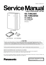
KX-TVM200E

KX-TVM200NE

KX-TVM204X
KX-TVM296NE

(for United Kingdom)
(for Europe)

VOICE PROCESSING SYSTEM

IMPORTANT INFORMATION ABOUT LEAD FREE, (PbF), SOLDERING

If lead free solder was used in the manufacture of this product the printed circuit boards will be marked PbF.
Standard leaded, (Pb), solder can be used as usual on boards without the PbF mark.

When this mark does appear please read and follow the special instructions described in this manual on the use of PbF and how
it might be permissible to use Pb solder during service and repair work.

ORDER NO. KMS0503051CE

Summary of Contents for KX-TVM200E

Page 1: ...N ABOUT LEAD FREE PbF SOLDERING If lead free solder was used in the manufacture of this product the printed circuit boards will be marked PbF Standard leaded Pb solder can be used as usual on boards without the PbF mark When this mark does appear please read and follow the special instructions described in this manual on the use of PbF and how it might be permissible to use Pb solder during servic...

Page 2: ...1 THE RUN LED DOES NOT LIGHT UP OR ABNORMAL WHEN THE POWER SWITCH IS TURNED ON 66 8 2 THE RUN LED DOES NOT BURNS WHEN DPT CONNECTED 67 8 3 TVM204X DSP CARD IS OUT OF ORDER 67 8 4 USB INTERFACE IS OUT OF ORDER 69 8 5 LAN INTERFACE IS OUT OF ORDER 69 8 6 MODEM CARD IS OUT OF ORDER 70 8 7 MAIN CARD IS OUT OF ORDER 70 9 TERMINAL GUIDE OF ICS TRANSISTORS AND DIODES 72 10 HOW TO REPLACE A FLAT PACKAGE I...

Page 3: ... MODEM CARD KX TVM296NE 155 19 2 SPECIFICATIONS OF THE REMOTE MODEM CARD KX TVM296NE 156 19 3 TERMINAL GUIDE OF ICS TRANSISTORS AND DIODES 157 19 4 CABINET AND ELECTRICAL PARTS 158 19 5 ACCESSORIES AND PACKING MATERIALS 159 19 6 REPLACEMENT PARTS LIST KX TVM296NE 160 19 7 FOR THE SCHEMATIC DIAGRAM 161 19 8 SCHEMATIC DIAGRAM KX TVM296NE 162 19 9 PRINTED CIRCUIT BOARD KX TVM296NE 164 3 KX TVM200E KX...

Page 4: ...not to heat too long PbF solder will tend to splash if it is heated much higher than its melting point approximately 1100 F 600 C If you must use Pb solder on a PCB manufactured using PbF solder remove as much of the original PbF solder as possible and be sure that any remaining is melted prior to applying the Pb solder When applying PbF solder to double layered boards please check the component s...

Page 5: ...1 2 HOW TO RECOGNIZE THAT Pb FREE SOLDER IS USED MAIN KX TVM200E KX TVM200NE LED KX TVM200E KX TVM200NE 5 KX TVM200E KX TVM200NE ...

Page 6: ...VM LINK KX TVM200E KX TVM200NE DSP KX TVM204X 6 KX TVM200E KX TVM200NE ...

Page 7: ...DPT KX TVM204X 7 KX TVM200E KX TVM200NE ...

Page 8: ...lectricity When repairing the following precautions will help prevent recurring malfunctions 1 Cover the plastic parts boxes with aluminum foil 2 Ground the soldering irons 3 Use a conductive mat on the worktable 4 Do not touch IC or LSI pins with bare fingers 8 KX TVM200E KX TVM200NE ...

Page 9: ...ed equipment to the customer be sure to perform the following insulation resistance test to prevent the customer from being exposed to shock hazards 3 3 INSULATION RESISTANCE TEST 1 Unplug the power cord and short the two prongs of the plug with a jumper wire 2 Turn on the power switch 3 Measure the resistance value with ohmmeter between the jumpered AC plug and each exposed metal cabinet part suc...

Page 10: ...D HDD is sensitive to shock 3 5 BATTERY CAUTION 1 Danger of explosion if battery is incorrectly replaced Replace only with the same or equivalent type recommended by the manufacturer Dispose of used batteries according to the manufacturer s Instructions 2 The lithium battery is a critical component type No CR23541 Please observe for the proper polarity and the exact location when replacing it and ...

Page 11: ...IS INSERTED INTO ANY 13 AMP SOCKET If a new plug is to be fitted please observe the wiring code as shown below If in any doubt please consult a qualified electrician WARNING THIS APPLIANCE MUST BE EARTHED IMPORTANT The wires in this mains lead are coloured in accordance with the following code Green and Yellow Earth Blue Neutral Brown Live As the colours of the wire in the mains lead of this appli...

Page 12: ...r of Messages Unlimited Length of Personal Greeting Message Up to 360 s programmable Message Retention Time 1 to 30 days unlimited programmable Maximum Message Length 1 to 60 min unlimited programmable Maximum Combined Length of Messages per Mailbox 1 to 600 min unlimited programmable No of Mailbox 1022 Subscriver 2 Manager Reports Mailbox Information Call Account Port Usage Hdd Usage Mailbox Usag...

Page 13: ...e desired party They can dial extension numbers directly or spell the name of the desired party using the dial keys on their telephones When an option has been selected the Automated Attendant responds to the command by either routing the caller to an extension or the operator Once the caller has dialled an appropriate number the VPS transfers the caller to the party 4 2 1 2 Voice Mail Service Voi...

Page 14: ...on of a voice and the control data only with 1 line between the TDA series PBX and the TVM200 that is maximum 24 ports or and the TVM50 that is maximum 6 ports By using VM Link TVM200 can be connected up 24 ports 6 ports in the case of TVM50 without using ports of PBX s line card 4 3 CLIENT APPLICATION 4 3 1 Windows based Administration The Administrator can program and maintain TVM by using windo...

Page 15: ...4 5 SYSTEM CONNECTION DIAGRAM 15 KX TVM200E KX TVM200NE ...

Page 16: ...4 6 NAMES AND LOCATIONS 4 6 1 Outside Inside View 16 KX TVM200E KX TVM200NE ...

Page 17: ...200 supports DPT Integration only therefore it must be connected to the digital extension ports of the PBX Each VPS jack provides 2 VPS ports and can handle 1 call per port Connection Example KX TVM204 x 6 DPT Integration Mode 17 KX TVM200E KX TVM200NE ...

Page 18: ...PTOR 1 Plug the DC connector of the AC adaptor into DC IN 2 Confirm that the VPS power switch is in the OFF position then plug the AC cord into the AC adaptor then plug the other end into an AC outlet 18 KX TVM200E KX TVM200NE ...

Page 19: ...ed to 1 jack of the PBX Use a 4 conductor cable for connection with a Panasonic KX TD series or KX TDA series PBX that uses DPT Integration 4 9 2 Modular Plug Connection Insert the modular plug of each telephone cord into an available modular jack of the VPS 19 KX TVM200E KX TVM200NE ...

Page 20: ...e VPS can be used to program various VPS settings 4 10 1 USB Connection An on site PC can be connected to the VPS via USB 4 10 2 LAN CONNECTION An on site PC can be connected to the VPS over a local area network LAN 20 KX TVM200E KX TVM200NE ...

Page 21: ...he PBX as you would a standard single line telephone SLT Off site programming is possible if trunk calls from the remote PC are routed to the extension port connected to the VPS modem Note that the effective data transfer rate of the internal modem maximum 33 600 bps will be subject to the throughput limitations of the PBX This modem is designed to interwork with the analogue Public Switched Telec...

Page 22: ...4 11 EXPLANATION CONCERNIG MODE SWITCH 22 KX TVM200E KX TVM200NE ...

Page 23: ...4 12 EXPLANTATION CONCERNING LED 23 KX TVM200E KX TVM200NE ...

Page 24: ...24 KX TVM200E KX TVM200NE ...

Page 25: ...t Button Shutdown Button Initiates the shutdown procedure When the Alarm Indicator lights after pressing the ShutdownButton you may safely turn off the power switch Note Make sure the VPS is not in use before pressing the Shutdown Button Mode Switch Used to perform one of several administration service operations by selecting one of 16 positionsthen shutting down and restarting the VPS To change t...

Page 26: ... minutes 2 Turn the power switch off at the VPS 3 Set the Mode Switch 4 Turn the power switch back on at the VPS 5 Connect the station wire s to the VPS and wait approximately 5 min 6 Return the Mode Switch to position 0 USB Port Used to access the VPS via USB VM Link Currently unavailable A VPS PBX connection interface to be implemented in the future via software upgrade 26 KX TVM200E KX TVM200NE...

Page 27: ...ace above the unit for cooling and space on the sides for maintenance and inspection Wiring Precautions Be sure to follow these instructions when wiring Do not wire the telephone cable parallel to an AC power source computer etc If cables are run near those wires shield them with metal tubing or use shielded cables and earth the shields Use protectors if running cables on the floor Avoid running c...

Page 28: ...midity See the graph below Shock Under 5G Vibration 5 Hz to 22Hz 0 0042 cm displacement double amplitude 1 octave per minute 23 Hz 350 Hz Under 0 5G Magnetic Field DC 0 6mT to 700 kHz 0 7µT 700 kHz to 1 5 MHz 3µT Allowable Relative Humidity vs Temperature 28 KX TVM200E KX TVM200NE ...

Page 29: ...rection shown below 1 and slide the cable cover in the direction shown below 2 Turn the cable cover away from the unit and remove it 5 2 HOW TO REMOVE THE FRONT COVER 2 Remove the three screws A 3 While holding both tabs located on the sides of the front cover swing the cover open as shown 29 KX TVM200E KX TVM200NE ...

Page 30: ...ile holding the front cover open at a 45 angle life the cover away from the unit as shown 5 3 HOW TO REMOVE THE HARD DISK DRIVE UNIT AND PCB1 1 Remove the four Screws D 2 Remove the Hard Disk Drive Unit 30 KX TVM200E KX TVM200NE ...

Page 31: ...3 Remove the nine Screws A 4 Remove the one Screws B 5 Remove the PCB1 31 KX TVM200E KX TVM200NE ...

Page 32: ...6 Ch7 8 selector selector DSP 1 2 DSP 3 4 DPT I F DPT I F DPT ECO 11 12 DPT ECO 9 10 3 3v BackUP Ch9 10 Ch11 12 selector selector DSP 1 2 DSP 3 4 DPT I F DPT I F DPT ECO 15 16 DPT ECO 13 14 3 3v BackUP Ch13 14 Ch15 16 selector selector DSP 1 2 DSP 3 4 DPT I F DPT I F DPT ECO 19 20 DPT ECO 17 18 3 3v BackUP Ch17 18 Ch19 20 selector selector DSP 1 2 DSP 3 4 DPT I F DPT I F DPT ECO 23 24 DPT ECO 21 2...

Page 33: ...ernet Frequency 25MHz USB RUNESAS M66591 IC145 USB2 0 Peripheral controller Frequency 24MHz Local Bus Gate Local Bus Gate Gate control IC161 IC109 IC101 IC104 IC169 IC171 IC122 IC123 Gate control of the primary bus only for SDRAMs and the secondary bus only for local devices is performed Slot Interface Circuit Slot Interface Circuit for 4 port Digital Interface Card KX TVA204 TVM204X CN105 CN106 8...

Page 34: ...Bus State Controllers BSC are imbedded for direct connectivity with various memory types In addition the serial communications interface A D converter D A converter timer and real time clock RTC are built in In this system the SH7706 is responsible for the access control of the ROM SDRAM peripheral devices internal RTC bus clock generation and control of other peripheral devices and interfaces usi...

Page 35: ...35 KX TVM200E KX TVM200NE ...

Page 36: ...m operation are loaded into ROM from the HDD on startup 6 1 3 Control Block SDRAM The SDRAM used is 32Mbyte 4M x 16bit 4 banks synchronous DRAM x 1 The SDRAM acts as the work memory of the CPU The SDRAM is controlled by the CPU memory controller The CPU SDRAM bus is synchronous and operates at a bus speed of 65 536MHz 36 KX TVM200E KX TVM200NE ...

Page 37: ...DSP interrupt iVDC Terminal Name and Number Terminal Name Number of Terminals System Terminal 2 SH CPU Interface Terminal Access Control Terminal 47 SH CPU Interface Terminal Interrupt Terminal 4 External Device Control Terminal General purpose Port 6 External Device Control Terminal External Chip Select 3 External Device Control Terminal HDD Interface 2 External Device Control Terminal DSP 30 Ext...

Page 38: ...CO_GATE output L Act ECO data bus enable signal N_ECO_WAIT input L Act ECO wait signal SRAM interface terminal N_MCS2 N_MCS1 output L Act SRAM chip select signal N_MWE output L Act SRAM write enable signal N_MOE output L Act SRAM output read enable signal MA18 MA0 output SRAM address bus MD15 MD0 In out SRAM data bus McBSP0 timing control terminal M02M output 2 048MHz McBSP0 transfer clock M0FS12 ...

Page 39: ...irectly at 32MHz Input frequency is then divided by 2 for 16MHz clocks The reset of the test register is released The test register is usually reset so that values are not writable JTAG terminal TRST input TEST Reset TMS input TEST Mode Select TCK input TEST Clock TDI input TEST Data IN TDO output TEST Data OUT Additional power supply terminal ADD_VDD_0001 ADD_VDD_0012 output Additional VDD 3 3V T...

Page 40: ...40 KX TVM200E KX TVM200NE ...

Page 41: ...uffer for voice data between the DSPs and HDD The voice buffer has memory area for four seconds per channel on both A and B sides giving a total of 24 channels x 4sec A x 4sec B The ASIC iVDC controls the voice buffer through a bus independent from the system bus 41 KX TVM200E KX TVM200NE ...

Page 42: ...nsists of the SMSC s 91C113 Ethernet driver IC and a SpeedTech P52 P14 31A9 connector with a built in transformer This IC driver provides 10 100base T Ethernet integrating MAC and PHY in one chip 42 KX TVM200E KX TVM200NE ...

Page 43: ...In accordance with the USB Universal Serial Bus standard Rev 2 0 the M66591 is a USB peripheral controller that supports both Hi speed and Full speed transfer modes The M6659 has a built in Hi Speed Full Speed transceiver supporting control bulk and interrupt transfers as defined by USB standards 3 5Kbyte FIFO is built in for data transfer which offers up to seven endpoints 43 KX TVM200E KX TVM200...

Page 44: ...44 KX TVM200E KX TVM200NE ...

Page 45: ... of the host in this system the synchronous bus connects directly with the CPU acting as the primary bus and in order to minimize the load capacitance the board is designed taking pattern and run lengths into consideration Other peripheral devices connected to the asynchronous bus are separated by the gate IC and a gate control circuit was added to the board to open the bus as needed 45 KX TVM200E...

Page 46: ...46 KX TVM200E KX TVM200NE ...

Page 47: ...ding receiving voice data the serial bus for DPT signal control various control signals the card power supplies and the identification signal of each card The interface is made up of CN105 and CN106 slot connectors and up to three KX TVA204 TVM204X at maximum can be stacked on each slot connector Up to six KX TVA204 TVM204X 24 ports can be implemented on A and B slots collectively 47 KX TVM200E KX...

Page 48: ...s HDD Interface Circuit is a 40 pin ATA interface for 3 5 HDD ATA mode 4 ready IORDY is supported Multiword DMA transfer is also available Ultra DMA is not supported This system operates in PIO transfer mode 48 KX TVM200E KX TVM200NE ...

Page 49: ...e maintenance the board provides a slot for a modem card Serial send receive signal for sending receiving data with modem IC 3 3v power supply and reset signal capable of separately resetting only the modem are reserved 49 KX TVM200E KX TVM200NE ...

Page 50: ...backup in the event of a momentary power failure The inrush current prevention circuit is provided to ease the inrush current that is generated by the capacitor on startup The DC DC converter also supplies 3 3v to logic components of the main board from the 40v 3 3v is set to start after 40V and 5V are raised to 10v and 4 3v respectively 3 3v mounts the backup circuit with a large capacitance capa...

Page 51: ...witch is turned off In this case a red alarm LED in the front panel lights up by the battery back alarm displaying the state Caution When the jumper J108 is turned on in the power off mode immediately turn on the power to the main board to supply 3 3V to the CPU Once the power of the main board has been turned on the main power supply might be off As stated above turning on J108 in the power off l...

Page 52: ...s The clock master is the ECO ASIC making up the DPT interface The Dch highway on which control data is sent and received by DPT link is usually a path formed between the ECO chip of the channel earliest in order and the HDLC controller embedded in the ASIC By controlling the Dch highway gate this path can be formed between any ECO chip and support is possible even in cases where the ECO of the ch...

Page 53: ...M Link interface signal is first received by the ASIC iVDC and separated into voice data and Dch control data The voice data is transmitted to the voice highway McBSP0 common to all channels and the Dch control data is transmitted to the HDLC controller in the ASIC 53 KX TVM200E KX TVM200NE ...

Page 54: ...tialise Restart Diagnostic Programmer Code Commands Software Version LAN Settings Default Parameters Set Language To select an item from the Utility menu click Utility in the menu bar then select the desired function or utility Certain Utility menu items are also available from the Tool Bar System Back Up Line Status System Trace System Initialise Restart and Commands 54 KX TVM200E KX TVM200NE ...

Page 55: ...ble from the PBX Environment screen This utility allows you to automatically create mailboxes for several extensions at once When you click Next on the PBX Environment screen Auto Configuration dialogue box appears Click OK to start Auto configuration or Cancel to skip Auto Configuration and go to the next setting screen Auto Configuration is available only in Interactive Mode and with Panasonic K...

Page 56: ...iew a record of previous backups a Program System Program DSP Program b System Parameters c System Prompts Installed Prompt Custom Service Menu Company Name Company Greeting System Mailbox Group Voice Label System Caller Name Prompt Selection Hold Announce Menu Extension Group Voice Label d Mailbox Prompts Owner Name Personal Greetings Personal Caller ID Name Interview Personal Group List Name EMD...

Page 57: ...xes or select the mailboxes you wish to backup 9 Click Backup Note The system will prepare the data to be backed up and the backup will begin about 30 seconds later The time needed to backup the data will vary depending on the connection method communication speed and the amount of data that is being backed up Deleted messages will not be backed up by the backup of the Mailbox Messages Restoration...

Page 58: ...up 3 Check the desired data to backup as scheduled 4 Click The Save dialogue box appears 5 Navigate to the folder where to wish to save the system backup file 6 Click OK then click Next 7 Check either All Mailboxes or select the mailboxes you wish to backup then click Next to select mailboxes for Mailbox Messages 8 Check either All Mailboxes or select the mailboxes you wish to backup then click Ne...

Page 59: ...stem prompt 1 Select the desired prompt number 2 Click Delete 3 Click OK To delete the installed language for system prompt 1 Select the desired language Guidance No 2 Click Delete 3 Click OK Record of System Prompt 1 Select the desired System Prompt to record and click Play Record 2 Select Record from extension or Import from recorded file When Record from extension is selected 1 Specify the exte...

Page 60: ...s Each port s status will be displayed as follows Ready The port is ready to be used Incoming Call The port is handling an incoming call Outgoing Call processing sending service DSP Reset processing DSP reset disposition PT Connect processing PT connect disposition Offline Off Line Mode Turning on VPS Call Progression Mode 1 Select the desired port and click Open Line 2 Select Selected Lines to tu...

Page 61: ...ta 1 Click Utility in the menu bar 2 Select System Trace You can click the icon in the tool bar instead of step 1 and 2 Real Time Trace 1 Select Real Time Trace 2 Check Enable Disable Trace Data 3 Check the data and port you wish to monitor 4 Click navigate the folder to save the monitored data as a file 5 Click Apply Note During the Real Time Trace following features cannot be used Other features...

Page 62: ...he VPS 1 Click Utility in the menu bar 2 Select System Initialise Restart Initialise System 1 Select Initialise System You can click the icon in the tool bar instead of step 1 and 2 2 Specify Mailbox No Length 2 5 digits System Manager s Mailbox No and Message Manager s Mailbox No 3 Click Next 4 If there are active ports the System Administrator will be asked to either to continue or to cancel Sel...

Page 63: ...to use KX TVM Maintenance Console Follow the steps below to change the system password 1 Click Utility in the menu bar 2 Select Programmer Code 3 Enter a new password in Enter new password 4 Enter the new password in Confirm new password 5 Click OK 7 10 UTILITY COMMAND The System Administrator can enter commands to maintain the system without closing KX TVM Maintenance Console Follow the steps bel...

Page 64: ...lt Gateway Specifies the IP Address for Default Gateway Port No Specifies the Port No for VPS Value Range 1 65535 7 13 UTILITY DEFAULT PARAMETERS Specifies TVM Type Mailbox No Length System Manager s Mailbox No Message Manager s Mailbox No PBX Type Integration Mode and some parameters as the default settings Follow the steps below for Default Parameters 1 Click Utility in the menu bar 2 Select Def...

Page 65: ...nce Console Note In order to use this feature you need to upgrade the KX TVM Maintenance Console software on a PC connected to the VPS Follow the steps below for Set Language 1 Click Utility in the menu bar 2 Select Set Language 3 Select the language 4 Click OK 65 KX TVM200E KX TVM200NE ...

Page 66: ...8 TROUBLESHOOTING GUIDE 8 1 THE RUN LED DOES NOT LIGHT UP OR ABNORMAL WHEN THE POWER SWITCH IS TURNED ON 66 KX TVM200E KX TVM200NE ...

Page 67: ...8 2 THE RUN LED DOES NOT BURNS WHEN DPT CONNECTED 8 3 TVM204X DSP CARD IS OUT OF ORDER 67 KX TVM200E KX TVM200NE ...

Page 68: ...68 KX TVM200E KX TVM200NE ...

Page 69: ...OF ORDER Please confirm the USB cable and the USB driver software when you can not connect USB 8 5 LAN INTERFACE IS OUT OF ORDER Please confirm LAN cable HUB and IP address when you can not connect LAN 69 KX TVM200E KX TVM200NE ...

Page 70: ...8 6 MODEM CARD IS OUT OF ORDER 8 7 MAIN CARD IS OUT OF ORDER 70 KX TVM200E KX TVM200NE ...

Page 71: ...71 KX TVM200E KX TVM200NE ...

Page 72: ...9 TERMINAL GUIDE OF ICS TRANSISTORS AND DIODES 72 KX TVM200E KX TVM200NE ...

Page 73: ...ith some tools like a soldering wire If some solder is left at the joint on the board the new IC will not be attached properly 10 3 INSTALLATION PROCEDURE 1 Tack the flat pack IC to the PCB by temporarily soldering two diagonally opposite pins in the correct positions on the PCB Be certain each pin is located over the correct pad on the PCB 2 Apply flux to all of the pins on the IC 3 Being careful...

Page 74: ...11 FIXTURES AND TOOLS 74 KX TVM200E KX TVM200NE ...

Page 75: ...12 CABINET AND ELECTRICAL PARTS LOCATION 75 KX TVM200E KX TVM200NE ...

Page 76: ...13 ACCESSORIES AND PACKING MATERIAL 76 KX TVM200E KX TVM200NE ...

Page 77: ...PSKE1056Z1 GUIDE PC ABS UL94 5V 12 PSKE1062Z1 COVER PC ABS UL94 5V 13 PSKE1077Z1 COVER PC ABS UL94 5V 14 PSKM1107U1 CABINET BODY PC ABS UL94 5V 15 PSKV1031Z1 COVER PC ABS UL94 5V 16 PSMC1120Z SHIELD PARTS FERRITE SHEET 17 PSMH1286Z ANGLE 18 PSMH1287Z ANGLE 19 PSQT1982Z LABEL WARNING 20 PSQT1983Z LABEL CAUTION 21 PSUS1025Z COIL SPRING LOCK 22 PSWSTVM200NE SWITCH ASS Y 23 PSWETVM200E HARD DISK DRIVE...

Page 78: ...000006 DIODE SI D114 MA8100M DIODE SI S D115 B0JCPG000010 DIODE SI D116 B0JCPG000010 DIODE SI D118 MA1070400L DIODE SI S D119 MA728 DIODE SI S D120 MA728 DIODE SI S D123 B0JCND000008 DIODE SI D125 B0JCND000008 DIODE SI D126 B0JCPC000006 DIODE SI D127 B0JCNG000006 DIODE SI D129 MA8043M DIODE SI S IC147 B0KB00000036 DIODE SI BATTERY BAT101 CR23541GUF LITHIUM BATTERY CONNECTORS CN101 PSJP03A93Z CONNE...

Page 79: ...RRAY 33 RA210 D1H83304A024 RESISTOR ARRAY 33 RA211 D1H83304A024 RESISTOR ARRAY 33 RA212 D1H83304A024 RESISTOR ARRAY 33 RA213 D1H81034A024 RESISTOR ARRAY 10K RA214 D1H81034A024 RESISTOR ARRAY 10K RA215 D1H81034A024 RESISTOR ARRAY 10K RA216 D1H81034A024 RESISTOR ARRAY 10K RA217 D1H83304A024 RESISTOR ARRAY 33 RA218 D1H83304A024 RESISTOR ARRAY 33 RA219 D1H83304A024 RESISTOR ARRAY 33 Ref No Part No Par...

Page 80: ...20 ECUE1C103KBQ 0 01 S C21 ECUE1C103KBQ 0 01 S C22 ECUE1C103KBQ 0 01 S C23 ECUE1C103KBQ 0 01 S C24 ECUE1C103KBQ 0 01 S C25 ECUE1C103KBQ 0 01 S C26 ECUE1C103KBQ 0 01 S C27 ECUE1C103KBQ 0 01 S Ref No Part No Part Name Description Remarks C29 ECUE1C103KBQ 0 01 S C30 ECUE1C103KBQ 0 01 S C32 ECUE1C103KBQ 0 01 S C33 ECUE1C103KBQ 0 01 S C34 ECUE1C103KBQ 0 01 S C51 ECUE1C103KBQ 0 01 S C52 ECUE1C103KBQ 0 0...

Page 81: ... C260 ECUV1H103KBV 0 01 S C261 ECUV1A105ZFV 1 C262 PQCUV1A225ZF 2 2 S C263 ECUV1H103KBV 0 01 S C265 ECUV1A105ZFV 1 Ref No Part No Part Name Description Remarks C266 PQCUV1A225ZF 2 2 S C267 EEEHB1A221P 220 C270 EEEHB1A221P 220 C273 ECUV1H103KBV 0 01 S C275 ECUV1A105ZFV 1 C277 PQCUV1A225ZF 2 2 S C279 EEEHB1A221P 220 C282 ECUV1H180JCV 18P C283 ECUV1H180JCV 18P C284 ECUV1C104ZFV 0 1 C285 ECUV1A105ZFV ...

Page 82: ...2 ECUE1H221JCQ 220P S C423 ECUE1C103KBQ 0 01 S C424 ECUE1C103KBQ 0 01 S C425 ECUE1C103KBQ 0 01 S Ref No Part No Part Name Description Remarks C426 ECUE1H221JCQ 220P S C427 ECUE1C103KBQ 0 01 S C428 ECUE1C103KBQ 0 01 S C429 ECUE1C103KBQ 0 01 S C430 ECUE1H221JCQ 220P S C431 ECUE1C103KBQ 0 01 S C432 ECUE1C103KBQ 0 01 S C433 ECUE1C103KBQ 0 01 S C434 ECUE1H221JCQ 220P S C435 ECUE1C103KBQ 0 01 S C436 ECU...

Page 83: ...03KBQ 0 01 S C642 ECUE1C103KBQ 0 01 S C643 ECUE1C103KBQ 0 01 S C644 ECUE1C103KBQ 0 01 S C645 ECUE1C103KBQ 0 01 S C646 ECUE1C103KBQ 0 01 S C647 ECUE1C103KBQ 0 01 S C648 ECUE1C103KBQ 0 01 S C649 ECUE1C103KBQ 0 01 S C650 ECUE1C103KBQ 0 01 S Ref No Part No Part Name Description Remarks C651 ECUE1C103KBQ 0 01 S C652 ECUE1C103KBQ 0 01 S C653 ECUE1C103KBQ 0 01 S C654 ECUV1E104ZFV 0 1 C655 ECUV1C104ZFV 0 ...

Page 84: ... R143 ERJ3GEY0R00 0 R144 ERJ3GEY0R00 0 R145 ERJ3GEY0R00 0 R146 ERJ3GEYJ330 33 R147 ERJ3GEYJ330 33 Ref No Part No Part Name Description Remarks R148 ERJ3GEYJ330 33 R149 ERJ3GEYJ330 33 R150 ERJ3GEYJ330 33 R151 ERJ3GEYJ330 33 R152 ERJ3GEYJ330 33 R153 ERJ3GEY0R00 0 R154 ERJ3GEY0R00 0 R155 ERJ3GEYJ330 33 R156 ERJ3GEYJ100 10 R157 ERJ3GEYJ101 100 R158 ERJ3GEY0R00 0 R159 ERJ3GEY0R00 0 R160 ERJ3GEY0R00 0 R...

Page 85: ...R429 ERJ3GEYJ221 220 R430 ERJ3GEYJ221 220 R431 ERJ3GEY0R00 0 R433 ERJ3GEY0R00 0 R435 ERJ3GEY0R00 0 Ref No Part No Part Name Description Remarks R437 ERJ3GEYJ330 33 R438 ERJ3GEYJ330 33 R439 ERJ3GEYJ330 33 R440 ERJ3GEYJ330 33 R441 ERJ3GEY0R00 0 R443 ERJ3GEY0R00 0 R445 ERJ3GEY0R00 0 R447 ERJ3GEY0R00 0 R449 ERJ3GEY0R00 0 R451 ERJ3GEYJ330 33 R487 ERJ3GEY0R00 0 R489 ERJ3GEY0R00 0 R492 ERJ3GEY0R00 0 R529...

Page 86: ...3 R679 ERJ3GEYJ152 1 5K R680 ERJ3GEYJ122 1 2K R684 ERJ3GEY0R00 0 Ref No Part No Part Name Description Remarks R687 ERJ3GEY0R00 0 R690 ERJ3GEY0R00 0 R691 ERJ3GEYJ151 150 R692 ERJ3GEY0R00 0 R694 ERJ3GEY0R00 0 R695 ERJ3GEY0R00 0 R696 ERJ3GEYJ151 150 R702 ERJ3GEY0R00 0 R703 ERJ3GEY0R00 0 R730 D0GB223ZA002 22K R731 ERJ3GEYF272 2 7K S R732 ERJ3GEYF474 470K S R733 ERJ3GEYF473 47K S R734 ERJ3GEYJ225 2 2M ...

Page 87: ...931 ERJ3GEYJ470 47 R932 ERJ3GEYJ470 47 R933 ERJ3GEYJ470 47 R934 ERJ3GEYJ470 47 R935 ERJ3GEYJ470 47 Ref No Part No Part Name Description Remarks R936 ERJ3GEYJ470 47 R937 ERJ3GEYJ470 47 R938 ERJ3GEYJ470 47 R939 ERJ3GEYJ470 47 R940 ERJ3GEYJ101 100 R941 ERJ3GEYJ101 100 R942 ERJ3GEYJ101 100 R943 ERJ3GEYJ101 100 R944 ERJ3GEYJ101 100 R945 ERJ3GEYJ101 100 R946 ERJ3GEYJ101 100 R947 ERJ3GEYJ101 100 R948 ERJ...

Page 88: ...V 0 01 S C904 ECUV1H103KBV 0 01 S C905 ECUV1H103KBV 0 01 S Ref No Part No Part Name Description Remarks RESISTORS L900 PQ4R10XJ000 0 S L909 PQ4R10XJ000 0 S L910 PQ4R10XJ000 0 S R902 ERJ3GEY0R00 0 R903 ERJ3GEYJ223 22K R904 ERJ3GEYJ330 33 R905 ERJ3GEYJ221 220 R906 ERJ3GEYJ221 220 R907 ERJ3GEYJ181 180 R908 ERJ3GEYJ220 22 R909 ERJ3GEYJ220 22 R910 ERJ3GEYJ181 180 R911 ERJ3GEYJ221 220 R912 ERJ3GEYJ221 2...

Page 89: ... 9 10 3 3v BackUP Ch9 10 Ch11 12 selector selector DSP 1 2 DSP 3 4 DPT I F DPT I F DPT ECO 15 16 DPT ECO 13 14 3 3v BackUP Ch13 14 Ch15 16 selector selector DSP 1 2 DSP 3 4 DPT I F DPT I F DPT ECO 19 20 DPT ECO 17 18 3 3v BackUP Ch17 18 Ch19 20 selector selector DSP 1 2 DSP 3 4 DPT I F DPT I F DPT ECO 23 24 DPT ECO 21 22 3 3v 3 3v BackUP Ch21 22 Ch23 24 selector selector RS 422 Driver recever LAN ...

Page 90: ...90 KX TVM200E KX TVM200NE ...

Page 91: ...91 KX TVM200E KX TVM200NE ...

Page 92: ...92 KX TVM200E KX TVM200NE ...

Page 93: ...93 KX TVM200E KX TVM200NE ...

Page 94: ...EQ 104 WAIT 124 CAP1 127 CAP2 131 XTAL 132 EXTAL 138 CKI0 147 CTS2 IRQ5 SCPT 5 149 RESETM 151 IRQ0 IRL0 PTH 0 152 IRQ1 IRL1 PTH 1 153 IRQ2 IRL2 PTH 2 154 IRQ3 IRL3 PTH 3 155 IRQ4 PTH 4 160 DREQ0 PTH 5 161 DREQ1 PTH 6 165 RESETP FIL106 1 2 3 IC128 1 2 4 3 5 TP834 TP108 n_HDB_gate NC R811 RA122 33 1 2 3 4 5 6 7 8 RA119 10k 1 2 3 4 5 6 7 8 RA115 10k 1 2 3 4 5 6 7 8 RA206 22 1 2 3 4 5 6 7 8 RA208 22 1...

Page 95: ...TP942 IC169 4 5 6 IC169 1 2 3 TP1178 SW102 IC169 14 7 3 3V DG 0 01u C603 3 3V 0 01u C607 DG IC169 12 13 11 NC R809 0 R810 DG IC171 4 5 6 TP1186 IC171 9 10 8 0 01u C611 3 3V DG IC171 14 7 IC171 12 13 11 DG TP1190 IC169 10 9 8 DG 3 3V RA102 10k 4 3 2 1 8 7 6 5 RA111 10k 1 2 3 4 5 6 7 8 RA171 10k 1 2 3 4 5 6 7 8 10k RA172 1 2 3 4 5 6 7 8 RA112 10k 1 2 3 4 5 6 7 8 10k RA170 1 2 3 4 5 6 7 8 RA106 10k 4...

Page 96: ...7 N_ECO_CS 2 8 N_ECO_CS 3 9 N_ECO_CS 4 23 N_DSP_HINT 1 24 N_DSP_HINT 2 25 N_DSP_HINT 3 26 N_DSP_HINT 4 27 N_DSP_HINT 5 28 N_DSP_HINT 6 29 N_DSP_HINT 7 30 N_DSP_HINT 8 31 N_DSP_HINT 9 33 N_DSP_HINT 10 34 N_DSP_HINT 11 35 N_DSP_HINT 12 37 DSP_HRDY 38 HBIL 39 HCNTL 0 40 HCNTL 1 41 N_DSP_DS 1 42 N_DSP_DS 2 43 N_DSP_DS 3 44 N_DSP_DS 4 45 N_DSP_DS 5 48 N_DSP_DS 6 49 N_DSP_DS 7 50 N_DSP_DS 8 51 N_DSP_DS ...

Page 97: ...1 C4 0 01 C85 0 1 C30 0 01 C89 0 1 C90 0 1 C86 0 1 DG 1 9VB 7 8 11 10 9 1 OEP0 2 OSX 5 VSS1 6 VDD1 10 N_ECO_CS 5 11 N_ECO_CS 6 12 N_ECO_CS 7 13 N_ECO_CS 8 14 N_ECO_CS 9 15 N_ECO_CS 10 16 N_ECO_CS 11 17 N_ECO_CS 12 18 VSS2 19 VDD2 20 N_ECO_RE 21 N_ECO_WE 22 N_ECO_GATE 32 VSS3 36 ADD_VDD_0001 46 VSS4 47 VDD3 57 N_IDCS0 58 N_IDCS1 59 VSS5 60 VDD4 61 DPT_CLK 63 TRST 64 TDI 65 TCK 66 TMS 67 TDO 70 O_DP...

Page 98: ... 4 5 6 7 8 RA192 33 1 2 3 4 5 6 7 8 RA193 33 1 2 3 4 5 6 7 8 RA200 82 4 3 2 1 8 7 6 5 RA201 82 4 3 2 1 8 7 6 5 RA216 10k 4 3 1 2 7 8 6 5 RA215 10k 4 3 2 1 8 7 6 5 3 3V RA213 10k 1 2 3 4 5 6 7 8 RA214 10k 4 3 1 2 7 8 6 5 3 3V RA217 33 1 2 3 4 5 6 7 8 22 RA223 4 3 2 1 8 7 6 5 22 RA222 4 3 2 1 8 7 6 5 D C B A 4 6 3 5 2 1 IC122 1 DIR 2 A1 3 A2 4 A3 5 A4 6 A5 7 A6 8 A7 9 A8 10 GND 11 B8 12 B7 13 B6 14 ...

Page 99: ...LA 4 RA151 10k 1 2 3 4 5 6 7 8 DG 33 R791 5VH 5VH 5VH 5VH 5VH TP1134 TP1135 TP1136 TP1137 TP1138 TP1139 TP1140 TP1141 TP1142 TP951 n_HDB_gate TP1182 TP637 RA202 82 4 3 2 1 8 7 6 5 RA203 82 4 3 2 1 8 7 6 5 RA204 82 1 2 3 4 5 6 7 8 R813 10K 3 3V 22 RA225 4 3 2 1 8 7 6 5 22 RA224 4 3 2 1 8 7 6 5 DG 4 7K R909 4 7K R910 4 7K R911 4 7K R912 IC166 5 6 F E H G 4 6 3 5 2 1 CN104 1 2 3 4 5 6 7 8 9 10 11 12 ...

Page 100: ...R540 22 R543 22 R544 FIL143 1 2 3 FIL145 1 2 3 FIL146 1 2 3 FIL148 1 2 3 FIL144 1 2 3 DG FIL147 1 2 3 FIL141 1 2 3 FIL142 1 2 3 TP1028 FIL155 1 2 3 22 R995 DG LD 0 7 n_DSPINT78 n_DSPINT1314 n_DSPINT2122 n_DSPINT2324 n_DSPINT1516 n_DSPINT56 LDc 2 MBFS1_78 LDc 1 MBCLK1 LDc 0 MBFS1_2122 MBDR1 MBFS1_1314 MBFS1_56 MBFS1_1516 MBDX1 MBFS1_2324 MBDR1 MBDX1 MBFS1_910 MBFS1_1718 MBFS1_34 MBFS1_1112 MBFS1_19...

Page 101: ...L0c n_ECOCS12 n_ECOCS910 n_DSPINT34 n_GCH1 4 HBILc n_DSPCS1718 n_ECOCS1718 n_DSPRST12 n_DSPCS12 n_DSPCS1112 n_DSPINT1718 CPC1 n_DSPRST1112 Hook1 n_DSPRST1718 CPC2 n_ECOREc HCNTL1c n_ECOCS34 n_DSPRST910 BELL2 n_DSPINT1920 BELL1 n_ECO_WAIT17 20 n_DSPRST1920 Hook2 n_ECOCS1920 n_DSPCS910 n_ECO_WAIT1 4 DSP_RWc n_DSP_RDY1 4 n_DSPINT1112 n_ECOCS1112 n_DSPRST34 n_DSPCS34 n_DSPCS1920 RD_nWRGc n_SLOT_GATE n...

Page 102: ... 0 15 USB_DACK CN107 1 2 3 4 5 6 7 8 9 10 11 12 13 14 15 16 17 18 19 20 21 22 23 24 33 R594 33 R595 33 R593 SHW_DHW1 SHW_FH SHW_CLK SHW_UHW1 33 R596 DG C275 1 0u C277 2 2u C273 0 01u DG C279 10V220m 3 3V IC165 1 2 3 IC165 4 5 6 DG SHWDHW1 SHWFH SHWCLK SHWUHW1 0 1u C581 DG TP1159 TP1160 TP1161 TP1154 TP1155 TP1156 TP1157 TP1158 FIL137 1 2 3 IC166 9 8 TP1321 n_LAN_CS n_USB_CS n_USB_RST2 n_LAN_WAIT V...

Page 103: ... 3V 3 3V_USB 3 3V_LAN C281 NC n_AUDATA1 BELL5 n_AUDATA0 CPC6 n_AUDSYNC Hook6 n_AUDATA3 Hook5 n_AUDATA2 BELL6 33 R588 33 R589 33 R590 33 R591 33 R592 TCK TDO_A ASEBRKAK TDI n_RESET TMS n_ASEMDO n_TRST 33 R597 33 R598 33 R599 33 R601 33 R602 33 R603 33 R604 33 R605 TDO_B 33 R600 IC166 3 4 DG IC165 14 7 0 01u C567 3 3V IC165 13 12 11 DG nAUDD0 nAUDD1 nAUDD2 nAUDD3 nAUDSYNC TCK TMS nTRST TDI TDO ASEBR...

Page 104: ...W C331 10p C338 0 01u C336 1 0u C306 0 01u C341 0 01u C307 0 01u C337 0 01u C310 0 01u C332 0 1u C325 0 01u C342 10p C319 0 1u C333 0 1u C318 0 01u C328 0 01u C330 10p C321 0 01u C343 0 1u C316 10p C339 0 01u C315 0 01u C340 0 01u TP705 TP672 TP738 TP739 TP740 TP741 TP742 TP743 TP744 TP745 TP746 TP747 TP748 TP749 TP750 TP751 TP717 TP716 TP667 TP664 TP663 TP702 TP703 TP704 TP708 TP707 TP711 TP712 T...

Page 105: ...u C301 1u C300 0 1u C298 0 1u C299 1u C317 1u C308 0 1u C311 1u C305 1u 1u C578 0 1u C579 1 VDD1 2 nCSOUT 3 IOS0 4 IOS1 5 IOS2 6 ENEEP 7 EEDO 8 EEDI 9 EESK 10 EECS 11 AVDD11 12 RBIAS 13 AGND13 16 AVDD16 19 AGND19 21 LBK 22 nLEDA 23 nLEDB 24 GND24 25 MDI 26 MDO 27 MCLK 29 INTR0 30 RESET 31 nRD 32 nWR 33 VDD33 34 NC34 35 nCYCLE 36 W nR 37 nADS 38 ARDY 39 GND39 40 nVLBUS 41 AEN 42 LCLK 43 nSRDY 44 VD...

Page 106: ...TP888 TP882 TP886 D108 5 1V D112 1 2 3 TP880 TP884 TP878 RA168 10K 4 3 2 1 8 7 6 5 D109 7 5V 100K R747 R745 330K MOS102 60V5A or more S D G R744 47K R746 33K D111 U102 1 6 2 L203 TP875 TP1166 TP1165 IC151 VIN 1 2 OUTPUT 3 GND 4 FEEBACK 5 nON OFF 0 1u C550 0 1u C551 D C B A 4 6 3 5 2 1 U103 1 6 2 U103 4 3 5 Q116 E C B U101 1 6 2 NC R959 TP1354 NC R956 TP1355 NC R957 DG NC U106 4 3 5 DG NC U106 1 6 ...

Page 107: ...0 01u C411 0 01u L202 C362 220P C412 220P C366 220P C409 220P C442 220P C418 220P C377 220P C415 220P C426 220P C430 220P C381 220P C401 220P C438 220P DG C422 220P C405 220P C369 220P 3 3V C358 220P C354 220P C385 220P C397 220P C373 220P C434 220P C393 220P C446 220P C389 220P C522 220P C526 220P C518 220P 3 3V C353 0 01u DG C357 0 01u C365 0 01u C361 0 01u C378 0 01u C382 0 01u C374 0 01u C370 ...

Page 108: ...J110 DG P G 12VH 3 3VC 3 3VC 5VH TP1174 TP1175 TP1173 220u 25V C591 DG P G DG P G DG P G DG P G 390F R789 100uH 1 1A L214 1K F R786 2 7KF R788 5VH nDC_ALM TP1168 TP1172 C207 0 1u C206 0 1u 4700P J C590 1000P J C560 IC167 VIN 1 2 OUTPUT 3 GND 4 FEEBACK 5 nON OFF D126 20V3A 3 2 1 C53 0 01 C54 0 01 D C B A 7 8 11 10 9 1W 10 R917 TP1314 U107 4 3 5 56K R963 U107 1 6 2 MOS103 S D G 5 6K R964 68K R965 10...

Page 109: ...E G TP912 C62 0 01 1 9V C29 0 01 3 3V DG 3 3V C565 1 0u R769 1 DG C60 0 01 C61 0 01 150k R784 150k R785 3 3F 2 5V C589 3 3F 2 5V C588 DG D125 TP904 DG 3 3VN 0 R962 NC R961 Vz 4 3V D129 TP1356 TP1357 TP1362 39K R970 10K R969 1W 3 9 R787 DG DG TP1363 TP1364 18K R967 U108 1 6 2 U108 4 3 5 1 8K R968 12VH 12VH Q117 E C B IC174 1 GND 2 VDD 3 VOUT 4 EXT 5 CE R979 10K R980 680 DG C617 10u DG TP1368 TP1369...

Page 110: ...3 D0 4 EN1 2 5 D02 6 D02 7 DI2 9 DI3 10 D03 11 D03 12 EN3 4 13 D04 14 D04 15 DI4 IC901 1 RI1 2 RI1 3 RO1 4 EN1 2 5 RO2 6 RI2 7 RI2 9 RI3 10 RI3 11 RO3 12 EN3 4 13RO4 14 RI4 15 RI4 CN900 1 2 3 4 5 6 7 8 9 10 11 12 13 14 15 16 17 18 19 20 21 22 23 24 3 3V DG DG 0 1 C902 0 L900 NC R900 FIL900 1 2 3 3 3V 2 2 C900 DG TP1 1 0 C901 TP2 IC900 16 8 0 01u C903 0 01u C904 IC901 16 8 0 R902 NC R901 DG 3 3VF L...

Page 111: ...7 FIL903 1 2 4 3 NC R925 NC R923 FIL901 1 2 4 3 NC R920 NC R924 FIL902 1 2 4 3 NC R921 NC R922 SHWCLK LDHW1 SHWFH LUHW1 SHWFH SHWCLK LDHW1 LUHW1 CN901 1 2 3 4 5 6 7 8 9 10 11 12 FG 0 L909 DG 0 L910 D900 1 1 GND 2 3 3 4 4 VBUS 5 6 6 DG 3 3VF 3 3VF DG D901 1 1 GND 2 3 3 4 4 VBUS 5 6 6 GND LUHW SHWCLK Frame SHWFH LDHW LDHW GND SHWCLK Frame LUHW SHWFH 1 2 3 4 5 6 7 8 KX TVM200E KX TVM200NE VM LINK 111...

Page 112: ...356 2 1 C355 R909 C212 C209 R348 R349 R350 R351 R791 C654 R216 R217 C441 C86 C90 C175 C178 RA101 RA102 RA103 RA104 R889 C133 C134 R123 C202 R792 R703 C132 C571 FIL112 RA105 RA122 RA121 RA120 RA106 RA107 RA108 C570 C569 FIL105 C91 C645 R343 R344 R235 R238 R245 R295 R294 1 5 5 4 MOS104 8 1 6 4 3 1 D126 1 5 RA165 C333 L217 C335 C19 C20 RA164 C18 C344 J104 C17 IC148 L115 J102 R690 R646 R643 L196 C16 I...

Page 113: ...C644 C88 R796 C194 C446 R806 L215 RA144 RA146 RA147 RA142 C610 C609 RA139 FIL188 RA141 C191 C187 FIL115 R795 L179 C92 C5 C89 C643 C176 C642 L151 C181 C81 R286 R240 R288 R895 R896 R893 C173 R892 R239 RA177 RA176 RA181 RA180 RA175 RA174 R335 C525 RA173 R801 RA143 RA145 RA140 R797 C608 C394 R803 R802 R805 R804 C526 R799 R798 R800 RA182 RA179 RA178 R141 R244 C638 C639 C392 C172 C87 R313 R328 R248 R314...

Page 114: ...901 C900 C903 R923 R924 R915 R916 R917 R918 R919 FIL903 R925 R900 IC900 IC901 C904 CN900 D900 R905 R912 R921 R922 FIL901 FIL902 R927 R920 R926 FIL904 RA900 RA901 C905 R908 R909 R910 R914 L901 R913 R907 R911 R906 L907 L908 R901 R902 R904 Q900 R903 D901 PSUP1482Z KX TVM200E KX TVM200NE VM BOAD PbF A CN901 9 4 2 1 5 6 7 10 16 9 8 1 2 24 16 9 8 1 23 1 114 KX TVM200E KX TVM200NE ...

Page 115: ...18 KX TVM204X 4 PORT DIGITAL EXPANSION CARD 115 KX TVM200E KX TVM200NE ...

Page 116: ...tems Extension Bolt x 3 Screw x 3 Installation 1 Position the card so that the jacks fit in the open slot Make sure that the tabs on both sides of the card fit into place Holding the card firmly in place lower the other end of the card so that the card s hole fits over the extension bolt CAUTION When installing optional cards do not put pressure on the main board Doing so may result in damage to t...

Page 117: ...Cards in Slot 5 or Slot 6 When installing a card in Slot 5 or 6 secure the cars using the screws included with the card instead of the extension bolts Note The KX TVM204 operates at SELV 117 KX TVM200E KX TVM200NE ...

Page 118: ...ompress and decompress voice data of voice mail units generates and receives DTMF tones detects AGC VOX and CPT and controls the volume and playback speeds etc The number of installed channels is two per DSP Up to 12 DSPs 24 channels at the maximum are controlled by the host CPU and iVDC ASIC DSP Function DSP TI TMS320VC5409 80 Clock MIPS External Input 8 000MHz Processing Speed 80MIPS Operating V...

Page 119: ...119 KX TVM200E KX TVM200NE ...

Page 120: ...clock slave see the references at the end of the chapter McBSP1 sends and receives the data compressed between the ASIC and the DSP and the data decompressed by the DSP The DSP is a clock slave and the clock master is the ASIC McBSP1 forms the serial communication that sends and receives 16 bit command data and 16 bit data on the base clock 8 MHz respectively with 24 channels x 2 mainframe subfram...

Page 121: ...e PBX interface and the DSP As for the data to be handled only 2 channel 8 bit MSB First voice data are sent and received The frame pulse remains active during valid data are asserted according to the specifications of the PBX interface ASIC There is no data delay in frame pulses and data sent and received 121 KX TVM200E KX TVM200NE ...

Page 122: ...ommand data 16 bits and voice data 16 bits are arranged as mainframe and subframe and 48 frames of 24 channels are timeshared and arranged on this serial communication format Each DSP sends and receives commands and data of two channels of serial communication signals As DFH 1 12 signals that show the dedicated data frame heads are input into each DSP each DSP sends and receives data to and from t...

Page 123: ...of Power ON normal DX High Err and at the time of Power DOWN DX Low The remaining pin FSX must be kept capable as input of reading the status from CPU HPI 8 The HPI 8 is controlled directly by the CPU and performs command settings from the CPU to the DSP FIFO style command sending and receiving such as DSP status reads and DSP program downloads on system startups or software updates Program downlo...

Page 124: ...ignated register after which DSPINT is asserted to the HPIC register sending an interrupt to the DSP In concordance with this interrupt the DSP performs appropriate task processing such as reading designated registers Reset The DSP reset signal has individual reset signal capability and performs system reset at POWER ON in addition to resets to each DSP chip independently Memory map In addition to...

Page 125: ...125 KX TVM200E KX TVM200NE ...

Page 126: ...Reference 1 126 KX TVM200E KX TVM200NE ...

Page 127: ...Reference 2 127 KX TVM200E KX TVM200NE ...

Page 128: ... 3 ECO This ASIC dedicated to DPT interface communication is the PCC digital PBX extension interface PBX Interface Related output input signal PDR PDR0 PDR1 1 PVRH PVRL PDX0 PDX1 128 KX TVM200E KX TVM200NE ...

Page 129: ...t time is 512KHz 1 95µs and the information encoding used is AMI Table 3 1 Information Field Explanation Field name Bit number Explanation SYNC 5 Continuous 00000 pattern used for clock extraction by PLL MAM 3 A 000 pattern 01 01 10 violating the AMI encoding side used to detect the header of the received frame C 1 Valid data inverted from B1 channel 2 D 2 Valid data inverted from B2 channel B1 8 ...

Page 130: ...130 KX TVM200E KX TVM200NE ...

Page 131: ...131 KX TVM200E KX TVM200NE ...

Page 132: ...18 4 TERMINAL GUIDE OF ICS TRANSISTORS AND DIODES 132 KX TVM200E KX TVM200NE ...

Page 133: ...18 5 CABINET AND ELECTRICAL PARTS 133 KX TVM200E KX TVM200NE ...

Page 134: ...18 6 ACCESSORIES AND PACKING MATERIALS 134 KX TVM200E KX TVM200NE ...

Page 135: ...539 IC IC802 C0JBAZ001466 IC IC803 C0JBAZ001466 IC IC804 C0JBAZ001466 IC IC805 C0JBAZ001466 IC IC806 C0JBAZ001466 IC IC807 C0JBAZ001466 IC IC808 C0JBAZ001466 IC IC809 C0JBAZ001466 IC IC810 C0JBAZ001466 IC IC811 C2HBBF000005 IC IC813 PSVITC7WU04F IC IC817 C2HBBF000005 IC IC819 C0JBAB000407 IC IC823 C0JBAZ001466 IC IC825 C0JBAA000244 IC IC829 C0JBAA000244 IC IC830 C0JBAA000244 IC IC836 C0JBAE000231 ...

Page 136: ...KBV 0 01 S C844 PQCUV1A225ZF 2 2 S C845 ECUV1C104ZFV 0 1 C846 PQCUV1A225ZF 2 2 S C847 ECUV1A105ZFV 1 C848 ECUV1C104ZFV 0 1 C849 ECUV1A105ZFV 1 Ref No Part No Part Name Description Remarks C850 ECUV1C104ZFV 0 1 C851 ECUV1C104ZFV 0 1 C852 ECUV1C104ZFV 0 1 C853 ECUV1H103KBV 0 01 S C854 ECUV1H103KBV 0 01 S C855 ECUV1H103KBV 0 01 S C856 ECUV1C104ZFV 0 1 C857 ECUV1C104ZFV 0 1 C858 ECUV1C104ZFV 0 1 C859 ...

Page 137: ... 56 R875 ERJ3GEYJ221 220 R876 ERJ3GEYJ220 22 R877 ERJ3GEYJ221 220 R879 ERJ3GEYJ221 220 Ref No Part No Part Name Description Remarks R881 ERJ3GEYJ472 4 7K R882 ERJ3GEYJ103 10K R883 ERJ3GEYJ103 10K R884 ERJ3GEYJ560 56 R886 ERJ3GEY0R00 0 R887 ERJ3GEYJ105 1M R888 ERJ3GEY0R00 0 R889 ERJ3GEY0R00 0 R890 ERJ3GEYJ220 22 R891 ERJ3GEYJ103 10K R892 ERJ3GEYJ103 10K R893 ERJ3GEYJ103 10K R894 ERJ3GEYJ103 10K R89...

Page 138: ...B TRANSFORMER T701B ETJS13ZA14AB TRANSFORMER VARISTORS ZNR71A ERZC07DK820 VARISTOR S Ref No Part No Part Name Description Remarks ZNR71B ERZC07DK820 VARISTOR S ZNR72A ERZC07DK820 VARISTOR S ZNR72B ERZC07DK820 VARISTOR S CAPACITORS C701 ECUV1H100DCV 10P S C702 ECUV1H100DCV 10P S C703 EEEHB1A101P 100 C704 ECUV1H103KBV 0 01 S C705 ECUV1A105ZFV 1 C706A ECUV1E104ZFV 0 1 C706B ECUV1E104ZFV 0 1 C707A ECU...

Page 139: ...R747A D1EN391J0001 390 R747B D1EN391J0001 390 R748A D1EN391J0001 390 R748B D1EN391J0001 390 R750A ERJ3GEYJ100 10 R750B ERJ3GEYJ100 10 R751A ERJ3GEYJ100 10 R751B ERJ3GEYJ100 10 R752A ERJ3GEYJ100 10 R752B ERJ3GEYJ100 10 R753A ERJ3GEYJ100 10 R753B ERJ3GEYJ100 10 R754A ERJ3GEYJ100 10 Ref No Part No Part Name Description Remarks R754B ERJ3GEYJ100 10 R755A ERJ3GEYJ100 10 R755B ERJ3GEYJ100 10 R756A ERJ3G...

Page 140: ...18 8 MEMO 140 KX TVM200E KX TVM200NE ...

Page 141: ...RAM Note 1 DC voltage measurements are taken with an oscilloscope or a tester with a ground 2 The schematic diagrams and circuit board may be modified at any time with the development of new technology 141 KX TVM200E KX TVM200NE ...

Page 142: ...FIL74A 1 2 3 TP40 TP93 DG IC708 1 2 3 TP90 TP94 GND OEP0 OSX n_ECORE OSR n_DPTINT LHWSEL LA 4 LA 3 LA 2 LA 1 LA 6 D 7 D 6 n_ECOWE D 5 LA 5 D 4 D 3 D 2 D 0 n_ECOCS_A n_ECOCS_B n_ECOWAIT_A n_ECOWAIT_B ECO_ALV_A ECO_ALV_B OCLK MBCLK0A MBFS0A D 1 MBDR0A MBDX0A MBCLK0B OSYNC MBFS0B MBDR0B MBDX0B 3 3V 3 3V R786 0 TP178 0 01u C715 0 1 C768 0 1 C766 DG 68 R775A 68 R774A 68 R773A 39 R772A TP3 TP4 TP5 TP6 T...

Page 143: ... NC 2 2 C712A 1 0 C713A 0 1 C714A TP88 TP91 3 3V FIL73B 1 2 3 DG R707B NC L702B 2 2 C712B 1 0 C713B 0 1 C714B TP56 TP58 10 R757A 10 R756A TP57 10 R754A TP55 10 R755A TP60 TP62 100 R761A 100 R760A TP61 100 R758A TP59 100 R759A TP66 TP68 0 R767A 0 R766A TP67 33 R764A TP65 33 R765A 100 R762A TP63 100 R763A TP64 100 R768A TP69 0 R769A TP70 TP116 100 R760B TP117 0 R767B 100 R763B TP111 TP112 10 R754B T...

Page 144: ... 2G HA LA TP135 TP136 TP137 TP138 TP147 TP148 TP150 TP156 TP155 TP158 TP166 TP165 TP162 TP160 120 R716B 1 2K R715B 12K R719B 0 1 C711B 8 2K R717B 5 6K R718B DG R709B 68 L704B TP128 TP130 C738A 1 0 C736A 1 0 T701A 1 2 4 5 6 7 9 10 CN702A 1 2 3 4 Q701A 1 2 3 4 5 IC708 4 5 6 TP129 TP142 C743A 50V1 0 0 R790A 3 3V 100PF C745A 100PF C746A FG TP180 R747A 0 5W 390 L729A 1 2 3 4 PDX0B PDRB PDX1B OCLK_B OSY...

Page 145: ...8K ZNR72B C726B 1000PF ZNR71B L727B R735B 1 8K C732B 0 1 R742B 22 R739B 1 8K DG TP145 TP146 L728B TP154 R746B 270 TP153 C727B 1000PF TP157 0 R771B 0 R770B TP139 TP151 DG C736B 1 0 C738B 1 0 IC707 14 7 IC703 20 10 IC706B 20 10 IC706A 20 10 FIL708 1 2 3 T701B 1 2 4 5 6 7 9 10 CN702B 1 2 3 4 Q701B 1 2 3 4 5 IC708 14 7 0 1 C751 C743B 50V1 0 0 R790B 3 3V 100PF C746B 100PF C745B FG R748B 0 5W 390 R747B ...

Page 146: ...FS1 910 1314 MBDR1 MBFS1 1920 2324 MBFS1 12 56 MBFS1 1718 2122 MBCLK1 MBFS1 34 78 OSYNC LHWSEL OSR MBCLK0 OCLK OEP0 MBDR1 n_DPTINT MBCLK1 OSX LD 4 LD 7 LD 2 LD 5 LD 1 LD 0 LD 3 LD 6 n_DSPCS1112 1516 n_DSPRST1112 1516 n_DSPRST910 1314 n_ECOCS910 1314 n_DSPCS34 78 n_DSPRST34 78 n_ECOCS34 78 n_DSPRST12 56 n_ECOCS12 56 n_DSPCS910 1314 n_ECOCS1112 1516 n_ECOCS1920 2324 n_DSPCS1920 2324 n_DSPRST1920 232...

Page 147: ...112 1516 n_DSPINT34 78 n_DSPRST910 1314 n_RESET n_ECORE MBDX1 LA 5 S_BA BB LA 6 LD 3 HCNTL1 HCNTL0 LD 1 LD 4 LD 6 LD 7 LA 3 DSP_RW S_AA AB LD 0 RD_nWR n_ECOWE LA 4 HBIL LD 5 n_RESET LA 2 LA 1 n_GCH1 8 LD 2 n_ECOCS1718 2122 n_ECOCS34 78 n_ECOCS910 1314 n_DSPRST910 1314 n_ECOCS12 56 n_DSPINT34 78 n_ECOCS1112 1516 n_DSPRST1112 1516 n_ECOCS1920 2324 n_DSPINT1920 2324 n_DSPCS910 1314 n_DSPINT910 1314 n...

Page 148: ...7 7 A11 8 A12 9 A13 10 A14 11 A15 17 HCS 18 HR W 39 HCNTL0 41 BCLKR0 42 BCLKR2 43 BFSR0 44 BFSR2 45 BDR0 46 HCNTL1 47 BDR2 48 BCLKX0 49 BCLKX2 51 HINT TOUT1 53 BDSX0 54 BFSX2 55 HRDY 58 HD0 59 BDX0 60 BDX2 62 HBIL 64 INT0 65 INT1 66 INT2 67 INT3 69 HD1 77 CLKMD1 80 HPI16 81 HD2 95 HD3 99 D0 100 D1 101 D2 102 D3 103 D4 104 D5 105 A16 107 A17 108 A18 109 A19 110 A20 113 D6 114 D7 115 D8 116 D9 117 D...

Page 149: ... 1M R887 TP463 TP464 220 R914 DG IC813 8 4 0 R886 1 VSS1 3 VSS3 4 DVDD4 12 CVDD12 13 HAS 14 VSS14 15 VSS15 16 CVDD16 19 READY 20 PS 21 DS 22 IS 23 R W 24 MSTRB 25 IOSTRB 26 MSC 27 XF 28 HOLDA 29 IAQ 30 HOLD 31 BIO 32 MP MC 33 DVDD33 34 VSS34 35 BDR1 36 BFSR1 37 VSS37 38 BCLKR1 40 VSS40 50 VSS50 52 CVDD52 56 DVDD56 57 VSS57 61 IACK 63 NMI 68 CVDD68 70 VSS70 71 BCLKX1 72 VSS72 73 BFSX1 74 BDX1 75 DV...

Page 150: ... R974 R919 R920 R973 X800 C882 C917 C920 C895 C905 C896 C851 C904 C888 C899 109 108 144 R832 R833 R831 R830 R827 R828 C855 144 22 109 108 1 36 37 1 LED801 JMP1 RA847 C803 C925 1 1 1 1 8 7 1 10 IC802 IC810 IC805 IC804 IC823 CN801 IC825 IC836 IC809 IC800 IC811 R808 C820 C806 C808 L803 L804 C821 C814 R817 C825 R816 R959 IC806 IC808 IC807 FIL810 FIL813 IC803 R926 C823 C919 C852 R867 R925 C819 L820 R88...

Page 151: ...42 C841 C921 C840 C839 C838 L809 C860 C865 C868 C857 C885 C864 C869 C880 C909 C911 R860 Q801 C B E C878 C879 R876 R805 Q802 C863 C846 C849 C891 C867 C916 C871 R823 R824 R954 R938 R825 C913 C876 R819 R813 R812 R958 R952 C809 C802 R918 R953 R942 R811 R810 R957 R818 D800 C812 R941 C861 C859 C858 C874 R914 IC813 1 4 5 8 C856 C908 C918 R895 C915 C914 C862 R864 IC829 IC830 IC837 C810 IC819 R901 R901 R89...

Page 152: ...IL708 IC706A L715 C761 C745A CN702A CN702B ZNR71A ZNR71B ZNR72A T701A T701 10 10 1 1 5 5 6 6 1 1 2 2 3 4 3 4 PSUP1480Z ZNR72B L727A L729A L729B L747A L748A C743A C746A C745B L728A R739A Q701A C743B R747B R748B L727B L728B C746B PbF FIL707 20 1 IC706B IC709 10 20 11 1 10 48 33 49 32 R749A R796 IC704 R789 C710A C760A C711A C764 C702 R719A R718A R769A FIL74A FIL701 L705A 64 1 1 14 C774 FIL709 R741 C7...

Page 153: ...0 R765A R764A R766A R767A C770 R720A R752A R750A R756A R754A L711A L704A L704B R709A R716A R715A R758B R760B R762B R763B R761B R752B R750B R759B R751B R753B R755B R766B R768B R764B R765B R720B R791B R767B R756B R754B R757B C773 R790A C776 C732A R709B R795 R792 R793 R794 KX TVM204 DPT BOARD C732B R790B R716B R715B R770B R708B R711B R714B R712B R771B R710B C772 C706B L706B L703B 153 KX TVM200E KX TV...

Page 154: ...19 KX TVM296NE MODEM CARD 154 KX TVM200E KX TVM200NE ...

Page 155: ... Items Screw x 1 Installation 1 Insert the card detween the guide rails and slide it down as shown CAUTION When installing optional cards do not put pressure on the main board Doing so may result in damage to the VPS 2 Insert and tighten the screw as shown Note The KX TVM296 operates at TNV 155 KX TVM200E KX TVM200NE ...

Page 156: ...is a simple two wire serial interface connection 19 2 1 Modem Block Diagram Remote Modem Card Specifications Data modem Quick connect Modem on Hold and PCM upstream functions V 92 models ITU T V 92 V 90 V 92 models V 34 V 92 and V 34 models V 32bis V 32 V 29 FastPOS V 29 V 22 bis V 22 V 22 Fast Connect V 23 V 21 Bell 212A and Bell 103 V 250 and V 251 commands 156 KX TVM200E KX TVM200NE ...

Page 157: ...19 3 TERMINAL GUIDE OF ICS TRANSISTORS AND DIODES 157 KX TVM200E KX TVM200NE ...

Page 158: ...19 4 CABINET AND ELECTRICAL PARTS 158 KX TVM200E KX TVM200NE ...

Page 159: ...19 5 ACCESSORIES AND PACKING MATERIALS 159 KX TVM200E KX TVM200NE ...

Page 160: ...rks A1 XYN3 F8 SCREW WITH WASHER P1 PSPD1273Z CUSHION P2 PSPP1068Z PROTECTION COVER P3 PSZKTVM296NE GIFT BOX P4 XZB05X08A03 PROTECTION COVER 19 6 3 MAIN BOARD PARTS Ref No Part No Part Name Description Remarks ICS IC1 C1CB00001837 IC IC2 C0JBAB000407 IC TRANSISTORS Q1 PQVTDTA114EU TRANSISTOR SI S Q2 2SC4731S TRANSISTOR SI S DIODES D1 B0BC4R300011 DIODE SI D2 B0BC4R300011 DIODE SI D5 B0EDKT000001 D...

Page 161: ...o Part Name Description Remarks R13 ERJ3GEYJ330 33 R14 ERJ3GEYJ330 33 R16 ERJ3GEYJ330 33 R17 ERJ3GEYJ473 47K R19 ERJ3GEYJ473 47K R20 ERJ3GEYJ222 2 2K R21 ERJ3GEY0R00 0 R24 ERJ3EKF4220 422 R25 ERJ3GEYF122 1 2K S R27 ERJ3EKF5101 5 1K R28 ERJ3EKF10R0 10 R29 ERJ3GEYJ103 10K R30 ERJ3GEY0R00 0 R31 ERJ3GEY0R00 0 R32 ERJ3GEYJ330 33 R33 ERJ3GEYJ330 33 R34 ERJ3GEYJ330 33 R35 ERJ3GEYJ330 33 R37 ERJ3GEYJ330 3...

Page 162: ...A7 1 DVDD1 41 RES1 42 SR3OUT 43 SR3IN 44 MCLKOUT 45 SA2CLK 46 GND46 47 SR2IO 48 VDD48 49 SR4OUT 50 SA1CLK 51 IA1CLK 52 SR4IN 53 PD7 54 NOXYCK 55 XXCLK 56 IASLEEP 57 RDCLK 58 XTCLK 59 VDD59 60 TDCLK 61 P_PA00 62 SR1IO 63 LP0 64 VDD64 65 BD2CLK 67 CLKOUT 68 D0 69 D1 70 D2 71 GND71 72 D3 73 D4 74 D5 75 D6 76 D7 77 A00 78 A01 79 A02 82 A05 83 A06 84 VDD84 85 A07 86 A08 87 A09 88 PLLVDD 89 PLLGND 90 A1...

Page 163: ...1 2 3 R48 NC TP129 TP127 SA2 NC R56 4 7 1 8W C31 1 D5 1 2 3 4 TP125 R53 330 TP139 C51 220P C48 50V 10 C49 50V 10 TP135 TP134 RL101A 4 3 2 1 D3 NC TP132 TP138 TP131 PC2 1 2 3 4 R52 68 R54 22K 1W R50 3 9K SFG TP124 ZNR2 82V J6 NC TP136 TP137 C50 0 47u R39 10k DG R40 0 3 3VF 3 3VF T1 1 2 3 4 6 DG TP133 D7 D1 1 2 3 D2 1 2 3 SA3 TP143 TP144 SFG L7 NC FG CN2 1 2 DG2 JP1 JP2 DG1 AG DG DG DG DG DG TH1 1 2...

Page 164: ...D3 VA1A D4 Q3 Q2 R51 1 1 2 4 3 2 3 C50 R29 R44 R41 R9 C25 C23 C22 R4 R8 C24 R33 R34 C5 L1 J2 L3 L2 C33 C28 FIL1 C26 C11 Q1 4 C48 D5 T1 IC1 CN2 L6 L7 4 3 C31 J3 J5 J6 4 3 2 1 4 5 1 C14 R3 C32 R31 C17 R5 C18 R6 C52 R17 R12 R11 R15 C15 R20 R45 R23 R59 R60 R35 R57 R32 L4 J19 FIL2 J1 R10 R14 R13 R22 C12 C13 C2 C3 C8 C4 JP1 X1 R18 R7 C20 C6 C1 C7 R19 IC2 R61 C27 1 A KX TVM296NE MODEM BOARD 164 KX TVM200...

Reviews: