background image

ORDER NO. KM40009696C2

2-Way Radio

KX-TR320EXF / KX-TR320EXS

Blue Version

Silver Version

(for Europe)

Summary of Contents for KX-TR320EXF

Page 1: ...ORDER NO KM40009696C2 2 Way Radio KX TR320EXF KX TR320EXS Blue Version Silver Version for Europe ...

Page 2: ...SPECIFICATIONS ...

Page 3: ...gned to maximize performance and improve transmission range in the field However the talk range depends on your surrounding environment It is necessary for the unit to have a clean line of sight to show the ideal range performance The talk range will be affected by concrete structures heavy foliage and transmission from inside a building or vehicle ...

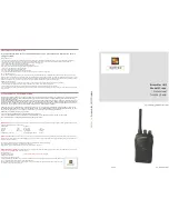
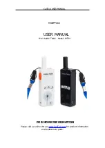
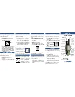
Page 4: ...2 LOCATION OF CONTROLS ...

Page 5: ...res 3 AA LR6 size alkaline batteries not included The battery life is about 30 hours Based on a usage duty of 5 receive 5 talk 90 standby Make sure that the unit is powered OFF before replacing the batteries 1 Pull down the hook and remove the cover ...

Page 6: ... do not dispose of batteries in fire Remove all the batteries when replacing Battery strength You can check the battery strength on the display see below while the unit is in use If the unit beeps intermittently and flashes on the display replace all the batteries with new ones If the unit is left on when the battery is LOW everything except the flashing will disappear from the display Only can be...

Page 7: ...N The unit has 8 operating frequency channels and 38 group codes To talk to others all users in your group must be using the same channel and group code 5 1 Selecting the Operating Channel 5 2 Selecting the Group Code CTCSS ...

Page 8: ...5 3 Backlit LCD Display 5 4 Monitir 5 5 Monitor Sending Receiving Message ...

Page 9: ...5 6 Private Talk 5 7 Call Tones 5 8 Finding a Busy Channel ...

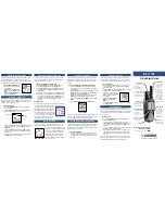
Page 10: ...5 9 Key Lock 5 10 Auto Power OFF ...

Page 11: ...6 USING THE OPTIONS 6 1 To Enjoy Hands Free Operation ...

Page 12: ...6 2 For Use with a Car Battery 7 DISASSEMBLY INSTRUCTIONS ...

Page 13: ... Remove the Battery Cover 2 Rear Cabinet Screws 2X10 A X2 Screws 2X7 B X4 3 RF Block Unsolder the Antenna Lead Wire and shield case Remove the RF Block 4 CPU P C Board Unsolder the Main and Sub Speaker Lead Wires Remove the CPU P C Board ...

Page 14: ...8 HOW TO CHECK SPLASH RESISTANCE 9 CPU DATA ...

Page 15: ......

Page 16: ...10 EXPLANATION OF IC TERMINALS BASE BAND LSI IC11 11 EXPLANATION OF IC TERMINALS CTCSS IC IC13 PIN ...

Page 17: ...12 EXPLANATION OF IC TERMINALS IF IC IC1 13 EXPLANATION OF IC TERMINALS PLL IC IC5 14 TEST MODE SETTING 14 1 FREQUENCY TABLE ...

Page 18: ...y 97 4 12 446 24375 Test mode only 100 0 13 446 49375 Test mode only 103 5 14 446 50625 Test mode only 107 2 15 446 53125 Test mode only 110 9 16 446 54375 Test mode only 114 8 17 446 60625 Test mode only 118 8 18 446 61875 Test mode only 123 0 19 446 64375 Test mode only 127 3 20 131 8 21 136 5 22 141 3 23 146 2 24 151 4 25 156 7 26 162 2 27 167 9 28 173 8 29 179 9 30 186 2 31 192 8 32 203 5 33 2...

Page 19: ...et to confirm the fundamental operation 16 Adjustment and Measurement Points 17 EXPLANATION OF 2 WAY RADIO Different from a telephone 2 Way radio is a basic radio which transmitter and receiver operates alternately Therefore the simultaneous both directed communication Duplex like a cordless telephone is not provided One way half duplex type is employed Transmitting can be done while pushing the T...

Page 20: ... 1 FREQUENCY TABLE Vibrator call As for the vibrator operation the mode of RX side should be preset to make the operation available The vibrator function is available even among different models The vibrator can be operated even by the calling sound or voice of the unit which is not equipped with the vibrator function The calling from other models can activate the vibrator of KX TR 320EXS F Operat...

Page 21: ...IC11 Reverse Frequency 3 4 kHz Reception The receiving voice is output by the demodulated signal AF signal from the RF block and squelch signal AF signal is amplified in IC13 and also the CTCSS signal is divided The detection signal of CTCSS is used for the mute control of signals The output from IC13 is processed in IC11 further and returned by the expander then amplifies the power to drive the s...

Page 22: ...employed as the 2nd local frequency The data from CPU is sent to PLL IC through the serial port and according to this data PLL frequency is set 19 3 TX Operation Circuit Operation The frequency generation circuit of transmitting signal consists of VCO V2 and PLL IC IC5 The output from VCO is amplified at the buffer IC7 and supplied to PLL IC at the same time it is further amplified at the buffer Q...

Page 23: ...t IF intermediate frequency signal Regarding the oscillation frequency of VCO it is controlled by PLL IC IC5 The reference oscillation of X1 21 25MHz and the feed back signal from pin 4 of IC3 is input to this IC Then pin 14 of IC5 outputs the signal to controll VCO V1 as a result of the comparison of these two signals to generate proper VCO frequency That is if the VCO frequency is higher than th...

Page 24: ... led to pin 23 of IC11 and amplified to descramble passing through the filter in the scramble mode TR325 4 Furthermore the signal is returned by the expander to be output from pin 17 then it is amplified at the amplifiers of pin 18 and pin 19 to be output 5 The voice signal is input to the pin 4 of the power amplifier of IC12 for the main speaker and differential outputs from pin 5 and pin 8 to dr...

Page 25: ...z The ratio of dividing frequency output from CPU is programmed to the internal register from pin 7 as the serial data 3 The output from pin 4 of IC7 is input to Q11 RF amplifier The power amplifier Q8 boosts the signal approx 25 dBm and the signal is sent to pin 3 of IC4 antenna switch 4 The signal is output from pin 5 of IC4 passes through the low pass filter and it is transmitted from the anten...

Page 26: ... operation LCD LCD on CPU board consists of 2 common terminals pin 18 19 and 17 segment terminals pin 1 17 and it is driven by CPU directly using the method of 1 2 duty dynamic lighting EEPROM EEPROM on CPU board is connected to CPU directly with the serial signal all kinds of setting items are reserved The default setting and the change of the settings in daily use are always reserved CPU 8 bit c...

Page 27: ...iven at Q15 Battery Voltage Detection Q18 on CPU board is used to check the battery voltage While detecting the voltage the gate of Q18 becomes LOW by CPU port pin 59 the voltage of the battery appears at the drain of Q18 The voltage is divided by R62 and R63 and read by A D input pin 47 then the battery indication appears on LCD External Microphone The external microphone connected to CN1 on CPU ...

Page 28: ...ANT Terminal 21 1 2 Modulation Does Not Work In Transmission 21 2 Transmission Trouble AF Circuit Condition Channel No Setup Standard Modulation 1KHz Input C3V Applied MIC Input Check TXP 3V Pin11 CN5 TX LOW Pin12 CN5 21 2 1 Modulation Does Not Work ...

Page 29: ...4 5V Supplied from External Power Source 21 3 1 Power Supply Will Not Be ON 21 4 Reception Trouble RF Circuit Condition Channel No Setup SSG Frequency Setup Standard Modulation 1KHz C3V Normally Applied CN5 Pin10 RX LOW 21 4 1 Cannot Receive ...

Page 30: ...21 5 Reception Trouble AF Circuit Condition Channel No Setup SSG Frequency Setup Standard Modulation 1KHz C3V Applied AF Signal Pin3 CN4 Check 21 5 1 PTT Mode ...

Page 31: ...21 5 2 Private Mode 22 TERMINAL GUIDE OF IC S TRANSISTORS AND DIODES 23 CABINET AND ELECTRICAL PARTS ...

Page 32: ...24 ACCESSORY AND PACKING MATERIALS ...

Page 33: ...25 TOOL ...

Page 34: ...s 1 The marking RTL indicates that the Retention Time is limited for this item After the discontinuation of this assembly in production the item will continue to be available for a specific period of time The retention period of availability is dependent on the type of assembly and in accordance with the laws governing parts and product retention ...

Page 35: ...safety When replacing any of these components use only manufacture s specified parts 3 The S mark indicates service standard parts and may differ from production parts 4 RESISTORS CAPACITORS Unless otherwise specified All resistors are in ohms K 1000 M 1000k All capacitors are in MICRO FARADS F P F Type Wattage of Resistor 26 1 Base Unit 26 1 1 CABINET AND ELECTRICAL PARTS ...

Page 36: ...10116Z ANTENNA 18 PQHX10907Z REFLECTOR SHEET 19 PQHR10719Z LCD HOLDER 20 PQKK10097Y1 BATTERY COVER S 21 PQDF10094Z SHAFT 22 PQHG10566Z PACKING RUBBER BATTERY 23 PQHG10567Z PACKING RUBBER CABINET 24 PQHS10415Z SHEET 25 PQHS10416Z SHEET 26 PQJC10040Z BATTERY TERMINAL 27 PQJC10041Z BATTERY TERMINAL 28 PQADM0541R22 LIQUID CRYSTAL DISPLAY 29 PQJC10042Z BATTERY TERMINAL 30 PQKE10096Z1 BATTERY LEVER S 31...

Page 37: ...DTC114EU TRANSISTOR SI Q17 2SK1581 TRANSISTOR SI Q18 2SJ461 TRANSISTOR SI Q19 PQVTDTA114EU TRANSISTOR SI DIODES D1 PQVDNNCD56DT DIODE SI S D2 PQVDNNCD56DT DIODE SI S D3 PQVDNNCD56DT DIODE SI S D4 1SS372 DIODE SI D5 MA8150 DIODE SI LEDS LED1 PQVDSML310MT LED S LED2 PQVDSML310MT LED S LED3 LNJ115W8PRA LED JACK SOCKETS CN1 PQJJ1C008Z JACK SOCKET CN2 PQJJ1D019Z JACK SOCKET CN3 PQJJ1B006Z JACK SOCKET C...

Page 38: ...04KBV 0 1 C19 ECUV1C104KBV 0 1 C20 ECUV1A224KBV 0 22 C21 ECUV1H470JCV 47P C22 ECUV1C104KBV 0 1 C23 ECUV1H470JCV 47P C24 ECUV1H223KBV 0 022 C25 ECUV1H821KBV 820P C26 ECUV1A105ZFV 1 C27 ECUV1H333KBV 0 033 S C28 ECUV1H102KBV 0 001 C29 ECUV1H331JCV 330P C30 ECUV1A105ZFV 1 C31 ECUV1H102KBV 0 001 C32 ECUV1C104ZFV 0 1 C33 ECUV1A105ZFV 1 C34 ECUV1C104ZFV 0 1 C35 ECUV1H101JCV 100P C36 ECUV1H103KBV 0 01 C37...

Page 39: ...ECUV1H102KBV 0 001 C182 ECUV1H102KBV 0 001 C183 ECUV1H102KBV 0 001 C184 ECUV1H102KBV 0 001 C185 ECUV1H470JCV 47P C186 ECUV1H102KBV 0 001 C187 ECUV1H470JCV 47P C188 ECUV1H470JCV 47P C189 ECUV1H470JCV 47P C190 ECUV1H470JCV 47P C191 ECUV1H102KBV 0 001 C192 ECUV1H102KBV 0 001 C193 ECUV1H101JCV 100P C194 ECUV1H101JCV 100P C195 ECUV1H102KBV 0 001 C196 ECUV1H333KBV 0 033 S C197 ECUV1H101JCV 100P RF P C B...

Page 40: ...OIL L2 PQLQR4D1R0K COIL L3 MQLRE10NJF COIL L4 MQLRER10JF COIL L5 MQLRE22NJF COIL L6 PQLQR1RW601 COIL L7 PQLQX1A14R3 COIL L8 PQLQX1A14R3 COIL L9 MQLRE12NJF COIL L10 MQLRE5N6JF COIL L11 MQLRE22NJF COIL L12 MQLRE18NJF COIL L13 MQLRE12NJF COIL L14 PQLQR1RW601 COIL L15 PQLQR1RS220 COIL L16 PQLQR1RS220 COIL L20 PQLQX1A14R3 COIL OTHERS CN5 PQJP20B89Z CONNECTOR F1 PQVSSFS446P0 CERAMIC FILTER VC1 PQCVTZV02...

Page 41: ...1k R94 ERJ3GEYJ102 1k R95 ERJ3GEYJ681 680k R96 ERJ3GEYJ102 1k R97 ERJ3GEYJ222 2 2k R98 ERJ3GEYJ180 18k R99 ERJ3GEYJ105 1M R102 ERJ3GEYJ561 560k R103 ERJ3GEYJ272 2 7k R104 ERJ3GEYJ151 150k CAPACITORS C64 ECUV1H102KBV 0 001 C65 ECUV1H102KBV 0 001 C66 ECUV1H100DCV 10P C67 ECUV1H030CCV 3P C68 ECUV1H470JCV 47P C69 ECUV1H102KBV 0 001 C70 ECUV1H101JCV 100P C72 ECUV1H102KBV 0 001 C74 ECUV1H103KBV 0 01 C75...

Page 42: ...UV1H120JCV 12P C105 ECUV1H120JCV 12P C106 ECUV1H103KBV 0 01 C107 ECUV1H150JCV 15P C108 ECUV1H200JCV 20P C109 ECUV1H102KBV 0 001 C110 ECUV1H103KBV 0 01 C112 ECUV1C104KBV 0 1 C113 ECUV1H472KBV 0 0047 C114 ECST0JY106 10 C115 ECUV1H103KBV 0 01 C116 ECST0JY106 10 C117 ECUV1H103KBV 0 01 C118 ECUV1H103KBV 0 01 C119 ECUV1H200JCV 20P C120 ECUV1H020CCV 2P C121 ECUV1H060DCV 6P S C122 ECUV1H040CCV 4P C123 ECU...

Page 43: ...100k R6 ERJ3GEYJ104 100k R7 ERJ3GEYJ222 2 2k R8 ERJ3GEYJ153 15k R9 ERJ3GEYJ103 10k R10 ERJ3GEYJ103 10k R11 ERJ3GEYJ223 22k R12 ERJ3GEYJ473 47k R13 ERJ3GEYJ563 56k R14 ERJ3GEYJ473 47k R15 ERJ3GEYJ123 12k R16 ERJ3GEYJ334 330k R17 ERJ3GEYJ123 12k R18 ERJ3GEYJ103 10k R19 ERJ3GEYJ223 22k R20 ERJ3GEYJ102 1k R21 ERJ3GEYJ223 22k R22 ERJ3GEYJ222 2 2k R23 ERJ3GEYJ223 22k R24 ERJ3GEYJ562 5 6k R25 ERJ3GEYJ153...

Page 44: ...00 0k R50 ERJ3GEYJ105 1M R51 ERJ3GEYJ104 100k R52 ERJ3GEYJ104 100k R54 ERJ3GEYJ103 10k R55 ERJ3GEYJ820 82k R56 ERJ3GEYJ820 82k R57 ERJ3GEYJ104 100k R58 ERJ3GEYJ104 100k R60 ERJ3GEYJ104 100k R62 ERJ3GEYJ104 100k R63 ERJ3GEYJ104 100k R64 ERJ3GEYJ331 330k R65 ERJ3GEYJ101 100k 26 1 4 TOOL Ref No Part No Part Name Description Remarks ZZ1 PQZZ20K4Z EXTENTION CORD 27 CIRCUIT BOARD RF P C Board 28 SCHEMAT...

Page 45: ...ÒË ÍÉ õìòëÊ ÝíÊ ÙÒÜ Þó ÔÑÝÕ ÍÉ ÍÝßÒ ÍÉ ÓÑÒ ÌÑÎ Ó Ý ÜÑÉÒ ÍÉ Ó ÍÐõ Ó ÍÐó ÍËÞ ÍÐó ÚÔ Ð ÍÉ ÍËÞ ÍÐõ Öï ÌÛÍÌ ËÐ ÐÌÌ Öï ÙÒÜ ßÙÒÜ ÓÑÌÑÎ ÊÝï ÍÏ ÊÎî ÜÝìòëÊ ÜÝ ÐÑÉÛÎ ÍËÐÐÔÇ ßÚ Ù ïðÊ ïð Ú Ú Ý ÌÐóßÒÌ Ô Ü Ó Ýó ÒÐËÌ õ ó ...

Page 46: ... Ýï Ýí Ýî Ýì Ýë ...

Page 47: ...øí øé øë øè øç øê øì øî ßÓÐî ÍÓÚ ßÓÐì ÞÐÚ ÑÍÝ Ð Ü ª Í ÎÈ ØÐÚ ßÓÐî ßÓÐí Ü ÎÈ ÔÐÚ õÊÎí Û ÊÎì Ü ...

Page 48: ... Ýì Ýé Ýë øê øê øë ÑÚÚ ÑÒ øé øè ...

Page 49: ...ßÓÐï ßÓÐí Ô Í ß ÌÍÏ ØÐÚï ÑÍÝ Ð Ü ª ÌÍÏ ÔÐÚï ÌÈ ØÐÚ õÊÎï ßÓÐï Ý Ô Í Ú Í Ð ó ...

Page 50: ... Ôïì Ýèí Ôê Ýïðî Îèí Ýèê Ýéé Ýïîè Ýé Êî Êï Ýïïì ÝÒë Ýë Ïïì Ýí Ýèè Ýèð Ýçð Îèì Ýïïé Îèë Ýïðê Ýïíí Ýïîç Îçï Ýïîì Ýïíé Ïïî ÙÒÜ ßÒÌ ßÒÌ ÍÏ Ýêì Îïðì Ôî Ýçë Ýïíï Ýïìî Ýïîï Ýïíê Ôïí Ýïìì Ôç Ýïìï Ýïðç Ýïðë Îçì Îçë Îêè Ôì Ýïðí Ýïðï Ôé Ôè Ôîð Úï Èï Ïï Ýéê Ýéè Ýèï Ýèì Ýçï Ýçè Ýï Îéê Ýêë ÊÝï Îéè Ýèé Îèð Ýçî Ýéë Îêç Ýéç Ýèë Îéç Îèï ÓÑÌÑÎ Ýçê ...

Page 51: ...ð ïòçè é è ß ð ð ð ð ð ïòðì í îòìé îòï îòèî ïòçè ð ð îòéé îòï ïòéç îòèî ð ð í ð ð ð øîòç øîòç øð øð øð øð øð øî øð øð ðòçë ð ïòí ð îòíè îòé îòéì ðòèè ðòèè ðòèè ðòèç ðòé ðòéë ðòí ïòéé îòï ðòèì ðòêé ðòêë ïòï îòï ðòì ðòì ð ðòçë îòéì ðòíé ðòèé Ýï Ýí Ýî Ýì Ýé Ýë ...

Page 52: ...Ó Ý Ó ñÍßÞ ÍÐ ÍßÞ ÍÐ ...

Page 53: ...ÝÒì ï ïç îð î Ýëë Ýïèê Ø Ó Ý Þ õ Þ ó Ýëé ÐÌÌ Ýïèï Îëê Ýëì Îç Ýìé Ýìè Öï ÔÛÜí ÍÝßÒ Ýî Îïï Î Ù Ýìç Ýëí Ýêí ìð îï ïíèð ÓÑÒ ÌÑÎ ÝßÔÔ Ý ÓÛÒË ÚÔ Ð ...

Reviews: