background image


Model No.   

KX-TDA0490

16-Channel VoIP Gateway Card

Getting Started

Thank you for purchasing a Panasonic 16-Channel VoIP Gateway Card.
Please read this manual carefully before using this product and save this manual for future use.

Summary of Contents for KX-TDA0490

Page 1: ...TDA0490 16 Channel VoIP Gateway Card Getting Started Thank you for purchasing a Panasonic 16 Channel VoIP Gateway Card Please read this manual carefully before using this product and save this manual for future use ...

Page 2: ...ateway Card 27 3 2 3 Assigning the IP Address 28 3 2 4 Assigning the Hunt Pattern 29 3 2 5 Programming the Address Translation Table 31 3 2 6 Downloading the Address Translation Table from the VoIP Gateway Card 34 3 2 7 Rebooting the VoIP Gateway Card 35 3 2 8 Confirming the IP Address Assignment 36 3 3 Programming the VoIP Gateway Card in the Chicago Office 37 4 Programming the PBX 41 4 1 Program...

Page 3: ...Getting Started 3 C Initialisation of the VoIP Gateway Card 63 C1 Initialising the VoIP Gateway Card 64 D Using the KX TDA0490 and KX TDA0480 in One Network 67 D1 Considerations in Installation 68 ...

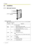
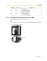
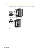
Page 4: ...4 Getting Started ...

Page 5: ...ateway Card designed to be easily integrated into existing IP networks seamlessly bridges Public Switched Telephone Network PSTN and analogue telephones with digital data networks without interrupting pre existing data communications Because communications do not take place over conventional telephone networks the high cost of long distance communications is virtually eliminated ...

Page 6: ...or fax signals into IP packets for transmission On the incoming side it reverses this process and translates the packets back into appropriate voice or fax signals PSTN Public Switched Telephone Network IP Network PSTN Voice signals are converted into IP packets Router Switching Hub Hybrid IP PBX with a VoIP Gateway Card Other data packets Voice data packets IP packets are converted back into voic...

Page 7: ...r own VoIP network PSTN Public Switched Telephone Network IP Network Chicago Office PBX Code 41 PSTN Trunk Number 9 TIE Line Access Number 7 PSTN Local Telephone 123 4567 Extn 301 300 399 PBX Code 35 PSTN Trunk Number 9 TIE Line Access Number 7 Extn 201 200 299 Local Telephone 456 7890 G3 Fax Extn 501 500 599 G3 Fax Extn 601 600 699 Default Gateway IP 200 45 11 1 Subnet Mask 255 255 255 0 Card IP ...

Page 8: ...lity to use the enhanced networking features of the PBX for more information about these features refer to the relevant sections of the Hybrid IP PBX documentation Firewall A firewall protects the internal networks of an organisation against unauthorised penetration from outside When routing a VoIP network through a firewall some performance degradation may result If for practical reasons you must...

Page 9: ...y the destination number of the called party to call through PBXs at different locations hence there are fewer digits to dial than with the PBX code method To employ the extension number method no 2 PBXs can have extensions sharing the same number For example if one PBX in the network has an extension whose number is 201 no other PBX can have an extension with the same number 201 Los Angeles Offic...

Page 10: ...scription PBX Code 35 41 A unique number ranging from 1 to 7 digits assigned to identify each PBX within a network In this example for convenience each PBX code corresponds to the last portion of the IP address of its card that is because the Los Angeles office card has the IP address 200 45 11 35 Los Angeles PBX code is 35 TIE Line Access Number 7 7 An access number to use the TIE line service PS...

Page 11: ... to access the destination However for example setting the remaining digits to 7 does not mean that the user must dial all 7 digits when making a call See the example on the right Card IP Address The IP address of each card in the network as the access destination Los Angeles Office PBX Code 35 Chicago Office PBX Code 41 Extn FAX Extn PSTN Access Extn FAX Extn PSTN Access Leading Number 352 355 35...

Page 12: ...N Public Switched Telephone Network IP Network PBX Code PSTN Trunk Number TIE Line Access Number Extension Number Local Telephone G3 Fax Extension Number Subnet Mask IP Address Card IP Address Default Gateway IP Address Subnet Mask Address PBX Numbering PBX Code TIE Line Access Number PSTN Trunk Number Extension Number Fax Extension Number Card IP Address Extensions Leading Number Remaining Digits...

Page 13: ... in the PBX This section describes the physical installation process of the VoIP Gateway Card covering the following topics 1 installing the card in the PBX and 2 connecting the card to a network device using a Category 5 CAT5 Ethernet cable ...

Page 14: ...en ON Normal all ports are idle Green Flashing 60 times per minute Normal a port is in use Red ON Fault includes reset Red Flashing 60 times per minute Out of Service ONLINE Green On line status indication ON On line mode OFF Off line mode Flashing Maintenance mode Note If the LINK indicator is OFF the ONLINE indicator will also be OFF ALARM Red Alarm indication ON Alarm OFF Normal VoIP BUSY Green...

Page 15: ...BX Note The illustrations of the PBX shown in the installation procedure are based on the KX TDA600 1 Insert the card along the guide rails LINK Green Link status indication ON Normal connection OFF Connection error DATA Green Data transmission indication ON Data transmitting OFF No data transmitted Indication Colour Description Guide Rail ...

Page 16: ...h the release lever in the direction of the arrow so that the card engages securely with the connector on the back board 3 Turn the 2 screws clockwise to fix the card in place Note Make sure the screws are tightened to earth the card securely Release Lever Back Board Screws ...

Page 17: ...outer or PC use an Ethernet cross cable Note Use only CAT5 Ethernet cable for connection 2 2 1 Attaching a Ferrite Core to the Cable When connecting the VoIP Gateway Card to a network device first attach a ferrite core included with the card to the cable 1 Wrap the cable once around the ferrite core leaving 5 cm between the ferrite core and the connector 2 Close the case of the ferrite core If you...

Page 18: ...en assigning a new IP address to the VoIP Gateway Card for the first time connect a PC directly to the card using an Ethernet cross cable 1 Connect the Ethernet cable to the RJ45 connector of the card 2 Connect the other end of the cable to the PC Ethernet Cross Cable PC RJ45 ...

Page 19: ...J45 connector of the card 2 Connect the other end of the cable to the remote LAN equipment Connecting to a switching hub Notes Make sure to connect to a switching hub Do not connect to a repeater hub as this will result in degradation in speech quality Also make sure to set the port of the switching hub that connects to the card to operate under Auto Negotiation mode This will help assure error fr...

Page 20: ...2 2 Cable Connection 20 Getting Started ...

Page 21: ...o through the whole programming process of a VoIP Gateway Card at one location in the network then start programming the other cards at different locations Based on the theoretical network illustrated previously in this manual this section demonstrates the procedure to programme the cards in the Los Angeles and Chicago offices ...

Page 22: ...shots reprinted with permission from Microsoft Corporation 3 1 1 Preparing the PC To prepare for programming using the IP GW16 Maintenance Utility configure your PC by 1 assigning an IP address that belongs to the same network as that of the VoIP Gateway Card and 2 choosing the appropriate options for the Internet properties Note The procedure below is based on the Windows XP operating system as a...

Page 23: ... network However if the network has a proxy server installed you must apply appropriate proxy settings to your PC In this case follow the steps below in substitution for step 5 above 4 a Click the Connections tab b Click Never dial a connection c Click LAN Settings 5 a Click to clear all check boxes b Click OK Your PC is now ready for programming through direct access to the card 5 Click Advanced ...

Page 24: ...Preparations 24 Getting Started 6 a Under Do not use proxy server for addresses beginning with type the IP address of the card b Click OK Your PC is now ready for programming the card through an IP network ...

Page 25: ...es Office 3 2 1 Starting the IP GW16 Maintenance Utility Make sure that a PC is connected directly to the VoIP Gateway Card with an Ethernet cross cable see 2 2 2 Connection for Programming The card should not be connected to the LAN at this point 1 Start Internet Explorer from the Start menu 2 a In the Address box of Internet Explorer type http 192 168 1 200 default IP address of the card b Press...

Page 26: ...orer you cannot log in again for the period of time specified by the parameter Programming Auto Disconnect Time default 10 min For the log out procedure and Programming Auto Disconnect Time setting refer to 2 5 2 Log Out and 2 3 2 Maintenance Settings of the VoIP Gateway Card Programming Guide respectively The main menu appears Note For readability of the text on the screen it is recommended that ...

Page 27: ...etting Started 27 3 2 2 Changing the Status of the VoIP Gateway Card When programming the VoIP Gateway Card place the card in the STOP status 1 Click 2 1 Change RUN STOP status in the main menu 2 a Click STOP for Status after changing b Click OK 3 Click OK 4 Click OK ...

Page 28: ...over the VoIP network The specific setting values are based on the table under IP Addressing Information in 1 2 2 Numbering Plan Example Note For more details about IP address assignment refer to 2 2 1 Network Parameters of the VoIP Gateway Card Programming Guide 1 Click 1 1 Network Settings General in the main menu 2 a In the IP Address box type 200 45 11 35 b In the Subnet Mask box type 255 255 ...

Page 29: ... hunt pattern determines how to route incoming calls through the VoIP Gateway Card to the PBX 1 Click 1 5 Hunt Pattern for Incoming Calls in the main menu 2 a In the Hunt Pattern No box type 1 A hunt pattern will be created with this numbering b In the Receive Leading Number box type 35 PBX code c Click ENTRY d Click OK ...

Page 30: ...teway Card in the Los Angeles Office 30 Getting Started Note For more details about hunt pattern assignment refer to 2 2 5 Hunt Pattern Parameters of the VoIP Gateway Card Programming Guide 3 Confirm your entry and then click OK ...

Page 31: ...he same information see 3 2 6 Downloading the Address Translation Table from the VoIP Gateway Card and Uploading Address Translation Table to the VoIP Gateway Card in 3 3 Programming the VoIP Gateway Card in the Chicago Office Note The address translation table created for the KX TDA0490 can be shared with the KX TDA0484 and KX TDA3480 The procedure below demonstrates the process of programming th...

Page 32: ...aving the value 0 for Group No means that the card does not belong to any gateway group Grouping is useful when installing multiple cards at one location For details refer to 2 2 6 Address Translation Table GW Entry of the VoIP Gateway Card Programming Guide e Click ENTRY 4 Do the following to configure the gateway entry for the Chicago office a In the GW No box type 1 b In the Comment box type Ch...

Page 33: ... 1 6 2 DN2IP Entry 8 Do the following to configure the Los Angeles extensions a In the Leading Number box type 352 PBX code 35 extension starting digit 2 b In the Remaining Number of Digits box type 2 2 digits to dial 00 to 99 following the leading number c Click GW for GW No Group No Selection d In the GW No Group No box type 0 the gateway entry for the card e Click ENTRY 9 a Referring to step 8 ...

Page 34: ...VoIP network see Uploading Address Translation Table to the VoIP Gateway Card in 3 3 Programming the VoIP Gateway Card in the Chicago Office so that all the cards can communicate with each other over the network Note For more details about downloading the address translation table refer to 2 4 4 Download of Address Translation Table of the VoIP Gateway Card Programming Guide 1 Click 3 4 Download o...

Page 35: ...y Card in the Los Angeles Office Getting Started 35 3 2 7 Rebooting the VoIP Gateway Card For all the changes to the parameters to become effective you must reboot the VoIP Gateway Card 1 Click REBOOT in the main menu 2 Click REBOOT ...

Page 36: ...ress settings of the PC to the following values IP address 200 45 11 100 Subnet Mask address 255 255 255 0 2 Start Internet Explorer from the Start menu 3 In the Address box of Internet Explorer type http 200 45 11 35 the new IP address of the card 4 Press the ENTER key on the keyboard If you can log in then the card has been successfully programmed After you have confirmed that the card has been ...

Page 37: ...ne downloaded from the card in the Los Angeles office already contains the information for the entire network You can simply upload the address translation table from the Los Angeles office and the cards can communicate with each other on the network Starting the IP GW16 Maintenance Utility Changing the Status of the VoIP Gateway Card 1 Start Internet Explorer from the Start menu 2 a In the Addres...

Page 38: ...ice requires a different PBX code from the card in the Los Angeles office 1 Click 1 1 Network Settings General in the main menu 2 a In the IP Address box type 199 176 64 41 b In the Subnet Mask box type 255 255 255 0 c In the Default Gateway box type 199 176 64 1 d Click OK 3 Confirm your entry and then click OK 1 Click 1 5 Hunt Pattern for Incoming Calls in the main menu 2 a In the Hunt Pattern N...

Page 39: ...ds must share the same address translation table Follow the procedure below to upload the address translation table downloaded from the card in the Los Angeles office see 3 2 6 Downloading the Address Translation Table from the VoIP Gateway Card to the card in the Chicago office 3 Confirm your entry and then click OK 1 Click 3 3 Upload of DN2IP data PC VoIP Gateway in the main menu 2 a Click Brows...

Page 40: ...6 64 100 Subnet Mask address 255 255 255 0 2 Start Internet Explorer from the Start menu 3 In the Address box of Internet Explorer type http 199 176 64 41 the new IP address of the card 4 Press the ENTER key on the keyboard If you can log in then the card has been successfully programmed After you have confirmed that the card has been successfully programmed it is strongly recommended that you dow...

Page 41: ...Getting Started 41 Section 4 Programming the PBX This section details the procedure to programme the PBX to use the VoIP Gateway Card ...

Page 42: ... in the Chicago office with the appropriate setting values Notes It is assumed that you have already installed the Maintenance Console KX TDA100 KX TDA200 KXTDA Maintenance Console KX TDA600 KX TDA600 Maintenance Console in your PC The screenshots shown in the installation procedure are based on the KX TDA600 Maintenance Console The contents and design of the software are subject to change without...

Page 43: ...tem b Click Numbering Plan c Click Main d Click the Features tab e In the TIE Line Access box type the dialling number f Click OK 7 a From the System Menu click Private Network b Click TIE Table c In the Own PBX Code box type 35 the PBX code of the local PBX in the network d In the first unused Leading Number box type 41 the PBX code of the remote PBX in the network e In the corresponding Trunk Gr...

Page 44: ...rd to display the menu of options d Click OUS You will see a confirmation message e Click OK f Move the mouse pointer over the installed VoIP Gateway Card to display the menu of options g Click Card Property 9 a Select the preferred En bloc Dialling setting Overlap default or En bloc 1 b Click OK 10 a Move the mouse pointer over the installed VoIP Gateway Card to display the menu of options b Clic...

Page 45: ...Getting Started 45 Appendix A Guidance for VoIP Installation ...

Page 46: ...ed bandwidth for one VoIP channel is shown in the tables below for more details refer to 2 2 3 Voice Communication Parameters in the VoIP Gateway Card Programming Guide Required Bandwidth for One VoIP Channel The required bandwidth depends on what combination of CODEC and packet sending interval is used Keep in mind the following points about the type of CODEC and packet sending interval in terms ...

Page 47: ...that all cards in a VoIP network have the same packet sending interval Additional Information As described above it is possible to control the required bandwidth by selecting a certain combination of CODEC and packet sending interval However it is also possible to control required bandwidth by limiting the number of available VoIP channels The card supports a total of 8 ports each having 2 separat...

Page 48: ...ture of the existing network to see if a VoIP network can be implemented Below are the points that should be taken into your evaluation Is it possible to have static IP addressing Because the maintenance of the VoIP Gateway Card is carried out from a personal computer PC through an IP network the card must be assigned a static IP address Static IP addressing must be made possible even when the DHC...

Page 49: ...ter provide access to the IP network In a dual network 2 routers provide access to the IP network as shown in the diagram below However the VoIP Gateway Card cannot take the advantage of having 2 routers as access points to the IP network For example if router A whose IP address is assigned as the default gateway IP address of the card fails VoIP communications are no longer possible the card is n...

Page 50: ...ds of a call A huge degradation in speech quality will be produced when calls are made through multiple IP networks as shown below therefore it is recommended that you avoid establishing a VoIP network in this fashion IP Network 1 IP Network 2 PSTN BRI QSIG etc IP Network 1 IP Network 2 ...

Page 51: ...etwork to see if a VoIP network can be implemented Below are the points that should be taken into your evaluation Can the firewall pass packets from the VoIP Gateway Card If the VoIP network contains a firewall the firewall must be configured appropriately to allow VoIP packets which are listed in the table below to pass through the network without being blocked by filtering For more information c...

Page 52: ...oice packets and lower the rate of loss and delays during transmissions hence improving speech quality It is strongly recommended that you use this feature especially in networks where traffic is heavy Typically a router identifies what packets to pass in priority by checking the value in the ToS field of the header of IP packets The VoIP Gateway Card has the ability to set the ToS field of outgoi...

Page 53: ... kbps Available bandwidth for VoIP kbps Required bandwidth for VoIP kbps p 46 No Question Answer Memo Ref 2 a Is it possible to have static IP addressing Yes No p 48 2 b Is network address translation NAT NAPT disabled Yes No p 49 2 c Does only a single router provide access to the IP network Yes No p 49 2 d Is there only a single IP network between 2 ends of a call Yes No p 50 2 e Is the card loc...

Page 54: ...t the port of the switch that connects to the card should be set to operate under Auto Negotiation mode Yes No Model of the switch p 52 3 c Are Category 5 CAT5 cables used Yes No p 52 No Question Answer Memo Ref 4 Can the router or switch be configured to use priority control features Yes No Model of the router switch VoIP Gateway Card s ToS field setting p 52 No Question Answer Memo Ref ...

Page 55: ...Getting Started 55 Appendix B Alternative Numbering Plan Example ...

Page 56: ...gured for the extension number method PSTN Public Switched Telephone Network IP Network Chicago Office PSTN Trunk Number 93 VoIP Gateway Trunk Access Number 803 PSTN Local Telephone 123 4567 Extn 301 300 399 PSTN Trunk Number 92 VoIP Gateway Trunk Access Number 802 Extn 201 200 299 Local Telephone 456 7890 G3 Fax Extn 501 500 599 G3 Fax Extn 601 600 699 Default Gateway IP 200 45 11 1 Subnet Mask 2...

Page 57: ...9 176 64 1 Identifies the IP address of the primary gateway typically a router or similar device that exchanges IP packets with the other gateways on the VoIP network Subnet Mask Address 255 255 255 0 255 255 255 0 Defines which digits of an IP address are used for the network address and the host address at each network location A card IP address must fall within the same subnet as that of the de...

Page 58: ...o Los Angeles To extension 201 via VoIP network To local telephone 456 7890 via VoIP network through local PSTN PBX Connection Information Los Angeles Office Chicago Office Extn FAX Extn PSTN Access Extn FAX Extn PSTN Access Leading Number 2 5 92 3 6 93 Remaining Digits 2 2 7 2 2 7 Card IP Address 200 45 11 35 199 176 64 41 Dial 301 extension no Dial 93 Dial 802 Dial 123 4567 VoIP Gateway trunk ac...

Page 59: ...sections provide specific steps that require different setting values The steps other than those provided here have common setting values and are therefore omitted from this explanation B2 1 Programming the VoIP Gateway Card The hunt patterns and address translation table need different setting values for the extension number method as shown in the screen shots provided below Programming the VoIP ...

Page 60: ...alues shown below following the procedure in 3 2 5 Programming the Address Translation Table Programming the VoIP Gateway Card in the Chicago Office Create hunt patterns with the setting values shown below following the procedure in Assigning the Hunt Pattern under 3 3 Programming the VoIP Gateway Card in the Chicago Office ...

Page 61: ...method following these steps After programming the PBX in the Los Angeles office follow the same procedure to programme the PBX in the Chicago office with the appropriate setting values Step 6 Assign the PSTN trunk access number In the Idle Line Access Local Access box type 92 for Los Angeles office PSTN access Step 7 Assign the leading number used to reach the extensions of the remote PBX In the ...

Page 62: ...he remote PBX In the Leading Number box type 3 for the Chicago office extensions 6 for the Chicago office fax extensions and 93 for Chicago office PSTN access Note Do not set any value in the Own PBX Code box After the above step follow the procedure in 4 1 Programming the PBX in the Los Angeles Office starting from step 8 ...

Page 63: ...Getting Started 63 Appendix C Initialisation of the VoIP Gateway Card ...

Page 64: ...n password to the factory default 1 Install the card to the PBX and then turn on the power to the PBX 2 Using the Maintenance Console confirm that the card is in service INS 3 Set the System Initialise Switch to the SYSTEM INITIALIZE position CAUTION Do not press the Reset Button nor turn the power off then on while the System Initialise Switch is in this position Doing so will initialise the PBX ...

Page 65: ...C1 Initialising the VoIP Gateway Card Getting Started 65 5 Return the System Initialise Switch to the NORMAL position ...

Page 66: ...C1 Initialising the VoIP Gateway Card 66 Getting Started ...

Page 67: ...Getting Started 67 Appendix D Using the KX TDA0490 and KX TDA0480 in One Network ...

Page 68: ...k you must add it as an Other Unit in a Unit Group network when programming with the MCS as shown below Note For programming instructions and other information about the KX TDA0480 refer to the documentation for the KX TDA0480 Restrictions on Feature Compatibility Some restrictions exist when using the KX TDA0490 with the KX TDA0480 as detailed below CLIP service is the only QSIG service available...

Page 69: ...D1 Considerations in Installation Getting Started 69 ...

Page 70: ... material is copyrighted by Panasonic Communications Co Ltd and may be reproduced for internal use only All other reproduction in whole or in part is prohibited without the written consent of Panasonic Communications Co Ltd 2005 Panasonic Communications Co Ltd All Rights Reserved PSQX3945YA KK0805AH1076 ...

Page 71: ...DA0490 16 Channel VoIP Gateway Card Programming Guide Thank you for purchasing a Panasonic 16 Channel VoIP Gateway Card Please read this manual carefully before using this product and save this manual for future use ...

Page 72: ...ry 37 2 2 8 Initialisation 41 2 3 Maintenance 42 2 3 1 Status Control 42 2 3 2 Maintenance Settings 43 2 3 3 Diagnosis 46 2 3 4 Log Information 47 2 4 Data Management 48 2 4 1 Upload of Configuration Data 48 2 4 2 Download of Configuration Data 50 2 4 3 Upload of Address Translation Table 51 2 4 4 Download of Address Translation Table 53 2 5 Others 54 2 5 1 Reboot 54 2 5 2 Log Out 55 3 Installer F...

Page 73: ...P GW16 Maintenance Utility Programming of the VoIP Gateway Card is carried out through a web programming utility called the IP GW16 Maintenance Utility This section provides the start up procedure for the IP GW16 Maintenance Utility ...

Page 74: ...rks Microsoft is either a registered trademark or trademark of Microsoft Corporation in the United States and or other countries All other trademarks identified herein are the property of their respective owners Screen shots reprinted with permission from Microsoft Corporation 1 Run Internet Explorer from the Start menu 2 In the Address box of Internet Explorer type http 192 168 1 200 192 168 1 20...

Page 75: ...ium If you finish a programming session without logging out from the card e g quitting Internet Explorer or returning to the log in screen with the Back button of Internet Explorer you cannot log in again for the period of time specified by the parameter Programming Auto Disconnect Time default 10 min For the log out procedure and Programming Auto Disconnect Time setting refer to 2 5 2 Log Out 3 4...

Page 76: ...1 1 Starting the IP GW16 Maintenance Utility 6 Programming Guide ...

Page 77: ...Programming Guide 7 Section 2 Administrator Functions This section provides operating instructions for the IP GW16 Maintenance Utility when logged in as the Administrator ...

Page 78: ...2 1 Main Menu for the Administrator 8 Programming Guide 2 1 Main Menu for the Administrator The IP GW16 Maintenance Utility provides the following menu to a user logged in as the Administrator ...

Page 79: ...ranslation Table GW Entry 2 2 7 Address Translation Table DN2IP Entry 1 7 Initialization 2 2 8 Initialisation Menu Section Reference 2 1 Change RUN STOP status 2 3 1 Status Control 2 2 Maintenance Settings 2 3 2 Maintenance Settings 2 3 Diagnosis 2 3 3 Diagnosis 2 4 Log Information 2 3 4 Log Information Menu Section Reference 3 1 Upload of Configuration data PC VoIP Gateway 2 4 1 Upload of Configu...

Page 80: ...e during the session you can Click ALL CLEAR to return all parameters to their previous values Click MENU to return to the main menu see 2 1 Main Menu for the Administrator Click LOGOUT to log out from the IP GW16 Maintenance Utility see 2 5 2 Log Out 3 Click OK You will see a confirmation screen Note If your entry contains an invalid value you will be prompted to correct your input Enter correct ...

Page 81: ...t your network administrator 255 255 255 0 Any address is valid Default Gateway Specifies the default gateway IP address of the card For more information consult your network administrator 0 0 0 0 Same as the parameter IP Address except that the address 0 0 0 0 is allowed Parameter Description Default Value Range DHCP Server Specifies the use of a DHCP server For details refer to Detailed Explanat...

Page 82: ...ng Port No Specifies the port number for connectionless tunnelling between cards at different locations in a QSIG network Generally there is no need to change the default value Notes Connectionless tunnelling enables the PBXs on a QSIG network to use enhanced networking features For more information about these features refer to the relevant sections of the Hybrid IP PBX documentation If you are u...

Page 83: ...rd from a pool of IP addresses that is defined in advance For more information about DHCP server settings consult your network administrator In addition it is also necessary to specify the values for the parameters under IP Address Settings as they will be assigned by the DHCP server ...

Page 84: ...heir previous values Click MENU to return to the main menu see 2 1 Main Menu for the Administrator Click LOGOUT to log out from the IP GW16 Maintenance Utility see 2 5 2 Log Out 3 Click OK You will see a confirmation screen Note If your entry contains an invalid value you will be prompted to correct your input Enter correct values for the parameters shown in red and try again 4 Confirm your entry ...

Page 85: ...n an H 323 protocol suite Generally there is no need to change the default value 1720 1 to 65535 H 245 Port No Specifies the port number for the H 245 protocol negotiation of channel usage and capabilities in an H 323 protocol suite 32 consecutive ports starting with the specified port will be used by default 1721 to 1752 Generally there is no need to change the default value 1721 1 to 65504 RAS P...

Page 86: ...ty CODEC set 1st G 729A 2nd No default 3rd No default 4th No default G 723 1 G 729A G 711Mu G 711A Parameter Description Default Value Range Gatekeeper Specifies the use of a gatekeeper For details refer to Detailed Explanations Don t use Use Don t use Primary Gatekeeper IP Address Specifies the IP address of the primary gatekeeper 192 168 1 3 The following addresses are invalid Class D addresses ...

Page 87: ...gatekeeper When using a gatekeeper make sure to choose a compatible model For more information about gatekeeper compatibility with the card consult a certified dealer Gatekeeper Connection Checking Interval min 0 1440min Specifies the time in minutes between periodic checks of connection to the gatekeeper When the primary gatekeeper fails these checks can detect the failure In this case the connec...

Page 88: ...menu 2 Assign each parameter referring to the descriptions below At any time during the session you can Click ALL CLEAR to return all parameters to their previous values Click MENU to return to the main menu see 2 1 Main Menu for the Administrator Click LOGOUT to log out from the IP GW16 Maintenance Utility see 2 5 2 Log Out 3 Click OK ...

Page 89: ...ion at varied timings This is referred to as jitter and it can cause degradation in speech quality To compensate for jitter problems the jitter buffer accumulates the packets temporarily for processing The parameters below are used to adjust the size of the jitter buffer However in general there is no need to change the default values Jitter buffer Settings G 711 G 729A G 723 1 for Voice Parameter...

Page 90: ... 30 60 90 G 729A Packet Sending Interval ms 20 20 30 40 60 G 711 Packet Sending Interval ms 20 20 30 40 60 Parameter Description Default Value Range Echo Canceller Specifies the length of the echo canceller in milliseconds when using the echo cancellation feature G 168 or disables the feature Echo is the audible duplication of a caller s voice on the return path when echo exists the caller hears h...

Page 91: ... 723 1 G 729A and G 711 The VAD conserves bandwidth by detecting silent periods during a call and suppressing the packets of silence from being sent to the network Notes To use the VAD feature for a certain CODEC be sure to enable it for that CODEC on both the local and remote cards To use the VAD feature between the KX TDA0490 and KX TDA3480 KX TDA0484 you must enable it for the G 723 1 CODEC Oth...

Page 92: ...work For details refer to Detailed Explanations Don t use Use Don t use DTMF Detection Level dB 46 0dB Specifies the level in decibels of DTMF detection Generally there is no need to change the default value 20 46 to 0 Parameter Description Default Value Range Bit 0 Bit 8 IP Header Version IHL Total Length 0 0 0 0 1 1 1 1 0 0 1 1 0 0 1 1 0 1 0 1 0 1 0 1 Priority 0 Priority 1 Priority 2 Priority 3 ...

Page 93: ... 60 ms 90 ms G 711 87 2 kbps 79 5 kbps 75 6 kbps 71 7 kbps G 729A 31 2 kbps 23 5 kbps 19 6 kbps 15 7 kbps G 723 1 5 3 kbps 20 8 kbps 13 1 kbps 10 5 kbps G 723 1 6 3 kbps 21 9 kbps 14 1 kbps 11 6 kbps Bit 0 Bit 8 IP Header Version IHL Total Length Bit 15 Reserved Reserved Bit 32 IP Packet Type of Service DSCP 0 DSCP 1 DSCP 62 DSCP 63 0 0 1 1 0 0 1 1 0 0 1 1 0 0 1 1 0 0 1 1 0 1 0 1 Bit 0 Bit 8 IP He...

Page 94: ...led the sending of packets is delayed by approximately 30 ms Therefore it is recommended that you disable this feature unless DTMF detection is necessary FAX Signal Detection When sending fax signals using a CODEC other than G 711 the signals cannot be received accurately at the destination because they are coded decoded over the VoIP network in the same way as voice signals To compensate for this...

Page 95: ...484 card For more information about this feature refer to the KX TDA3480 KX TDA0484 Programming Guide Fax communications cannot take place between the KX TDA0490 and KX TDA0480 VoIP Gateway Cards Fax communications in the Super G3 mode are not guaranteed ...

Page 96: ...lues for the parameters shown in red and try again 4 Confirm your entry and click OK To return to the previous screen click CANCEL Parameter Descriptions The parameters indicated with must be changed while the VoIP Gateway Card is in the STOP status see 2 3 1 Status Control The changes do not have to be followed by a reboot to become effective Dialing Settings Parameter Description Default Value R...

Page 97: ...Generally there is no need to change the default value 0 to 9 Parameter Description Default Value Range Network CODEC of IP PBX The value of this parameter is set automatically as appropriate to the setting of the PBX There is no need to change the value Not applicable G 711 Mu Law G 711 A Law Parameter Description Default Value Range ...

Page 98: ...vious values Click MENU to return to the main menu see 2 1 Main Menu for the Administrator Sort the hunt patterns in the table at the bottom of the screen a Click the desired sort key and sort order from the Sort Option lists b Click SORT Delete the desired hunt pattern from the table at the bottom of the screen a Select the appropriate check box for the hunt pattern you want to delete b Click DEL...

Page 99: ...n Default Value Range Port1 8 Assigns a hunt group to a VoIP gateway port For details refer to Detailed Explanations Hunt group 1 Hunt group 1 to 8 Parameter Description Default Value Range Hunt Pattern No Specifies the number for the hunt pattern to be created When changing the current settings of an existing hunt pattern first delete the hunt pattern and then re create with new values No default...

Page 100: ...rovide 2 different methods of hunt pattern programming Hunt Group Priority1 Specifies the hunt group to which incoming calls are directed first 1 1 to 8 Hunt Group Priority2 Priority8 Specifies the hunt group to which incoming calls are directed when the hunt group specified in the previous priority level is busy 1 to 8 disable Parameter Description Default Value Range IP Network VoIP Gateway Card...

Page 101: ...ion group B Hunt Group Hunt Pattern Entry Port1 Hunt group 1 Port2 Hunt group 1 Port8 Hunt group 1 Hunt Pattern No 1 Receive Leading Number 9 Hunt Group Priority1 1 Hunt Group Priority2 Hunt Group Priority8 IP Network Extn Group A Extn 101 Extn 199 Extn Group B Extn 201 Extn 299 Dials 950 101 Dials 950 102 Dials 950 103 Dials 950 104 VoIP Gateway Card Port 1 PBX PBX Code 950 Channel 1 Channel 2 Po...

Page 102: ...orts consisting of ports 5 to 8 When all 8 channels in the first group of ports are being used this configuration rejects the 9th call to extension group A However the other 8 channels in the second group of ports remain available to route calls to extension group B Hunt Group Hunt Pattern Entry 1 Hunt Pattern Entry 2 Port1 Hunt group 1 Port4 Hunt group 1 Port5 Hunt group 2 Port8 Hunt group 2 Hunt...

Page 103: ...above details the configuration to route incoming calls to 2 separate hunt groups each of which is associated with an individual extension group However note that various other types of configurations are possible For example it is possible to route calls to 8 separate hunt groups so that you can distribute the calls to 8 different extension groups IP Network Extn Group A Extn 101 Extn 199 Dials 9...

Page 104: ...ring the session you can Click MENU to return to the main menu see 2 1 Main Menu for the Administrator Click PREVIOUS to return to the previous screen Sort the gateway entries in the table at the bottom of the screen a Click the desired sort key and sort order from the Sort Option lists b Click SORT Delete the desired gateway entry from the table at the bottom of the screen a Select the appropriat...

Page 105: ...1 Status Control The changes do not have to be followed by a reboot to become effective GW Entry The parameters below are used to create gateway entries for both local and remote cards on the network as a preliminary step to programming the address translation table DN2IP For a programming example refer to 3 2 5 Programming the Address Translation Table of the VoIP Gateway Card Getting Started Not...

Page 106: ...s Grouping is useful when there is more than one card installed in a PBX because it allows you to use the automatic route redirection feature For details refer to Detailed Explanations in the next section 2 2 7 Address Translation Table DN2IP Entry 0 0 belong to no group 1 to 256 Parameter Description Default Value Range ...

Page 107: ... the main menu see 2 1 Main Menu for the Administrator Click PREVIOUS to return to the previous screen Sort the DN2IP entries in the table at the bottom of the screen a Click the desired sort key and sort order from the Sort Option lists b Click SORT Delete the desired DN2IP entry from the table at the bottom of the screen a Select the appropriate check box for the DN2IP entry you want to delete b...

Page 108: ...mple refer to 3 2 5 Programming the Address Translation Table of the VoIP Gateway Card Getting Started Note If you are using a gatekeeper create the DN2IP entries only for the local card In this case you can create up to 4 DN2IP entries per card Note that if you are not using a gatekeeper there is no maximum number of DN2IP entries Parameter Description Default Value Range Leading Number Specifies...

Page 109: ...ed into a single gateway group Example of DN2IP Entry Programming When DN2IP entries are programmed as in the table below calls through card A arrive at gateway group 1 which includes cards B and C GW No Group No Specifies the number of the destination gateway or gateway group GW No 0 Group No 1 GW No 0 to 511 Group No 1 to 256 Parameter Card A Card B Card C GW No 0 1 2 Comment IP GW Card A IP GW ...

Page 110: ...s is possible because by grouping PBX 1 sees PBX 2 as having a combined set of 32 channels not 2 separate sets of 16 channels Note The automatic route redirection feature cannot be used in a network where a gatekeeper is used For details about gatekeeper settings refer to Gatekeeper Settings in 2 2 2 H 323 Parameters Remaining Number of Digits 3 4 GW No Group No Selection GW Group GW No Group No 0...

Page 111: ...t values effective for the parameters indicated with e g IP address of the VoIP Gateway Card If not followed by a reboot the current setting values will remain effective instead 3 Click MENU to return to the main menu see 2 1 Main Menu for the Administrator 4 Refer to 2 5 1 Reboot and finish the reboot Note If you have forgotten the IP address or log in password of the VoIP Gateway Card follow the...

Page 112: ...executing STOP This will allow you to place the card in the STOP status even when there are ongoing calls At any time during the session you can Click MENU to return to the main menu see 2 1 Main Menu for the Administrator Click LOGOUT to log out from the IP GW16 Maintenance Utility see 2 5 2 Log Out 3 Click OK You will see a confirmation screen 4 Click OK You will see a result screen Note If the ...

Page 113: ...You will see a confirmation screen Note If your entry contains an invalid value you will be prompted to correct your input Enter correct values for the parameters shown in red and try again 4 Confirm your entry and click OK To return to the previous screen click CANCEL Parameter Descriptions The parameters indicated with must be changed while the VoIP Gateway Card is in the STOP status see 2 3 1 S...

Page 114: ... automatically terminated If the specified period of time passes with no programming input programming will automatically be terminated This prevents problems caused by continuation of log in status in cases such as being unable to log out due to the sudden failure of a PC 10 1 to 30 Parameter Description Default Value Range Periodic Diagnosis Time Interval min 0 1440min Specifies the time in minu...

Page 115: ... The main programme controls the VoIP protocol Display only DSP Program Version Indicates the version of the VoIP Gateway Card s DSP programme The DSP programme controls a DSP device which controls speech and audio processing DSP Device Version Indicates the version of the VoIP Gateway Card s DSP device The DSP device is a processor that controls speech and audio processing ...

Page 116: ...th the operation of the VoIP Gateway Card 1 Click 2 3 Diagnosis in the main menu 2 Click DIAGNOSIS to carry out the self diagnostic programme 3 Do one of the following Click DIAGNOSIS to carry out the self diagnostic programme again Click MENU to return to the main menu see 2 1 Main Menu for the Administrator Click LOGOUT to log out from the IP GW16 Maintenance Utility see 2 5 2 Log Out ...

Page 117: ...mation is provided for engineer use only However in the case that a need should arise this section provides the procedure for collecting the log information 1 Click 2 4 Log Information in the main menu 2 Click OK Log information is displayed 3 Click Download All to download the log information ...

Page 118: ...menu 2 Click Browse and choose a file to upload At any time during the session you can Click MENU to return to the main menu see 2 1 Main Menu for the Administrator Click LOGOUT to log out from the IP GW16 Maintenance Utility see 2 5 2 Log Out 3 Click UPLOAD PC VoIP Gateway The upload operation starts Notes If the upload operation is executed while the card is in the RUN status you will see an err...

Page 119: ...BOOT to make the changes effective now You will see a confirmation screen Refer to 2 5 1 Reboot and finish the reboot Click OK to return to the previous screen without rebooting However remember to reboot the card at the end of the programming session to make changes effective ...

Page 120: ... data VoIP Gateway PC in the main menu 2 Click DOWNLOAD At any time during the session you can Click MENU to return to the main menu see 2 1 Main Menu for the Administrator Click LOGOUT to log out from the IP GW16 Maintenance Utility see 2 5 2 Log Out 3 Specify the file name and the folder in which to save the file ...

Page 121: ...Out 3 Click UPLOAD PC VoIP Gateway The upload operation starts Notes If the upload operation is executed while the card is in the RUN status you will see an error screen Click Change RUN STOP status Screen and place the card in the STOP status see 2 3 1 Status Control and then upload the data again If the operation is not successful for other reasons you will see another error screen Click OK to r...

Page 122: ...2 4 Data Management 52 Programming Guide However remember to reboot the card at the end of the programming session to make changes effective ...

Page 123: ... data VoIP Gateway PC in the main menu 2 Click DOWNLOAD At any time during the session you can Click MENU to return to the main menu see 2 1 Main Menu for the Administrator Click LOGOUT to log out from the IP GW16 Maintenance Utility see 2 5 2 Log Out 3 Specify the file name and the folder in which to save the file ...

Page 124: ...BOOT To return to the main menu click CANCEL see 2 1 Main Menu for the Administrator Note If the reboot operation is not successful you will see an error page 3 To continue programming click LOGIN Screen and log in again You will see the log in screen see 1 1 Starting the IP GW16 Maintenance Utility ...

Page 125: ...2 5 Others Programming Guide 55 2 5 2 Log Out 1 Click LOGOUT in the main menu 2 Click OK to log out ...

Page 126: ...2 5 Others 56 Programming Guide ...

Page 127: ...Programming Guide 57 Section 3 Installer Functions This section provides operating instructions for the IP GW16 Maintenance Utility when logged in as the Installer ...

Page 128: ...r Maintenance Data Management Others Menu Section Reference 1 1 Change RUN STOP status 3 2 1 Status Control 1 2 Maintenance Settings 3 2 2 Maintenance Settings Menu Section Reference 2 1 Upload of Firmware data PC VoIP Gateway 3 3 1 Upload of Firmware Data 2 2 Handling of Firmware Page 3 3 2 Handling of Firmware Page Menu Section Reference REBOOT 3 4 1 Reboot LOGOUT 3 4 2 Log Out ...

Page 129: ...n executing STOP This will allow you to place the card in the STOP status even when there are ongoing calls At any time during the session you can Click MENU to return to the main menu see 3 1 Main Menu for the Installer Click LOGOUT to log out from the IP GW16 Maintenance Utility see 3 4 2 Log Out 3 Click OK You will see a confirmation screen 4 Click OK You will see a result screen Note If the op...

Page 130: ...ut 3 Click OK You will see a confirmation screen Note If your entry contains an invalid value you will be prompted to correct your input Enter correct values for the parameters shown in red and try again 4 Confirm your entry and click OK To return to the previous screen click CANCEL Parameter Descriptions Username Password Settings Parameter Description Default Value Range Username for Installer I...

Page 131: ... The main programme controls the VoIP protocol Display only DSP Program Version Indicates the version of the VoIP Gateway Card s DSP programme The DSP programme controls a DSP device which controls speech and audio processing DSP Device Version Indicates the version of the VoIP Gateway Card s DSP device The DSP device is a processor that controls speech and audio processing ...

Page 132: ...3 1 Upload of Firmware Data Before uploading the data place the card in the STOP status see 3 2 1 Status Control 1 Click 2 1 Upload of Firmware data PC VoIP Gateway in the main menu 2 Do the following to upload the firmware data to the temporary buffer in the VoIP Gateway Card a Click Browse and choose a file to upload At any time during the session you can Click MENU to return to the main menu se...

Page 133: ...en upload the data again Firmware Status shows the current firmware status of page 0 and page 1 and Startup Page shows the current active page on startup For details about these parameters refer to 3 3 2 Handling of Firmware Page 3 Do the following to update the desired page with the uploaded firmware data a In Select Page click the page whose current firmware status is not Main Operation Mode b C...

Page 134: ...ily so that you can confirm the result of the upload operation At this point the firmware status of the updated page is NEW To complete the upload operation you must proceed to the next step and change the status to Main Operation Mode If you do not the card will start up with the old firmware data after the next reboot 7 Switch the firmware status of the updated page from NEW to Main Operation Mo...

Page 135: ...ut from the IP GW16 Maintenance Utility see 3 4 2 Log Out 3 In Select Page click the page whose current firmware status is not Main Operation Mode to specify it as the target page of the operation 4 Click OK You will see a confirmation screen 5 Click OK You will see a result screen 6 Click OK You will be taken back to the Handling of Firmware Page screen Parameter Descriptions Parameter Descriptio...

Page 136: ...tatus is Main Operation Mode The exception is when the card undergoes a reboot after a firmware data upload operation in this case the card starts up with the page in the NEW status This is for the purposes of confirming the result of the upload operation If you reboot again the card starts up with the page in the Main Operation Mode status To set the updated page as the active page on startup you...

Page 137: ...REBOOT To return to the main menu click CANCEL see 3 1 Main Menu for the Installer Note If the reboot operation is not successful you will see an error page 3 To continue programming click LOGIN Screen and log in again You will see the log in screen see 1 1 Starting the IP GW16 Maintenance Utility ...

Page 138: ...3 4 Others 68 Programming Guide 3 4 2 Log Out 1 Click LOGOUT in the main menu 2 Click OK to log out ...

Page 139: ...Programming Guide 69 Index ...

Page 140: ... No 15 H 245 Port No 15 H 323 14 H 323 Detailed Settings 14 Handling of Firmware Page 65 HTTP Settings 12 Hunt Pattern for Incoming Calls 28 I Initialisation 41 Inter Digit Time 26 IP Address 11 IP Address Settings 11 IP Header 19 22 IP GW16 Program Version 65 J Jitter Buffer Settings 19 Jitter buffer Settings G 711 for Fax 20 Jitter buffer Settings G 711 G 729A G 723 1 for Voice 19 L LAN 23 LAN D...

Page 141: ...on Table 51 Upload of Configuration Data 48 Upload of Firmware Data 62 Username Password Settings 43 60 V VAD Voice Activity Detection 21 Version 45 61 Voice CODEC Settings 16 Voice Communication Detailed Settings 18 VoIP Gateway IP PBX Interface Settings 26 ...

Page 142: ...s material is copyrighted by Panasonic Communications Co Ltd and may be reproduced for internal use only All other reproduction in whole or in part is prohibited without the written consent of Panasonic Communications Co Ltd 2005 Panasonic Communications Co Ltd All Rights Reserved PSQX3946ZA KK0805AH0 ...

Reviews: